Circuit 1
Circuit 2
Circuit 3
Circuit 4
Circuit 5
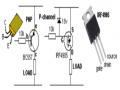
3. Transistor Amplifiers
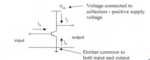
Transistor as an Amplifier
How do we use the transistor as an amplifier?
First, we must connect it appropriately to the supply voltages, input signal, and load, so it can be used.
A useful mode of operation is the common-emitter configuration
To make a practical circuit, we have to add bias and load resistors to ensure the transistor is at the desired operating point (operating in the right current range)
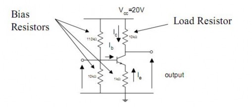
The resistors connected to the base ensure that the BE junction is forward biased. They effectively form a potential divider to reduce the voltage supplied to the base.
The emitter resistor work with the base resistors to stabilise the operating point wrt variations in b due to component variation and temperature by providing negative feedback.
Finally, the collector resistor provides the load.
4. Oscillators
es, radios, and metal detectors are among any devices that use oscillators.
A clock pendulum is a simple type of mechanical oscillator. The curate timepiece in the world, the atomic clock, keeps time according scillation within atoms. Electronic oscillators are used to generate sign
uters, wireless receivers and transmitters, and audio-frequency equip ularly music synthesizers. There are many types of electronic oscill hey all operate according to the same basic principle: an oscillator a
ys a sensitive amplifier whose output is fed back to the input in ph the signal regenerates and sustains itself. This is known as po ack. It is the same process that sometimes causes unwanted “howli
c-address systems.
An oscillator is a mechanical or electronic device that works on the principles of oscillation: a periodic fluctuation between two things based on changes in energy. Computers, clocks, watch
the m
most
ac to the
o als in
comp ment,
partic ators,
but t lways
emplo ase.
Thus, sitive
feedb ng” in
publi
The frequency at which an oscillator works is usually determined by a quartz crystal. When a direct current is applied to such a crystal, it vibrates at a frequency that depends on its thickness, and on the manner in which it is cut
from the original mineral rock. Some oscillators employ combinations of inductors, resistors, and/or capacitors to determine the frequency. However, the best stability (constancy of frequency) is obtained in oscillators that use quartz crystals.
In a computer, a specialized oscillator, called the clock, serves as a sort of pacemaker for the microprocessor. The clock frequency (or clock speed) is usually specified in megahertz (MHz), and is an important factor in determining the rate at which a computer can perform instructions.
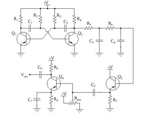
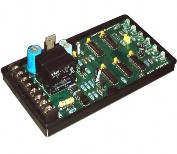
The circuit above shows:
Square wave oscillator: R1 through R4, C1 and C2, Q1 and Q2
First integrator stage: R5 and C3
Second integrator stage: R6 and C4
Buffer stage (current amplification): Q3 and R7
Final gain stage (voltage amplification): R8 and R9, Rpot, Q4, and C7
5. Converters
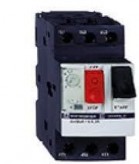
AC/DC three-phase converters with a full digital control. SieiDrive - SR32 devices are AC/DC three-phase converters with a full digital control, which are active in the four quadrants to supply constant voltage to the DC link of the AVy and AGy inverters. The SR32 converter is suitable to supply power to both single and multiple inverter systems connected to a common DC link.
Forward converter above:
Buck-derived transformer-isolated converter
Single-transistor and two-transistor versions
Maximum duty cycle is limited
Transformer is reset while transistor is off
A part of the regenerated power can be exchanged between the monitoring and regenerating drives; the exceeding power is regenerated back to the Mains via the SR32 converter. The output voltage of the SR32 converter is kept constant within a specified range even if the inverter operates in a regenerative mode untill it reaches the full current value supplied while functioning in a rectifier mode.
Part
Tot.
Description
Substit

Qty. | -utions | ||
R1, R4 | 2 | 2.2K 1/4W Resistor | |
R2, R3 | 2 | 4.7K 1/4W Resistor | |
R5 | 1 | 1K 1/4W Resistor | |
R6 | 1 | 1.5K 1/4W Resistor | |
R7 | 1 | 33K 1/4W Resistor | |
R8 | 1 | 10K 1/4W Resistor | |
C1,C2 | 2 | 0.1uF Ceramic Disc Capacitor | |
C3 | 1 | 470uF 25V Electrolytic Capcitor | |
D1 | 1 | 1N914 Diode | |
D2 | 1 | 1N4004 Diode | |
D3 | 1 | 12V 400mW Zener Diode | |
Q1, Q2, Q4 | 3 | BC547 NPN Transistor | |
Q3 | 1 | BD679 NPN Transistor | |
L1 | 1 | L1 is a custom inductor wound with about 80 turns of 0.5mm magnet wire around a toroidal | |
core with a 40mm outside diameter. | |||
MISC | Heatsink For Q3, Binding Posts (For Input/Output), Wire, Board |
Có thể bạn quan tâm!
-
 Tiếng Anh chuyên ngành Nghề Điện tử công nghiệp - CĐ Công nghiệp và Thương mại - 10
 -
 Tiếng Anh chuyên ngành Nghề Điện tử công nghiệp - CĐ Công nghiệp và Thương mại - 11
 -
 Tiếng Anh chuyên ngành Nghề Điện tử công nghiệp - CĐ Công nghiệp và Thương mại - 12
 -
 Tiếng Anh chuyên ngành Nghề Điện tử công nghiệp - CĐ Công nghiệp và Thương mại - 14
 -
 Tiếng Anh chuyên ngành Nghề Điện tử công nghiệp - CĐ Công nghiệp và Thương mại - 15
 -
 Tiếng Anh chuyên ngành Nghề Điện tử công nghiệp - CĐ Công nghiệp và Thương mại - 16
Xem toàn bộ 134 trang tài liệu này.
REFERENCE: Electric equipment
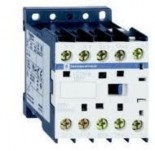
Heat pump Lightning arrester Magnetic starter
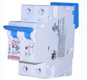
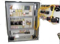
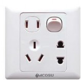
Circuit breaker Electrical system Sockets and switch
Microwave oven Oxygen generator Overload protector
Actuator Thermal relay Auto- starter