A MOSFET is a voltage controlled device and the current it will handle depends on its physical size and the way it is constructed. You cannot change this parameter.
For a load current up to about 35Amp, the gate current for a IRZ40 will be less than 0.25mA. When the gate voltage is 3v to 4v higher than the source, it turns on and the resistance between source and drain terminals is about 0.028 ohms. It will handle up to 35 amps.
The load determines the current through the MOSFET (not the MOSFET) and if it is less than 35 amps, a IRFZ40 is suitable for the application.
Comparison between a PNP transistor and P-channel MOSFET:
When the gate voltage is 4v LOWER than rail voltage, the MOSFET turns ON. The 10k resistor on the base of the transistor is needed to prevent the base current exceeding the amount of current needed by the transistor to deliver current to the load. However the 10k resistor on the gate of the MOSFET is not needed. Providing the voltage (up to 18v) on the gate rises and falls quickly, the MOSFET will not get hot. The critical period of time is the 0v to 3v section of the waveform as this is when the MOSFET is turning on.
Có thể bạn quan tâm!
-
 Tiếng Anh chuyên ngành Nghề Điện tử công nghiệp - CĐ Công nghiệp và Thương mại - 8
 -
 Tiếng Anh chuyên ngành Nghề Điện tử công nghiệp - CĐ Công nghiệp và Thương mại - 9
 -
 Tiếng Anh chuyên ngành Nghề Điện tử công nghiệp - CĐ Công nghiệp và Thương mại - 10
 -
 Tiếng Anh chuyên ngành Nghề Điện tử công nghiệp - CĐ Công nghiệp và Thương mại - 12
 -
 Tiếng Anh chuyên ngành Nghề Điện tử công nghiệp - CĐ Công nghiệp và Thương mại - 13
 -
 Tiếng Anh chuyên ngành Nghề Điện tử công nghiệp - CĐ Công nghiệp và Thương mại - 14
Xem toàn bộ 134 trang tài liệu này.
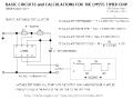
Charge Coupled MOSFET Relay
This circuit acts as an AC/DC relay with a rating up to 50 volts peak and up to 10 amps of current. The differential oscillator supplies voltage to the gates of the two FETs with good isolation will drawing only 1.5ma of current.
Charge coupled bi-directional power mosfet relay
The circuit below uses an inexpensive C-MOS inverter package and a few small capacitors to drive two power MOS transistors from a 12v to 15v supply. Since the coupling capacitor values used to drive the FETs are small, the leakage current from the power line into the control circuit is a tiny 4uA. Only about 1.5mA of DC is needed to turn on and off 400 watts of AC or DC power to a load.
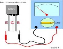
4. Transistors
A transistor is a semiconductor device used to amplify and switch electronic signals. It is composed of a semiconductor material with at least three terminals for connection to an external circuit. A voltage or current applied to one pair of the transistor's terminals changes the current flowing through another pair of terminals. Because the controlled (output) power can be much more than the controlling (input) power, a transistor can amplify a signal.
The transistor is the fundamental building block of modern electronic devices, and is ubiquitous in modern electronic systems. Following its release in the early 1950s the transistor revolutionized the field of electronics, and paved the way for smaller and cheaper radios, calculators, and computers, among other things.
5. Resistor
Physically resistance is a measure of a material’s opposition to charge flow or current.
Resistance is measured in units called Ohms
The higher the resistance of a material, the more potential difference is required to maintain a current.
Under ordinary temperatures, perfect conductors do not exist. All substances including copper and other metals, offer a definite amount of resistance to the flow of current. The metal resistance offered depends upon four distinct factors:
1. The nature of the material as the conductor
2. The temperature
3. The length of the conductor
4. The cross sectional area of the conductor.
It is sufficient to know that the resistance of a metallic conductor will rise if its temperature is raised, its length is increased, its thickness is decreased, and vice versa.
84
6. Capacitor
A capacitor (formerly known as condenser) is a device for storing electric charge. The forms of practical capacitors vary widely, but all contain at least two conductors separated by a non-conductor. Capacitors used as parts of electrical systems, for example, consist of metal foils separated by a layer of insulating film.
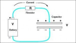
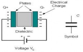
A capacitor is a passive electronic component consisting of a pair of conductors separated by a dielectric (insulator). When there is a potential difference (voltage) across the conductors, a static electric field develops across the dielectric, causing positive charge to collect on one plate and negative charge on the other plate. Energy is stored in the electrostatic field. An ideal capacitor is characterized by a single constant value, capacitance, measured in farads. This is the ratio of the electric charge on each conductor to the potential difference between them.
Capacitors are widely used in electronic circuits for blocking direct current while allowing alternating current to pass, in filter networks, for smoothing the output of power supplies, in the resonant circuits that tune radios to particular frequencies and for many other purposes.
The capacitance is greatest when there is a narrow separation between large areas of conductor, hence capacitor conductors are often called "plates," referring to an early means of construction. In practice the dielectric between the plates passes a small amount of leakage current and also has an electric field strength limit, resulting in a breakdown voltage, while the conductors and leads introduce an undesired inductance and resistance.
7. Component values
Electronic components have various ways of denoting the values; increasingly (due to advances in printing technology) they have numbers printed on.
Decimal points are often denoted by placing the multiplier in as a decimal point,
e.g. resistors labelled 5R6 = 5.6ohms; 4k7= 4.7kohms, and capacitors labelled 2u2 (or 2µ2) = 2.2 microfarads.
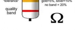
Resistor Colour Codes
Resistors are often labelled using colour bands; the first three of these denote the value, and a fourth may show the tolerance. The following code is used for the values:
The first digit is the one nearest the end.
The two digits are the value; the multiplier adds zeros.
Examples:
red + red + orange = 22 followed by 3 zeros, = 22000 ohms = 22kOhms
yellow + purple + green = 47 followed by 5 zeros = 4,700,000 = 4.7 mgO
grey + red + black = 82 followed by 0 zeros, = 82 ohms
Small resistors (< 10ohms) may need extra colours for the multiplier:
Gold: multiply by 0.1 Silver: multiply by 0.01
High accuracy resistors sometimes use an extra band for an extra digit; then the five bands are digit 1, digit 2, digit 3, multiplier, tolerance.
Resistor Tolerance (accuracy) Code
A tolerance of 10% means that the component value may be anything between the nominal value -10% and the nominal value +10%, so a 10% tolerance 12k resistor may have a value between (12-1.2) and (12+1.2), or 10.8k
- 13.2k.
Capacitor Values
Capacitors have various methods for marking the value: Value written “normally” - e.g. 2.2µF = 2.2 microFarads
- Written using the prefix as the decimal point - e.g. 2u2 = 2.2 microFarads
- Using a three digit code: two digits are value, and then the number of zeros, with the value in picoFarads: e.g. 334 = 330000 pF = 330nanoFarads.
- Using a three-band colour code similar to the resistor code, to give the value in picoFarads.
- Extra numbers or bands may indicate the maximum working voltage.
IV. EXERCISE
Mục tiêu: Kiểm tra kết quả đạt được của người học về sự hiểu biết các từ vựng chuyên môn cũng như ngữ pháp, kiến thức và kỹ năng đọc hiểu đã được học để hoàn thành các bài tập ứng dụng cũng như áp dụng vào trong môi trường làm thực tế sau khi tốt nghiệp.
1. Complete the sentences
voltage valve reverse-biased difference direction forward-biased polarity diode
a. A diode is an electrical component acting as a one-way ………… for current.
b. When ………….. is applied across a diode in such a way that the diode allows current, the diode is said to be ……………..
c. When voltage is applied across a ………….. in such a way that the diode prohibits current, the diode is said to be …………………….
d. A check valve allows fluid flow through it in only one ……………..
e. The essential …………………….. between forward-bias and reverse-bias is the ………………….of the voltage dropped across the diode.
2. Answer the following questions
a. What is the forward voltage called ?
.............................................................................................................................
.............................................................................................................................
b. What must be used to sunstain the current going through the diode?
.............................................................................................................................
.............................................................................................................................
c. What is the Peak Inverse Voltage ?
.............................................................................................................................
d. What is the purpose of the gate in the thyristor?
.............................................................................................................................
.............................................................................................................................
e. What can you do to turn the thyristor off?
.................................................................................................................................
.................................................................................................................................
3. Decide True or False
a. The thyristor´s ability is to switch very large currents at very high (hundreds of volts) voltages.
b. The MOSFET determines the current through itself.
c. A MOSFET is a voltage controlled device.
d. A transistor is composed of a semiconductor material with at least three terminals for connection to an external circuit.
e. A thyristor is a semiconductor device used to amplify and switch electronic signals.
4. Listen and Check
conduction voltage base feedback
quickly biased transistor pulse gate
When the ………… is made positive with respect to K by the application of a gating………. , Tr2 will turn on and its collector voltage will fall rapidly. This will cause the pnp ……………… Tr1 base emitter junction to become forward
………., turning on Tr1. A large current will now be flowing between A and K. The action described happens very …………… as the switching on of Tr2 by Tr1 is a form of positive …………. with each transistor collector supplying large current changes to the ……….. of the other. As Tr1 collector is connected to Tr2 base, the action of switching on Tr1 connects Tr2 base virtually to the high positive ……………. at A. This ensures that Tr2 ( and therefore Tr1) remains in…………, even when the gating pulse is removed.
5. Match the ideas
1. When the gate voltage is 4v LOWER a. the MOSFET will not get hot