placed on a closet door, for example, can be used to control the light in a closet.
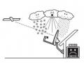
Typical central control lighting system design. The controller handles on/off/dim functions of all attached branch lighting circuits based on user input from keypads, switches, and remote controls.
![]()
Distributed Control System
Distributed lighting control systems invariably use PLC (Power Line Carrier) technology such as X10 to control light loads. There are a wide range of PLC controllers and modules available to handle almost any lighting (and appliance) load in the home. For more details on PLC signaling technology and X10 modules. Modules and controllers make up most of the system components.
Có thể bạn quan tâm!
-
 Tiếng Anh chuyên ngành Nghề Điện tử công nghiệp - CĐ Công nghiệp và Thương mại - 4
 -
 Tiếng Anh chuyên ngành Nghề Điện tử công nghiệp - CĐ Công nghiệp và Thương mại - 5
 -
 Tiếng Anh chuyên ngành Nghề Điện tử công nghiệp - CĐ Công nghiệp và Thương mại - 6
 -
 Tiếng Anh chuyên ngành Nghề Điện tử công nghiệp - CĐ Công nghiệp và Thương mại - 8
 -
 Tiếng Anh chuyên ngành Nghề Điện tử công nghiệp - CĐ Công nghiệp và Thương mại - 9
 -
 Tiếng Anh chuyên ngành Nghề Điện tử công nghiệp - CĐ Công nghiệp và Thương mại - 10
Xem toàn bộ 134 trang tài liệu này.
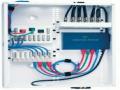
Typical distributed control lighting system design. The system uses PLC technology to perform on/off/dim functions in X10 light switches and outlets. Control can be from anywhere in the electrical system wiring.
Switchable outlets can replace traditional wall outlets to control plug-in lights. Dimmable and switchable only plug-in modules can be used in existing wall outlets to control lamps or other existing light fixtures with a cord.
Several different types of controllers are available. Programmable controllers can be used to configure scenes based on events such as the time of day. Keypad-like wall switches can control several individual X10 devices.
Zones consisting of several fixtures can be established by combining switching modules into a group by assigning them the same house and unit code. Modules with the same house/unit code will operate identically.
Scenes can be programmed into several wall mount touchscreens or using a PC interfaced to the power line and running lighting automation software. Several wall switches are capable of “learning” scene setting and recalling the scene upon receiving a specific X10 code.
IR and RF remote control devices are also available to control individual modules or groups of modules assigned the same code.
Since PLC distributed control lighting system components rely on the power line as a network, they are subject to potential problems with power line communications and some skill (and network conditioning hardware) may be required to achieve a reliable system, but they have several advantages over central control systems. They are retrofitable. Most X10 lighting modules are either plugged into an existing outlet, or replace traditional light switches. Other components can be connected to existing electrical wiring.
They use traditional electrical wiring. They do not require any special house wiring techniques or additional control signal wiring. Extra electrical wiring may be needed in a location where a controller is mounted, typically at eye level on a wall surface.
![]()
Interface with Home Automation Systems
Both types of lighting systems can be interfaced to a whole house automation system or to a PC for more elaborate control. Central control systems typically have an EIA-232 (often referred to by its older designation of RS-232) serial computer interface. The software used to perform the interface is proprietary to each manufacture. The distributed control PLC system can be easily controlled by any device with an X10 PLC interface. There are several PC to X10 power line interface devices available with PC software included.
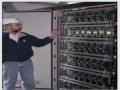
Central Control Panel
The central controller is usually contained in a large panel mounted near the main electrical load center of the home and contains a microcontroller for all system operation. The microcontroller is programmed during installation to assign keypad switches to lights and/or lighting scenes, create lighting zones and scenes, and assign contact closure inputs to lights or scenes. It also contains the remote controlled lighting zone switches, both on/off only and dimmable to handle the hardwired lighting circuits. It is wired similarly to an electrical panel since electrical wiring from lighting circuits is brought to the lighting panel and connected to an internal switch circuit.

Components of a central control system all connect to the central control panel through electrical wiring or dedicated control wiring.
*Lighting installation
The Basic Lighting Circuit Diagram
Circuit protective conductor omitted for clarity - the bare earth wire in “twin & earth” although not shown in the circuit diagram, each point should be provided with a means of earthing-
- from live, fuse, then to a switch, and then to the light and then to neutral. On a full installation, it is necessary to have more than one light on a circuit, and bearing in mind that the common wiring method is to use a cable with 2 conductors, the best way to wire a
lighting circuit is as follows :- L live • N
neutral • Ls Live, switched.
The twin cable to the switch is shown with both cores red. When stripping back the sheathing, care must be taken to ensure that the sheathing for the cable outside the enclosure is continuous into the enclosure. Many light fittings (mối nối) do not have a neat arrangement of connector blocks (hộp nối). When changing a “proper” light fitting for a more elaborate type, you must use a proper junction box to accommodate the supply & switch cables, and run a separate twin cable through the hole in the ceiling into the new light fitting.
Installing Additional (1-way) Light Points
If the supply is being taken from the consumer unit, then it will be from a fused way.
Adding a new light fitting - controlled by same switch
In the wiring diagram above, the light only needs a switched live & a neutral. To connect another light, simply double up to these terminals. The new light will be ON and OFF just as the one you connected to. If the light has to be controlled by another switch, then check the next section.
Adding a new light fitting with its own switch
Another light controlled by its own switch will be wired as shown in the basic wiring diagram above to get a supply for the new light:
connect into the L & N terminal in an existing light & run a cable to the new light fitting position and wire it up as shown in the basic wiring diagram
break into the lighting supply cable - be sure to identify the correct cable
add a fused (5A) connection unit to a suitable source.
2-way Lighting Circuit Diagram
![]() 2-way means two ways to
2-way means two ways to
3-way Lighting Circuit Diagram
switch the light on or off - think about a landing light. That can be switched on or off at both the switch on the landing and at the switch at the bottom of the stairs.
In this diagram, the light is OFF, power goes to the 1st switch and along the upper strapper (thanh dẫn trên) to the 2nd switch. If the 1st switch is operated, power will get to the 2nd switch along the lower strapper (thanh dẫn dưới) If either of the switches is operated, the light will be ON, and then if either switch is operated the light will be OFF.
Reconsider 2 way lighting - see how throwing either of the two switches in any state causes the strappers to swap ON & OFF - and this affect the light. So if the strappers were crossed at any point between the two switches, the light would change so . If a changeover switch is introduced into the circuit, it would give the desired effect, independently of the other 2 switches intermediate switch changeover crossover.
Lighting circuit
Every electrician has his or own way of wiring lighting circuits but basically there are only three different ways, two of these are almost identical.
Method 1:
This is what I consider the hard way, It is difficult because you do not have lots of room inside the switch box but has the advantage of having a neutral wire inside which could be useful for wall lights etc!
Here is a diagram of the connections at the switch with the earth removed.
As you can see from the above diagram the 3 Neutral wires are all connected together in a insulated terminal, the live in and out are connected together at the non switched side of the circuit and the switched live goes to the Lamp!
Method 2: Loop in wiring system
The above diagram shows how the power is fed from the consumer unit to the first light and then to each consecutive light on the circuit hence it is named the circuit wire. The earth wires are not shown for clarity. Try and follow the path of the electricity.