14, He waited in the rain for an hour.
15. During my teen years, I grew tall.
b. Make six sentences with the six sentence pattern above
1. Subject + Verb
...........................................................................................................................
2. Subject + Verb + Object
...........................................................................................................................
3. Subject + Verb + Complement
...........................................................................................................................
Có thể bạn quan tâm!
-

 Tiếng Anh chuyên ngành Nghề Điện tử công nghiệp - CĐ Công nghiệp và Thương mại - 2
 -
 Tiếng Anh chuyên ngành Nghề Điện tử công nghiệp - CĐ Công nghiệp và Thương mại - 3
 -
 Tiếng Anh chuyên ngành Nghề Điện tử công nghiệp - CĐ Công nghiệp và Thương mại - 4
 -
 Tiếng Anh chuyên ngành Nghề Điện tử công nghiệp - CĐ Công nghiệp và Thương mại - 6
 -
 Tiếng Anh chuyên ngành Nghề Điện tử công nghiệp - CĐ Công nghiệp và Thương mại - 7
 -
 Tiếng Anh chuyên ngành Nghề Điện tử công nghiệp - CĐ Công nghiệp và Thương mại - 8
Xem toàn bộ 134 trang tài liệu này.
4. Subject + Verb + Indirect Object + Direct Object
...........................................................................................................................
5. Subject + Verb + Object + Complement
...........................................................................................................................
6. Subject + Verb+ Adver
...........................................................................................................................
III. CONTENT
Mục tiêu: Hình thành kiến thức và kỹ đọc hiểu cho người học để người học có thể đọc được một số tài liệu liên quan đến lắp đặt và kiểm tra bảng điện áp bằng tiếng Anh.
Passage 1: Install and check low voltage panel

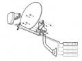
Installing a media network panel with modules for phone, data, and video lines provides flexibility and the assurance that you have reliable connections.
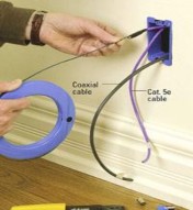
Step 1
Cut openings and install a low-voltage box at each outlet location. Between two studs, cut an opening for the network panel. Run Category 5e cable for phone and data lines and coaxial cable for broadband or satellite lines. This is the hardest and most time-consuming part of the job.
Step 2
Label each end of the cables as you pull them. Leave 12-18 inches of excess cable at each opening. Run a 14/2 electrical cable from the breaker panel to the network box opening. Remove knockouts and fit the box with bushings to protect the cables. Feed the cables into the box and fasten them to the studs.
Step 3
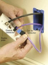
Purchase Category 5e connectors, selecting colors to indicate use (blue for data lines and white for phone lines for example). Strip about 21/2 inches of cable jacket and straighten the wires. Using the A color key on the eight-conductor connector, push the wires into their color-coded slots. Press them into place using the punch tool provided.
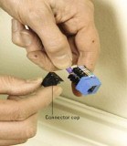
Step 4
Check to make sure the wires are positioned correctly, and then trim any excess wire with a diagonal cutter. Push the connector cap into place. Fit the coaxial cable with type-F connectors.
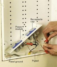
Step 5
Remove knockouts and fasten the surge protector and GFCI power module into the network box. Strip the 14/2 cable and connect the module following the manufacturer's instructions. Fasten the module into place using screws provided. Leave caps in place to guard against debris falling into the receptacles.
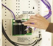
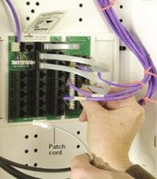
Step 6
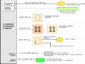
Snap a telephone distribution panel into place. It routes incoming telephone lines. Attach a voice and data module (or more if you need them -- each module serves six wall outlets). Wire each household extension line to this module. Connect patch cords between these modules and the appropriate plug-in.
Step 7
For each incoming line strip about 21/2 inches of cable jacket from the Category 5e cable. Following the manufacturer's instructions straighten and fan the wires and place them into the color-coded brackets adjacent to the appropriate module. Press them into the brackets with a punch tool and snip off the excess.
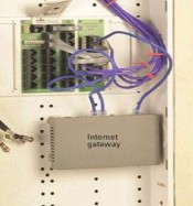
Step 8
Snap the Internet gateway into place. Connect the incoming modem line to the WAN (wide-area network) port with Category 5e-rated patch cords. Connect computer lines to the gateway. Configure the gateway using the software provided on a CD packaged with the Internet gateway.
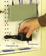
Step 9
Install a new breaker to power the dedicated 15-amp lines. Test for power. Remove a protective cap from one of the GFCI receptacles and plug in the Internet gateway transformer.
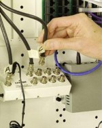
Step 10
Attach type-F coaxial connectors to each incoming coaxial line, using coaxial stripping and crimping tools. Attach the incoming service cable to the CATV/ANT connection. Attach the other lines according to their labels. Plug the module transformer into the power module.
Step 11
Snap the connectors into the duplex plate. (You can choose from plates that have from two to six openings.) Test each line. Gently feed the cables into the wall and attach the plate to the outlet box.
Testing the system:
At the network panel find the cable being tested and touch the tester to it. If the line is correct, the tester emits a high-pitched sound. If there is no sound, check other lines until you find the connected line. Adjust the connection at the panel to correct any mistakes.
Passage 2: : Install and check medium voltage panel
Fig. 2: Cable switch panel CS (shown with main bus in the middle)
1. Sockets for capacitive voltage detection system
2. Manual operation for the mechanism of the load-break
/disconnecting function
3. Indicator “Fuse intact / Fuse blown”
4. Switch position indicator for load- break and for grounding function “CLOSED-OPEN-GROUNDED”
5. Manual operation for the mechanism of the grounding function
6. Sockets for capacitive voltage detection system
7. Insulating cap on bus bar (for >
Fig. 3: Fuse switch panel FS (shown with main bus on top)
14. Cable compartment cover/ door
15. Gas-insulated vessel for switching device
16. Bushing-type insulator for feeder
17. Cable connection
18. Cable termination (not in scope of supply)
19. Cable connection compartment
20. Three-position switch
21. Grounding bus bar
22. Spring-operated mechanism for three- position switch
23. Grounding connection (for location see dimension drawings)
24. Option: Local-remote switch for the
15 kV)
8. Bus bar
9. Bushing-type insulator for bus bar
10. “Ready-for-service” indicator for switching device
11. Interlocking lever of cable compartment cover (with three- position switch)
12. Pressure relief device for switching device
13. Locking device for three- position switch
motor operating mechanism of the three- position switch
25. Option: Momentary-contact rotary control switch “CLOSED – OPEN” for motor operating mechanism for three- position switch
26. Option: HV HRC (current limiting) fuse
27. Post insulator
28. Low voltage compartment
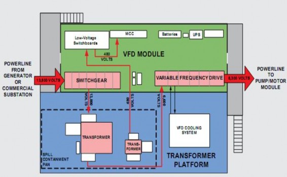
Three VFD modules will be installed at Pump Stations 1, 3, 4, and 9. All three will contain VFDs, while two will also contain switchgear. A platform adjacent to the module will hold a cooling system for the liquid-cooled VFD, a transformer to step down the incoming power from 13,800 volts to 6,600 volts, and a station transformer to provide 480-volt power to the module. The VFD controls the frequency of the power in order to vary the speed of the pump motors. The photo below shows a 3-D rendering of the three VFD modules planned for Pump Station 4.
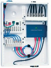
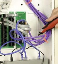
The photo above shows part of the ABB switchgear with the front panels open. The switchgear consists of a series of sections. The frst on the left houses the control wiring for the switchgear. The section at right contains the circuit breaker and the computer (multifunction protective relay) that controls that breaker. Each VFD module will have six or seven breakers. The computer can sense the full range of current and can be programmed from a laptop computer. In addition, a communications module will interface with the PLC.
Switchgear
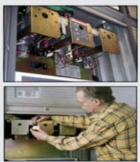
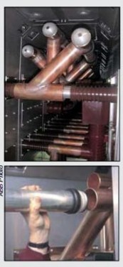
The actual switching mechanism is contained in the back of the unit so that operators are never exposed to the medium-voltage components. Copper tubes (or bus) that supply the power to the circuit breakers are shown at left. The photos above show the breaker mechanism and how an operator can lock the breaker.
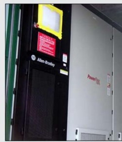
The variable frequency drives (VFD) are manufactured by Allen- Bradley, and each consists of six sections. The section above at left houses the power cable terminations in the back and the controls in the front, while the next section contains the power electronics that condition the power. The other sections house capacitors, the DC link, and the pumps for the liquid cooling system. A single VFD module produces the frequency- controlled power needed to run a single mainline pump motor.