* n : coefficient of heat release of boiling water in the tube at t = 7 0 C [3].
n = A 0 q 0.7 kcal/m 2 hK
Water boils at 7 0 C, so look up the graph of Figure 2-2a [3], we get A 0 = 9.3 So put in, we have:
n = 9.3 q 0.7 kcal/m 2 hK = 10.8 q 0.7 W/m 2 K
Because the tube is thin, it is approximate to see the temperature of 02 wall surfaces
tubes are equal and equal to t W
We have: q = t (t f – t W ) = n (t W – t s )
Derived from:
n=_
t f - t W
= tt _
t t W -t s t n _ _
Steps for iterative calculation to find n :
Select:
n=_
t_
tt_
tn_
= 5.87. It follows that t n =
tt_
5.87
= 11.5 - t n .
5.87
Deduce t n = 1.67 0 C Substitute, we have:
n = 10.8 q 0.7 = 10.8 ( n t n ) 0.7 = 10.8 ( n 1.67 ) 0.7
Infer: n = 6.544.4 W/m 2 K
Review:
n=_
t_
6544.4 = 5.95.
1100
Error from assumption 1.34% < 5%: satisfied
* Heat transfer coefficient k.
k = 1
n_
first
1___
t_
= 1
6544.4
first
0.0012__
15.6
first
1100
= 878.2 W/m 2 K
+ Cooling capacity:
Q 0 = kF t = 878.2 x 0.033 x (18.5 – 7) = 333 W
Water cooling time:
=Ql=111,200_
= 334 s 6 minutes
Q 0 333
3.3.2. Amount of charging medium
a. Amount of water loaded
According to formula (2.2), the amount of water to be loaded is:
G n = 1.2
Q 0
r ( t 0 )
, kg
In there:
r(t 0 ): latent heat of vaporization of water at evaporation temperature t 0 We have: t 0 = t f – 5 = 12 – 5 = 7 0 C
Look up the table “Water and steam on the heat saturation line
degrees", we get:
r(7 0 C) = 2.484 kJ/kg
So the amount of water to be loaded is: G n = 1.2 x 111.2 / 2.484 = 0.537
kg
b. Determine the amount of Zeolite loaded
Based on the evaporation pressure of water and the graph of adsorption curve
Zeolite isotherm with respect to water [8], showing the state that the zeolite has sufficiently adsorbed water:
Temperature of the refrigerant pair: t a2 = t W + 5 = 25 + 5 = 30 0 C = 86 0 F,
with tW : cooling water temperature 25 0 C.
Evaporation pressure of water: t 0 = 7 0 C p 0 = 0.010142 bar = 7.6mmHg
From the graph deduce the concentration of water/Zeolite (kg/kg) = 0.24
So the amount of Zeolite loaded is: G Z = G n /0.24 = 0.517/0.24 = 2.154 kg
3.3.3. Steam generator - absorber
a. Request
+ Filling water volume: V n = 0.54 liters = 0.54.10 -3 m 3
+ Volume of Zeolite loaded: V Z = G Z / Z = 2.154/650 = 3,31.10 -3 m 3 In which:
Z = 650 kg/m 3 : density of Zeolite
+ Volume of refrigerant in the device: V c = V n + V Z = 3.85.10 -3 m 3
b. Device structure
+ Choose 06 absorber tubes 0.8m long, stainless steel tubular type: outer tube 60x1.2mm; The inner tube is 27x1.2mm drilled with holes, the outside is covered with 1mm thick stainless steel mesh.
+ Total volume of refrigerant:
V = [3.14 (0.0576 2 – 0.029 2 )/4] x 0.8 x 6 = 9.3.10 -3 m 3 : guaranteed
c. Total amount of heat required
* Amount of heating for equipment and Zeolite:
Q gn1 = (M TB C TB + M Z C Z )(T g2 – T a2 ) , kJ
In there:
M TB : weight of equipment, weighing 32kg; C TB = 0.5 kJ/kgC: specific heat capacity of stainless steel M Z = 2.154 kg: mass of Zeolite
C Z = 0.06 kJ/kgC: specific heat of Zeolite t g2 = t gn2 – 5 = 88 – 5 = 83 0 C;
Select the temperature of hot water heating to 90 0 C out 88 0 C: t a2 = t W + 5 = 25 + 5 = 30 0 C
Infer: Q gn1 = (32 x 0.5 + 2.154 x 0.06)(83 – 30) = 854.8 kJ
* Amount of heat for heating and vaporizing refrigerant water:
Q gn2 = M n [C n (T g1 – T a2 ) + r g ] , kJ
Where: M n = 0.537 kg: mass of water;
C n = 4.174 kJ/kgC: specific heat capacity of water at an average temperature of 50 0 C
t g1 = 70 0 C: temperature at which steam begins to separate from Zeolite
r g = 2,333 kJ/kgC: latent heat of vaporization of water at 70 0 C Inferred: Q gn2 = 0.537 [4,174 (70 – 30) + 2.333] = 1.342.5 kJ
* Total heat supplied to the steam generator:
Taking into account heat loss to the environment and storage (see about 20%), the total amount of heat supplied to the steam generator is:
Q H = 1,2 (Q gn1 + Q gn2 ) = 1.2 x (854.8 + 1,342.5) = 2,637 kJ
d. Heating time for steam generator
Heat exchanger area:
Volume of water 0.537 liters = 0.537.10 -3 m 3 The volume of the device's refrigerant pair:
(0.0576 2 – 0.027 2 ) x 3.14 /4 x 0.8 x 6 = 9,754.10 -3 m 3
Occupancy rate: 0.537 / 9,754 = 5.5% So heat transfer area:
F = 0.055 x 0.06 x 3.14 x 0.8 x 6 = 0.05 m 2
+ Heat transfer coefficient of steam generator:
The heat transfer coefficient k is calculated as follows:
k = 1
n_
first
1___
t_
Where: - = 1.2mm : thickness of inner tube
- = 15.6 W/mK: coefficient of thermal conductivity of stainless steel.
* n : heat dissipation coefficient of forced flowing water crossing parallel pipes [2]
Parameters of hot water at 88 0 C [4]:
= 0.309.10 -6 m/s 2 ; = 0.681 W/mK; Pr = 1.84.
Select flow rate: = 0.4 m/s Sieve-non-standard:
Re = . d
= 0.4.0.06 = 19.418, Π[ 10 3 10 5 ]
0.309.10 - 6
Nut-xen standard: Nu = 0.26 Re 0.65 Pr 0.33 (
Pr ) 0.25 _
Pr W
Approximate, choose surface temperature t W = t s + 3 = 70 + 3 = 73 0 C
Pr W = 2.45 Effect factor for rows of pipes (06 rows):
So, we have:
= 0.60.9 1x4 = 0.917 _ _
6
Nu = 0.26 x 19,418 0.65 x 1.84 0.33 x ( 1.84
2.45
) 0.25 x 0.917 = 181.4
Calculate the heat transfer coefficient:
Nu ._ _ 181.4.0.681_ _
= 2.059 W/m 2 K
n l 0.06
* t : coefficient of heat release of boiling water in the tube
Approximate, taken as the coefficient of heat release of boiling water in the tube at
chiller and equal to 6.544.4 W/m 2 K
* Heat transfer coefficient k.
k = 1
n_
first
1___
t_
= 1
2059
first
0.0012__
15.6
first
6544.4
= 1.397.8 W/m 2 K
Heating capacity:
Q gn = kF t = 1.397.8 x 0.05 x [(90 + 88) - (70 + 83)] / 2 = 524 W
Heating time:
=QH_
Q gn
= 2,637,000
524
= 5.032 s 1g24 min
3.3.4. Condensers
a. Select device model
b. Power equipment
Q K = G n . r (70 0 C) = 0.537 x 2,333 = 1.252.8 kJ
Condensing time of condenser must be less than steam generation time in steam generator. Reserve, taken as 0.8: 0.8 x 5.032
= 4.026 s
Capacity of condenser:
Q K = 1.252,800
4.026
= 311.2 W
c. Condenser design calculation
+ Condensing temperature:
t K = t kk + 10 = 37.8 + 10 = 48 0 C
With t K = 37.8 0 C: average summer air temperature in Quang Ngai
Heat transfer coefficient of condenser:
k = 1
n_
first
1___
t_
In there:
A/ n = 23.3 W/m 2 K: heat dissipation coefficient of the wind [7].
B/ = 0.0008m: thickness of stainless steel pipe, very thin, so / 0 C/ t : heat dissipation coefficient of condensate, >> n , so 1/ t 0 So, approximate heat transfer coefficient K n = 23.3 W/m 2 K.
Heat transfer area of condenser:
F = Q CZK
k t _
311.2
= 23.3(70 - 37.8)
= 0.415 m 2
+ Total length of heat exchanger tubes:
L = F
dtb_
0.415
= 3.14(16 - 0.8)10- 3
= 8.7 m
3.3.5. Hot water heater
For simplicity, the experimental model chooses a resistive hot water heater with an electrical capacity of 1,000W .
3.3.6. High pressure tank
V B = V n / 0.8 = 0.54.10 -3 / 0.8 = 0.68.10 -3 m 3
Choose a vase that is a horizontal stainless steel tube ( 90x300x1,2). Actual volume of the tank: 1.8.10 -3 m 3 : guaranteed
3.4. MODEL MANUFACTURING
3.4.1. Manufacturing method
a. Manufacturing process of the absorber tube of the steam-steam generator
extra
b. Fabrication of condenser
c. Build evaporator
3.4.2. The process of vacuuming and filling water is as follows:
3.4.3. Measuring devices
3.5. MEASURE, EXPERIENCE ON MODELS
3.5.1. Experiment 1 : Determine the change of refrigerant water temperature over time
Experimental results of the model in Quang Ngai on June 9, 2012. Cold start (open throttle at 14 o'clock):
- Outdoor air temperature 30 0 C
- Heating water temperature 90 0 C
Experimental parameters to measure the water temperature to be cooled tn are summarized in the following table:
Table 3.1. Cooling water temperature according to experimental time.
Time (g) | 14:00 | 2:02 pm | 14:04 | 14:06 | 14:08 |
t n ( 0 C) | 25.4 | 24.8 | 22.4 | 20.3 | 18 |
Time (g) | 14:10 | 14:12 | 14:14 | 14h16 | 14:18 |
t n ( 0 C) | 15.8 | 15.1 | 14.1 | 13.3 | 12.6 |
Time (g) | 2:20pm | 14:22 | 2:24 pm |
|
|
t n ( 0 C) | 12.1 | twelfth | twelfth |
|
|
Maybe you are interested!
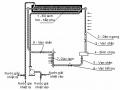
Figure 3.13. Graph of cooled water temperature over time
3.5.2. Comment
In the first 10 minutes, the water temperature drops very quickly, almost linearly (except for the first minute); the water temperature is more than 15 0 C. For the next 10 minutes, the temperature drops more slowly, the water temperature is more than 12 0 C. And for the rest of the minutes, the temperature remains constant at 12 0 C.
Figure 3.14. Graph of cooling time by heating water temperature
3.5.4. Comment
As the heating water temperature increases, the cooling time decreases.
3.6. PRICE OF MODEL
CONCLUSIONS AND RECOMMENDATIONS
1. CONCLUSION
1.1. The research contents have been achieved:
- Surveying and analyzing waste heat energy sources to
chilled.
- Synthesize the theory of adsorption refrigerant pair, especially water/zeolite refrigerant pair.
- Synthesize the theory of adsorption chillers, especially intermittent adsorption chillers without pumps.
- Building, calculating and designing water/zeolite adsorption air conditioners using intermittent exhaust heat energy in accordance with Vietnamese conditions.
- Calculation, design, manufacturing model of water absorption air conditioner/zeolite to cool water using hot water.
- Experiment on the device model. Result of water cooling
reached 12 0 C after 18 minutes of cooling.
1.2. Exists:
- Due to limited manufacturing technology and limited budget, the refrigeration system has not been able to ensure the tightness, and cannot be equipped with an automatic vacuum device for the system. Therefore, the vacuum of the system cannot be kept for a long time, so before we want to operate this air conditioner, we must conduct a vacuum to ensure the cooling capacity.
- Due to the limited time, the study has not investigated the influencing factors and found measures to improve the efficiency of the adsorption air conditioner model.
2. RECOMMENDATIONS
2.1. Areas where research results should be used:
The successful manufacture of this adsorption chiller shows that this topic has great potential to be perfected, developed and put into commercial production.
Areas where the results of the project can be used well:
- High-end resorts: Currently, in 5-star hotels and resorts, people are forced to use resistive absorption refrigerators and some places use resistive absorption air conditioners to ensure quietness. for VIP visitors. These machines are very expensive right now, so the adsorption chillers as a result of the boiler flue gas project will certainly compete.
- Aquatic plants: Currently, the demand for cold water (15 .)
18) 0 C for seafood processing by seafood factories is very large and consumes a considerable amount of electricity. These factories have a large amount of waste smoke from the boiler, so the application of adsorption air conditioners using exhaust gas energy is very high.
In addition, there are a number of other consumers such as supermarkets, ....
2.2. Future research directions:
- Continue to complete the survey of influencing factors and find measures to improve the efficiency of the adsorption air conditioner model.
- Study on model of adsorption air conditioner using large capacity exhaust heat energy with pump to apply to large consumers.