c. Additional conventions for welding symbols are indicated in the following table:
Sub-symbol
Meaning of sub-symbols | Sub-symbol position | ||
Main side | Side | ||
The convex part of the weld is cut to be flush with the base metal surface. |
| ||
| The weld is machined to have an even transition from the weld metal to the base metal. |
|
|
Welds are made during assembly. |
| ||
Discontinuous welds distributed in a chain pattern |
|
| |
| Discontinuous welds or staggered weld points | ||
| The weld is made according to the closed circumferential diameter of the symbol. d = 3 ÷ 4 mm | ||
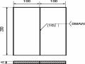
The weld is made along the open circumferential line. This symbol is for visible welds only. Size of the specified symbol: Height from 3 ÷ 5 mm Length from 6 ÷ 10 mm | |||


Maybe you are interested!
-
 Basic manual arc welding Welding Profession - Lao Cai College - 19
 -
 Practice Exercise 2: Welding “T” Corner Without Chamfer 2 Carbon Steel Plates Using Gmaw Welding Method At 3F Position (S=10Mm)
 -
 T-Bevel Welding Technique Without Bevel Position:
 -
 Low Carbon Steel Welding Rod Symbol According to Japanese Standards (Jis).
 -
 Low Carbon Steel Contact Welding Mode (Single Phase AC)
d. The welding symbol convention for the main side is written above (Figure 15.1.6a) and for the secondary side is written below (Figure 15.1.6b). The dash of the weld line indicates the welding position.

Figure 15.1.6 Convention on the side of the weld symbol
e. The smoothness of the machined surface of the weld can be indicated above or below the horizontal line of the weld position line and placed after the weld symbol (Figure 15.1.7) or can also be indicated in the technical conditions on the drawing without the need for a symbol.

Figure 15.1.7 Convention for recording the smoothness of machined surface of welds
f. If the weld has a check mark, this symbol is written below the welding position line (Figure 15.1.8).

Figure 15.1.8 Convention for marking weld inspection symbols
g. If the drawing contains similar welds, it is only necessary to record their quantity and identification number. This symbol can be recorded above the horizontal line of the welding position line (if the weld symbol is recorded above the horizontal line of this line) (Figure 15.1.9)

Figure 15.1.9 Convention for notating similar welds
h. Welding materials (welding rods, welding wire, welding flux, coating flux...) may be specified in the technical conditions on the drawing or may not need to be specified.
i. Currently, there are many different welding methods and welding types, but we have defined some conventions for notating welding methods and basic types as well as the most commonly used welding joint types as follows:
T - Manual arc welding.
A - Automatic welding under flux without using flux pads or pre-welding.
D1 – Automatic welding under flux using steel backing plate.
1 - Automatic welding under flux using copper-flux backing plate. 2 - Automatic welding under flux using flux pad.
DH - Automatic welding under flux with pre-tacking. Đbv - Automatic welding in protective gas environment.
B – Semi-automatic welding under flux without backing, flux pads or pre-welding.
Bt - Semi-automatic welding under flux using steel backing plate.
BĐT - Semi-automatic welding under flux using copper backing – conjugate flux.
Bđ - Semi-automatic welding under flux using flux pads. Bh - Semi-automatic welding under flux with pre-tacking Bbv - Semi-automatic welding in a protective gas environment. Xđ - Electroslag welding with wire electrodes
Xt - Electroslag welding with plate electrode.
Xtđ - Electroslag welding with conjugate wire plate electrode.
* Use the following lowercase letters, followed by numbers indicating the type of weld:
m - Butt weld joint. t - T-weld joint.
g - Fillet weld joint.
c - Lap weld joint.
đ - Riveted welding joint.
k. All auxiliary symbols, numbers and letters (except indices) in the weld symbol shall have the same height (3 ÷ 5 mm) and be represented by thin, continuous lines.
1.1.3. Some examples of how to write weld symbols on drawings:
Characteristics of welded joints
Section Weld width | Conventional welding symbols on drawings | ||
Main face | Side | ||
Butt weld joint without beveling on both sides. The weld is made by manual arc welding during assembly. After welding, the weld is machined to be flush with the base metal surface. Surface smoothness of the machined weld. Main face: R z = 20 μ Secondary face: R z = 20 μ |
|
|
|
Butt weld two parts on one side, weld both sides. The weld is made by manual arc welding method along closed circumferential lines. |
|
|
|


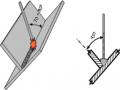
Fillet weld joint without bevel, welded on both sides. Discontinuous weld is performed by semi-automatic submerged arc welding method without backing plate, flux pad and pre-tacking.
|
|
| |
T-joint without bevel, welded on both sides. The weld is made by open circumferential manual arc welding method. Weld edge: K = 6 mm. |
|
|
|
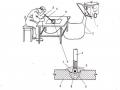
Butt weld joint of two parts on one side. The weld is made by automatic welding under flux layer using steel backing plate. |
|
|
|
Lap joint without bevel. Single-sided welding. The weld is made by semi-automatic welding method without backing, flux pad or pre-tacking. Weld edge: K = 5 mm. |
|
|
|


Butt weld joint of both parts on one side. Single-sided welding. The weld is made by manual arc welding.
|
|
|

1.2. Standard symbols of some countries:
1.2.1. British Standard BS.4871
According to this standard, the basic welding positions in manual arc welding are denoted as follows:
Face down: D
Horizontal welding: X
Korean standing from bottom up: V u Korean standing from top down: V d Korean standing from ceiling: O
- Other positions are also specified as follows: Weld (1G, 1F) for welding position D
Weld (2G, 2F) for X welding position Weld (4G, 4F) for O welding position
Weld (3G, 3F) for welding positions V u and V d
1.2.2. German standard DIN 1912
The basic welding position when arc welding is denoted as follows: PA(W) – prone welding
PB(h) – horizontal welding in prone position PC(q) – horizontal welding in standing position PE (u) – overhead welding
PF (s) – vertical welding from bottom up PG (f) – vertical welding from top down
1.2.3. Conventional welding symbols according to AWS standards
1.2.3.1. General provisions:
- Weld symbols: Welds are drawn with basic lines for both hidden welds, including the following symbols:
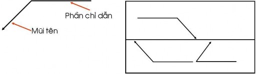
- Referenced object:
1.2.3.2. Additional symbols in welding :
Welding Symbols
TT Types of welds
Arrow side
The other side of the arrow
Both sides
1
Fillet weld
2
Butt weld without bevel
3
V-shaped butt weld
4
One-sided bevel butt weld


5
U-shaped butt weld | |||||||||||
6 | J-bevel butt weld | ||||||||||
7 | Flared V-groove butt weld | ||||||||||
8 | Butt weld flared edge | ||||||||||
9 | Groove weld or stud weld | N/A | |||||||||
10 | Spot weld or convex welding | N/A | |||||||||
11 | Weld seam | N/A | |||||||||
12 | Weld with backing pad or backing plate | N/A | |||||||||
13 | Weld Build-Surface | N/A | N/A | ||||||||
14 | Flange edge weld | N/A | |||||||||
15 | Angle flange weld | N/A |