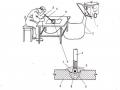
1.2.2. Principle
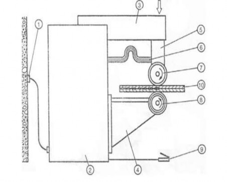
Figure 1.20 Schematic diagram of spot welding machine
1. Power outlet
2. Welding power source
3. Upper stand
4. Bottom bracket
5. Pressure generating unit
6. Power cable
7. Upper electrode disc
8. Lower electrode disc
9. Actuator pedal
10. Welding material
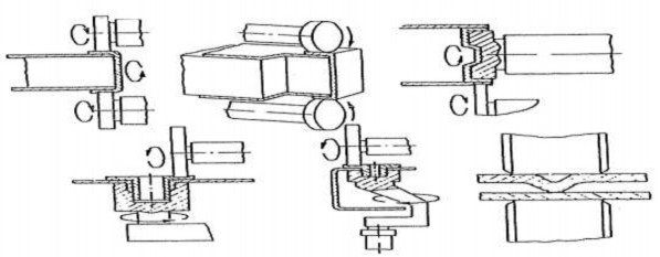
Figure 1.21. Electrode structure for seam welding
This welding method is used to join overlapping metal sheets by placing them between two electrodes with discs 7, 8 and continuously performing welding points to form a weld line by supplying current and applying pressure from the pressure generating unit. The current can be supplied continuously or intermittently.
If supplied continuously, a boost current is required to supplement the current to the weld pool.
- In line welding, in addition to the welding current, we need to have preliminary pressure and pressure throughout the welding process. The welding current passes through the welding object through the electrode. Unlike spot welding, the pressure only works when there is current running through it, which means that the electrode will separate from the welding object when the welding process is finished (the welding current is cut off).
- The welding process is continuous, so the following welding points are preheated to increase the metal volume limit to reach the molten state before welding. Then the metal is cooled, under the effect of pressure until the weld is strong enough to hold the two parts together. The welding current density and pressure must be large enough to ensure the creation of a weld (nugget) but not too high otherwise the molten metal will overflow from the welding area. The welding time is short enough to prevent heat from forming on the electrode surface. Because it can stick the electrode to the welding object, reducing the working life of the electrode. The required temperature of this welding process depends on the resistance when the current passes through the welding object. Because the short circuit current passes through the welding object and limits the welding time. When the welding current is high, it means the temperature at the welding spot is high.
Welding lines can be divided into two types: 1 - Continuous welding lines
2 - Intermittent welding
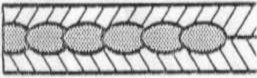
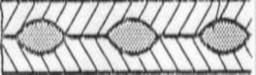
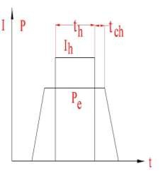
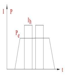
Figure 1.22. Continuous seam welding, Intermittent seam welding
1.2.3. Characteristics and applications of welding lines
- Simple, durable, beautiful and tight weld.
- Used to manufacture low carbon steel, stainless steel, hot-durable steel, light alloy parts with thickness from 0.1 - 1.5 mm.
- In some cases it is possible to weld up to 2mm thickness (soft low carbon steel).
- Scope of application in industries: Automobile manufacturing, refrigeration equipment, consumer goods...
- Limitation: Thickness of welding material
Table 1.6 Material thickness limitations
Material
Maximum thickness mm | |
Abrasion resistant steel | 2 + 2 |
Hot rolled low carbon steel | 1.75 + 1.75 |
Stainless steel, heat resistant steel | 1.5 + 1.5 |
Brass, copper bar | 1.2 + 1.2 |
Aluminum alloy | 1.5 + 1.5 |
Maybe you are interested!
-
 Low Carbon Steel Welding Rod Symbol According to Japanese Standards (Jis).
 -
 Practice Exercise 2: Welding “T” Corner Without Chamfer 2 Carbon Steel Plates Using Gmaw Welding Method At 3F Position (S=10Mm)
 -
 Design of single-phase and three-phase electric meter test bench - 10
 -
 Practical Exercise No. 2: Butt Welding in Upside Down Position 4G with Chamfered Edge of Steel Plate with Thickness S= 10 mm.
 -
 Number of Years Single Mothers Worked in Binh Duong
a
Main types of welds
nv/p
nv/p
P
P
Figure 1.23. Main types of welds
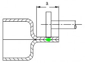
Overlap weld | |
Liquid containers (benzine, gasoline, oil, etc.). Advantage - Arrange the welding object outside the welding machine to avoid cross (cut) welds. - Ensure welding conditions on the entire weld circumference so that the weld quality is even across the entire weld. Defect Because the blank must be stamped, a large press must be used, so it is only suitable for mass production, etc. Request : - The width of the hem a mm depends on the thickness. S = 1 mm : a = 12 mm 1.5 16 2.0 18 If the weld is small, it can squeeze the molten metal to one side, causing local thinning of the part, thereby reducing the strength of the weld. Normal spot weld thickness welding near 2S |
Get wide application in industry. a min = 12 18 mm Weld thickness is close to 2S To flatten the weld, we often use the following measures: - Use wide roller on narrow weld (hb), a=(1.5 2)S. - Welding with pads. - Use filler wire placed on the weld. All of the above measures do not completely guarantee the quality of the weld, usually not exceeding 50% of the strength of the base material. When welding narrow welds cause significant wear on the electrode roller. Use pads and filler wire to facilitate the welding process. |

Butt weld
Seam welding is often used to manufacture cylindrical parts. When welding cylindrical parts, the most complicated part is the intersection. When not heated enough, it will create a gap and not be tight.
Figure 1.24. Cylindrical welding joint
1.2.4 Basic parameters of seam welding mode.
Seam welding can be continuous or intermittent: Continuous welding: The current flows continuously
Intermittent welding: Using pulse current.
Basic parameters
- Step of welding points: t = 1.5 4.5 mm, step increases with increasing thickness. To achieve tightness, it is necessary to ensure that adjacent welding points intersect each other not less than
0.5 weld point diameter.
When tightness is not required, the step t can be increased.
Sometimes, due to the increase in the dwell time between successive pulses of current, the step increases beyond the diameter of the welding spot and we get the line-spot welding method. This is also a high-productivity method of spot welding when using a line welder.
- The diameter of the adjacent spot determines the width of the weld, usually 3 8 mm. It depends on the thickness S of the welded material, the working width of the roller and the welding mode: 3 8 mm. In normal welding mode, the diameter of the welding spot is equal to or slightly smaller than the working width of the roller.
- The pressure exerted has an influence on the welding process such as spot welding. The maximum required force is related to the durability of the roller.
-Durability is increased when:
Use special electrode alloy with high hardness and conductivity (Cr bronze).
Increase roller path
Increase roller cooling (best to cool directly on the weld).
- Roller diameter D = 200 250 mm
Can reduce D = 150 mm but wears quickly, reducing durability.
D should not be reduced to < 150 mm except in the case of welding small parts where the rollers wear out very quickly.
The shape of the working part of the roller can be:
bb = 4-8 mm

Cylindrical: Usually used to weld steel with b = 4-8 mm. Then the plastic deformation at the welding point is reduced a little compared to the spherical shape.
When welding difficult welds, use a roller tilted to one side.
- Welding time:
When welding intermittently t = t h + t ng t h : Time of one pulse;
t ng : Rest time.
t 0.06a
v
; a : Step mm ; V: Welding speed mm/s
Score
t depends on welding material, usually from 0.15 0.7
t
This ratio decreases as the electrical and thermal conductivity of the material increases. This happens when welding in pulse mode with high current.
Large current with small step break results in incomplete heating of the workpiece surface and roller, causing rapid roller wear and poor weld surface.
Welding speed:
V = 0.5 3 m/min
V increase leads to increased welding productivity but increased welding machine power.
- Welding current intensity I h : 20 80% higher than spot welding
1.2.5. Calculate welding mode
Comparing spot welding between two conical electrodes and seam welding between two fixed rollers, it can be affirmed that there is no difference in principle between these two processes.
Contact welding can be considered as spot welding where the points are continuously distributed close to each other.
Thus, the welding current will branch very strongly, so it is necessary to consider the welding capacity when welding lines compared to spot welding of parts of the same thickness.
But the welding mode commonly used today is also experimental documents.
Seam welding is similar to spot welding.
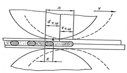
Figure 1.25. Welding diagram and welding point size
Roller compression force depends on welding material:
- Welding of carbon steel and Duyara:
P = 500 + 2000.S ( 1.13 )
- Welding stainless steel, hot-durable steel, titanium requires compression force at least twice as large as carbon steel.
Depending on the quality of the assembly and the strength of the welded structure, the pressing force may differ by 10% from formula (1.13).
In formula (1.13) P is pressure in ( N )
- Thickness of welded part ( mm )
Welding time depends on the welding method and welding material. For example, intermittent seam welding time of energization
Steel C: t x = 0.04(1+S 2 )
Hot-durable steel: t x =0.03(1+S 2 ) (1.14) Dura: t x = 0.02(1+S 2 )
S - Thickness of weld ( mm );
t x - time of energization ( s ).


The energizing time is t x , the disconnecting time is t d between pulses with the relationship: Steel C  = 0.5
= 0.5
Hot-durable steel:  =0.4 (1.15)

Density: =0.15 0.35
We assume that the fixed roller can only weld 1 welding point with diameter dT . In reality , the roller moves at speed v ( Figure 1.26 ), so the weld will be longer, the width is the width of the roller, the length of the weld is n .
n = d T + v T = d T + vt x (1.16) The size of this point overlapping another point is K which can be calculated as:
K = d T - vt d (1.17)
To ensure sufficient durability, K is usually equal to 1.1
5 4
and (2.17) we get the contact welding speed:
length n . From formula (1.16)
v 3d T
t x 4 t d
(1.18)
The welding line current is calculated as in spot welding. The branch circuit current for welding lines is quite complicated to calculate accurately, so people calculate it approximately using the following formula:
I n I
3S
cb d
(1.19)
T
In addition, we can also choose the welding mode for each type of material according to the table.
1.2.6. Welding technology of some materials
1.2.6.1. Low carbon steel welding technology
Low carbon steels and especially soft acid corrosion resistant steels with C < 0.12%, which have considerable ductility and electrical conductivity, are welded better than any other welding method.
Discontinuous welding of any thickness gives better results than continuous welding although continuous welding of thickness S  1 mm is used under production conditions. Cold rolled steel may not be cleaned before welding. When welding intermittently the time of each electric pulse is about (50
  70)% of the total welding cycle time. When welding low carbon steels any automatic welding equipment with reliable adjustment can be used.
Table 1.7 Low Carbon Steel Contact Welding Mode (Single Phase AC)
Thickness of limb
welding section [mm]
Welding current I [kA] | Welding time t [s] | Welding speed V h [m/min] | Compressive force F e [kN] | |
0.5 + 0.5 | 7 8 | 0.02 0.04 | 1 1.2 | 1.5 2 |
0.8 + 0.8 | 8.5 10 | 0.04 0.06 | 0.9 1 | 2 3 |
1.0 + 1.0 | 10.5 12 | 0.06 0.08 | 0.8 0.9 | 3 4 |
1.2 + 1.2 | 12 13 | 0.08 0.10 | 0.7 0.8 | 4 5 |
1.5 + 1.5 | 13 14.5 | 0.12 0.14 | 0.6 0.7 | 5 6 |
2.0 + 2.0 | 15.5 17 | 0.16 0.18 | 0.5 0.6 | 7 8 |
3.0 + 3.0 | 18 20 | 0.24 0.32 | 0.4 0.5 | 9 10 |