ADDITIONAL METALS
PRACTICE RESULTS ASSESSMENT FORM
Skill: Welding 2 carbon steel plates in “T” shape using GMAW welding method in climbing position - 3F (S=5mm)
Student's full name: ................................................... Student code: .........................................
Class: ......................... Group number: ...................... Implementation date: ......./......../ 20 ......
5
7 250
50
7 250
GMAW-3F
5
48
100
TT
Weld line | Joint parameters [mm] | Score Rating | |||||
k | Variable angle | Deviated edge | On fire foot | Student | Teacher | ||
1 | |||||||
1 | |||||||
Maybe you are interested!
-
 T-Bevel Welding Technique Without Bevel Position:
 -
 Practical Exercise No. 2: Butt Welding in Upside Down Position 4G with Chamfered Edge of Steel Plate with Thickness S= 10 mm.
 -
 Enforcement of fines from practice in District 2, Ho Chi Minh City - 8
 -
 Crime of rape of people under 16 years old from the practice of Soc Trang province - 10
 -
 Characteristics of the Practice of the Right to Prosecute During the Investigation Stage of a Case of Intentionally Causing Injury or Harm to the Health of Another Person.
INSTRUCTOR
(Sign, print full name)
STUDENTS PERFORMED
(Sign, print full name)
Point
Total score / number of evaluation factors = / = points | ||||
Point range | 85÷100 | 65÷85 | 25÷49 | Under 24 |
Rating Code | A | B | C | D |
2.1.5. Score evaluation guide
Content
main
Review section | Number of points deducted | |||
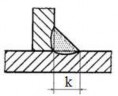
Fillet weld | Weld edge k = 7
| 7 Z 8 | 5<Z < 7 or 8 < Z < 9 | 7 Z 8 |
0 | 2 points/1 disability | 6 VND/1 disability | ||
Design thickness a = 5
| 5 a 6 | 6 < a 7 or 4 a < 5 | Other | |
0 | 2 points/1 disability | 6 VND/1 disability | ||
Weld edge deviation
| h 2 | h > 2 | ||
0 | Minus 2 points/1mm (from the 3rd mm deviation onwards) | |||
Convexity of weld (h)
| h 3 | h > 3 | ||
0 | 4 points/1 disability | |||
Burned weld toe | Depth of burn marks on legs <0.5 | A disability | From the second disability | |
0 | 2 points/1 disability | |||
Depth of burn marks on legs <1 | A disability | From disability Monday | ||
4 | 6d/1 disability | |||
Depth of burn marks on legs >1 | A disability | From disability Monday | ||
8 | 10d/1 defect disability | |||
Porosity on the weld surface | Do not have | A disability | From disability Monday | |
0 | 4 | 8 VND/1 disability | ||
Transition between weld seams of the overlay weld | Depth ≤ 1 | Depth ≤ 1.5 | Depth > 1.5 | |
0 | 2 points/1 disability | 4 points/1 disability | ||
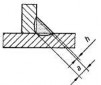
Welded joint with angular deformation | ≤ 5 0 | >5 0 | ||
0 | 4 points/ 10 deviations | |||
Surface product | Metal splatter on the surface | Removed completely | Other | |
product | 0 | 1 point/1 particle with diameter ≥ 0.25 | ||
Mechanical destruction | Do not have | A disability | From disability Monday | |
0 | 2 | 3 points/1 disability | ||
Some definitions:
1. Defect: is a short defect whose total length is not greater than 25mm in any 100mm of weld length or equal to 25% for welds with length less than 100mm.
2. End of weld recess: is the size from the bottom of the recess to the surface of the weld.
3. Single air leak: is an air leak that can have 1 or more air holes in which the distance between 2 air holes is smaller than the diameter of the small air hole.
2.2. Practical exercise 2: Welding “T” corner without bevel on 2 carbon steel plates using GMAW welding method at position 3F (S=10mm)
2.2.1. Preparation
1. Read drawings
10
10 250
50
10 250
GMAW-3F
10
10
10
45
100
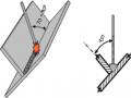
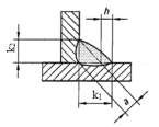
Figure 42. 1. Welded joint
Base plate width: 100 mm; Wall plate height: 50 mm Thickness of 2 panels: 10 mm
Wall panel is inserted into the middle of the base plate. Weld edge: 10 mm. Weld length: 250 mm. Vertical welding position: 3F.
2. Equipment and tools in GMAW welding
- Device
Semi-automatic welding machine in protective gas environment: MAXI COMPACT 322 GMAW welding accessories set
- Other equipment and tools
Hand grinder, wire cutters, slag hammer, wire brush. Welding goggles, leather gloves, non-stick grease.
3. Welding blank
Carbon Steel CT31
Size: 250×50×10; and 250×100×10 Quantity: 02 embryos/student/case
Requires flattening and cleaning the area to be welded about 15 ÷ 20mm
50 |
25010
Figure 42. 2. Wall panels
100 |
25010
Figure 42. 3. Base plate
4. Welding materials
Welding wire ER-70S – 6; 1.0 Shielding gas: CO 2
5. Other accessories
- Electrical conduit
Hole diameter: 1.0 Specification: short type
Length: 20mm
Thread size: M6 or M8
- GMAW welding torch gas cap
Size: 12 ÷ 16 mm
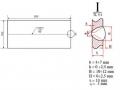
6. Measuring and testing equipment
Square, width and height measuring ruler, gauge, ruler,...
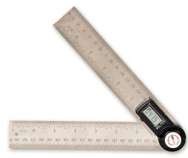
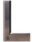
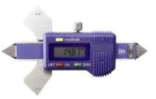
Figure 42. 4. Measuring and testing tools
2.2.2. Welding techniques.
1. Welding mode
a. First side
- First weld
Welding current: I h = 90 100 [A] Welding voltage: U h = 17 19 [V] Shielding gas flow: 12 liters/minute
- Second weld
Welding current: I h = 90 130 [A] Welding voltage: U h = 18 21 [V] Shielding gas flow: 12 liters/minute
- Third weld
Welding current: I h = 80 120 [A] Welding voltage: U h = 18 21 [V]
Shielding gas flow: 12 liters/minute
b. Second side
Use the same parameters and welding mode as the first side.
2. Tack welding to create blanks
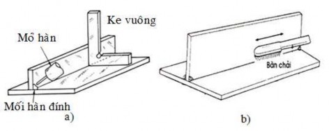
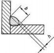
Figure 42. 5. Tack welding to create blanks (a); Cleaning the weld blanks after tacking (b) Requirements:
The joint must be strong and not come loose during welding. After welding, the part must not be warped or deformed.
After attachment, the blank must form a 90 0 angle . Weld the opposite side of the attachment.
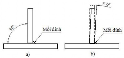
Figure 42. 6. Welded workpiece after attachment
(a). Use clamps when welding; (b) Do not use clamps when welding.
3. Mount the workpiece in the correct welding position
The workpiece is mounted in a vertical welding position (3F) to ensure stability during welding.
4. Welding torch angle
In case the material has thickness S=10 mm, edge k = 10 mm, we weld 2 layers. Angle
Liner welding torch: Travel angle =15 25 o ; Working angle =45 o . Similarly with the second layer.
5. Soldering iron oscillation
Triangular oscillating lining The second layer we use oscillating type
sawtooth (Figure 42.6)
7. Welding direction
Weld from bottom up
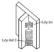
Figure 42.7. Oscillation pattern during multi-layer climbing welding
After welding the first weld, let the weld piece cool down to about 200 o C before welding the second weld.
6. Cleaning and inspection after welding
- Clean
After welding, we clean the weld with a wire brush.
- Check
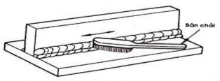
Figure 42. 8. Cleaning the weld
Visual inspection is intended to provide a preliminary assessment of external defects in the weld joint.
Check with angle gauge
Destructive (fracture) or non-destructive (ultrasonic) testing is also possible.
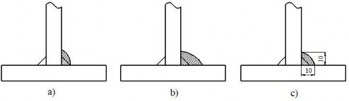
Figure 42. 9. Failed weld (a, b); Qualified weld (c)
2.2.3. Common defects, causes and prevention.
TT
Disability | Reason | Precautions | ||
1 | Burnt weld | - I big - Oscillation does not stop at two amplitudes | have points | - Adjust welding current accordingly - Stop at two oscillation amplitudes |
2 | Liquid splatter | needle | - High wire speed - Welding voltage is too high - Electrode protrusion is too long - Dirty or rusty welding wire | - Adjust the wire speed accordingly - Adjust the voltage accordingly - Adjust again (12 ÷ 18) mm - Clean and dry the welding wire |
3 | Weld edge not up to standard | - High welding speed - Width fluctuates or is too large | too small | - Adjust welding speed - Adjust the width to fit |
2.2.4. Welding process parameter table

UNIVERSITY | Lesson number: 04 - 2 |
NAM DINH UNIVERSITY OF TECHNICAL EDUCATION FACULTY OF MECHANICAL ENGINEERING – DEPARTMENT OF WELDING MECHANICS | WPS No: 04 - 2 | ||||||
WELDING PROCEDURE SPECIFICATION SHEET (WPS) | Day: | ||||||
BASIC MATERIALS | WELDING METHOD | ||||||
Applicable standards | TCVN 1765-75 | GMAW GTAW SMAW | |||||
Name | CT31 | TYPE | |||||
Thickness | 10mm | Semi-automatic Manual Automatic | |||||
ADDITIONAL METALS | JOINT TYPE | ||||||
Apply to welding layer | All | ||||||
Applicable standards | AWS 5.1 | ||||||
Symbol | ER70S-6 | ||||||
Diameter | 1.0 mm | ||||||
Trade name | Nam Trieu | ||||||
Flux welding wire | N/A | ||||||
Diameter | N/A | Welding position | 3F | ||||
Type of welding flux | N/A | Welding direction | Bottom up | ||||
Tungsten Electrode | N/A | Back cushion | N/A | ||||
Electrode diameter | N/A | Cushion material | N/A | ||||
PROTECTIVE GAS | Bottom hole | N/A | |||||
Gas type | Ingredient | Traffic | Bottom gouging method | N/A | |||
Shielding gas | CO 2 | 98% | 12 l/min | WELDING TECHNIQUE | |||
Trailing | N/A | N/A | N/A | Welding process | GMAW | ||
Backing | N/A | N/A | N/A | Oscillate | Have | ||
PREHEATING | Air cap size | 12 16 mm | |||||
Heating temperature | Ambient temperature | Clean the weld | Brush/grinding/slag grinding | ||||
Heating method | N/A | Protrusion of electrode | 12 18 mm | ||||
Interlayer temperature | N/A | Welding 1 or more layers | 2 layers | ||||
Testing method | Thermometer | Number of electrodes | 01 | ||||
POST WELD HEAT TREATMENT | CHARACTERISTICS OF ELECTRODES | ||||||
Temperature range | N/A | Welding process | GMAW | ||||
Time | N/A | Welding current type | DC | ||||
Cooling rate | N/A | Polarity | DCEP | ||||
Heating speed | N/A | Displacement form | N/A | ||||
Road (layer) welding | Too welding process | Electrode | Welding mode | ||||
Symbol | Road glasses | Type current | Current welding [A] | Voltage [V] | Welding speed (cm/min) | ||
1.1 | GMAW | ER70S-6 | 1.0 | DCEP | 80 100 | 17 19 | 20 30 |
1.2 | GMAW | ER70S-6 | 1.0 | DCEP | 90 130 | 18 21 | 20 30 |
1.3 | GMAW | ER70S-6 | 1.0 | DCEP | 90 130 | 18 21 | 20 30 |
2.1 | GMAW | ER70S-6 | 1.0 | DCEP | 80 100 | 17 19 | 20 30 |
2.2 | GMAW | ER70S-6 | 1.0 | DCEP | 90 130 | 18 21 | 20 30 |