+ Subjective appearance
Scoring section content | Minus points | Note | |
The surface, height and edge of the weld are uneven. | 2.0 |
Maybe you are interested!
-
 Practice Exercise 2: Welding “T” Corner Without Chamfer 2 Carbon Steel Plates Using Gmaw Welding Method At 3F Position (S=10Mm)
 -
 Improving the law on gender equality in the civil, marriage and family fields - Theoretical and practical issues - 1
 -
 Practical Application, Problems, Limitations and Causes
 -
 Theoretical and Practical Basis for Sustainable Tourism Development
 -
 Theoretical and Practical Basis of Employee Job Satisfaction
Note:
1. Defect: is a short defect whose total length is not greater than 25mm in any 100mm of weld length or equal to 25% for welds with length less than 100mm.
2. End of weld recess: is the size from the bottom of the recess to the surface of the material.
weld.
3. Single air hole: is an air hole that can have 1 or more air holes in which the distance between
between 2 small air holes is smaller than the diameter of the small air hole.
3.3. Practical exercise 2: Butt welding in the 4G position with beveled edge of steel plate with thickness S= 10 mm.
3.3.1.Implementation sequence
1. Read drawings and technical requirements of welds
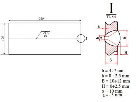
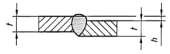
Figure 3.6. Weld drawing
2. Prepare equipment and tools
- Prepare MIG/MAG welding machine,
- Prepare the CO2 gas bottle and install the meter on the gas bottle, connect the gas pipe from the bottle to the machine.
- Pull rod, wire brush grinder, file, anvil, hammer, ruler, wrench
3. Prepare welding materials
- Prepare the welding wire. Insert the wire into the machine and adjust the length of the protruding part of the welding wire: 12÷ 15 mm
- Prepare gas, open valve to check the amount of gas in the bottle
- Welding blank: Cut steel blank, straighten and flatten. Clean the edge to be welded by filing or grinding.
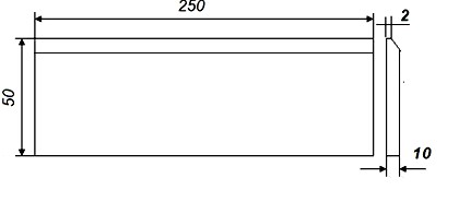
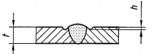
Figure 3.7 . Welding workpiece size
4. Determine and select welding parameters
- Adjust welding current: 120 ÷150 A, voltage 20 ÷22 V
- Adjust the protective gas flow rate to 10÷12 liters/minute
- Check the circulation of shielding gas: Press the soldering iron switch to check.
5. Fixing and attaching joints
- Place the workpiece on the fixture and adjust the gap to 3 ÷ 4 mm.
- The attachment must be sufficient to connect the welding workpiece, the size and attachment position must meet technical requirements and not affect the welding process and weld quality.
6. Mount the workpiece in the correct welding position
- The welding workpiece must be securely mounted in the correct 4G upside down welding position.
7. Adjust the welding mode parameters
- Adjust welding current to about: 100 ÷ 105 A, voltage 20 ÷ 22 V
- Adjust the protective gas flow rate to 10÷12 liters/minute
8. Welding the lining:
- Welding torch tilt angle: =90 o ~ 115 o ; = 90 o
- The soldering iron swings horizontally in a sawtooth or semicircular pattern, depending on the width of the mounting gap.
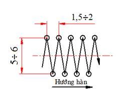
Fig.3.8. Sawtooth oscillation
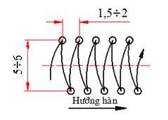
Fig.3.9. Semicircular oscillation
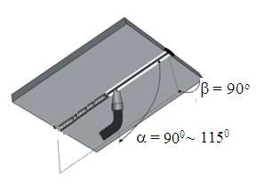
Figure 3.10. Welding torch angle
- Welding: In case you have to stop welding and then continue welding, use a grinder to thin the last weld pool, create an arc 10 ÷ 15 mm from the end point, and weld over the ground part. When you see the last point melt, move the welding torch in the same way as before.
- Before welding the last section of each weld, we grind the end point of the weld.
9. Clean and inspect the first weld (lining)
- Clean the weld: Use a hammer to pound the slag, then use a wire brush to clean the weld until it is bright white.
10. Adjust the welding mode parameters of the next layers
Based on material thickness and welding wire diameter, select and adjust welding parameters according to the welding parameter table on the machine.
- Adjust welding current to about: 100 ÷ 110 A, voltage 22 ÷ 24 V
- Adjust the protective gas flow rate to 12÷ 15 liters/minute
11. Welding the next layers:
- Welding torch tilt angle: =90 o ~ 115 o ; = 90 o
- Sawtooth or semicircular oscillation method
12. Cleaning and inspection
- Clean the weld: Use a hammer to pound the slag, then use a wire brush to clean the weld until it is bright white.
- Check the weld by naked eye and measure the sample to evaluate the appearance of the weld.
weld
13. Submit welding assignment
- Students number their own weld products and submit them to the teacher.
3.3.2. Welding procedure instruction sheet
Steps | Note | |
1 | Prepare welding machine, MIG/MAG welding torch | |
2 | Prepare tools: Pull rod, grinder, wire brush, file, anvil, hammer, ruler, wrench | |
3 | Prepare welding wire, Ar/CO 2 gas cylinder | |
4 | Adjust the protruding length of the welding wire tip: 12-15 mm | |
5 | Mount the meter on the Ar/CO 2 gas cylinder. | |
6 | Cut the welding blank according to the exact size of the drawing | |
7 | Straighten, straighten welding blank | |
8 | Clean the weld edge (grind or file) | |
9 | Adjust the current according to the welding parameter table. | |
10 | Adjust the flow of protective gas (8-12) liters/minute | |
11 | Check the gas cap, the circulation of the protective gas | |
12 | Clamp fixture at position 2G | |
13 | Adjust welding current according to welding parameter table | |
14 | Weld the first weld - Welding torch tilt angle: =90 o ~ 115 o ; = 90 o - Oscillation method: sawtooth | |
15 | Clean the first weld after welding. | |
16 | Check the shielding gas circulation, gas hood and electrical conduit | |
17 | Welding the second weld: Same technique as step 14 | |
18 | Cleaning the solder paste: As in step 15 | |
19 | Check the appearance of the weld with a gauge and the naked eye. to make a preliminary assessment of the quality of the weld | |
20 | Register and submit |
STT
3.3.3 . Common errors, causes and remedies
TT
Name | Illustration | Reason | How to fix | |
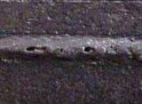
1 | Burnt edge weld. |
| - High welding speed, the welding torch has no stopping point at two amplitudes. - Large welding current | Adjust the speed moderately, oscillation has a stop point at two amplitudes. Do not choose too large current. |
2
Metal spatter |
| - Long arc, unstable current | - Shorten the arc distance. Adjust the current appropriately. | |
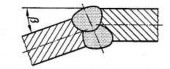
3 | Weld without fusion |
| Small current, fast welding head movement speed | Adjust welding current and speed appropriately |
4 | Unfilled metal top edge |
| - The angle of the soldering iron is not correct. | - Adjust the angle and oscillation of the soldering iron |
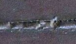
5 | Air holes |
| - Air flow is not guaranteed - Impact of wind from the outside environment | - Increase protective air flow - Avoid being blown by the wind when welding |
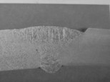
6 | Sagging | - Slow welding speed - Large welding current | - Increase speed - Reduce current intensity |


3.3.4. Instructions for evaluating results
STT
Review content | Point | |
1 | Time | 94.0 |
2 | Operational attitude | |
3 | Objective external score | |
4 | Subjective external appearance score | 6.0 |
Total | 100 |
+ Time
Standard time | Difference from standard time | Points deducted | Note | |
60 | > 5% (3 minutes) | No rating |
+ Attitude, action
- In case the lecturer determines that he/she has violated one of the following grading criteria, points will still be deducted.
- In a scoring item, if the number of violations > 2 times, the minus points will be counted as 2 times and only need to remind the candidate to avoid making more mistakes.
Item
Scoring section content | Points deducted | |
1 | In case of dropping welding pliers, arc short circuit | 2 |
2 | When not to use protective glasses when grinding and shaping welding slag | 5 |
3 | In case of inappropriate protective clothing | 5 |
4 | In case of unsafe behavior (including cases where the candidate suffers minor injuries due to his/her own negligence) | 5 |
5 | Moderate damage to machinery and equipment. | 5 |
6 | In case the steps are not followed correctly when starting the device | 5 |
7 | In case of not following the steps to close the device at the end | 5 |
8 | In case of no industrial cleaning after the exam is finished | 5 |
9 | In case of cutting welding wire with length greater than 5mm | 2 |
+ Objective appearance
Nine content
Review section | Number of points deducted | |||
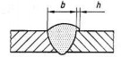
Weld width | b=(12÷13) | |||
b=[13÷15] | Or | b>18 | ||
b=(15÷18] | ||||
Face | 0 | 2 points /1mm in range | 4 points /1 mm | |
cover | b = 14 | |||
Weld height | 0 < h < 3 | h = [3÷ 6] | h > 6 | |
0 | 4 points/1 disability | 8 points / 1 disability | ||
h = 2.5 | |||
Overflow
| h ≤ 1 | 1 < h ≤ 2 | h > 2 |
0 | 2 points/1 defect | 4 points/1 disability | |
Leave foot
| A disability | From the second disability | |
5/1 disability | 7/1 disability | ||
Surface hollow
| h ≤ 0.5 | 0.5 < h ≤ 1 | h > 1 |
2 points/1 defect | 4 points/1 disability | 6 points/1 disability | |
Angular deformation
| β ≤ 5 0 | β > 5 0 | |
0 | Minus 2 points/10 ( from 6th degree deviation onwards) | ||
Offset
| h ≤ 1 | h > 1 | |
0 | Minus 2 points/1mm (from the 2nd mm deviation onwards) | ||
Weld end | h ≤ 1 | h > 1 | |
0 | Minus 2 points/1mm (from the 2nd mm deviation onwards) | ||
Burned weld toe
| Depth of burn marks on legs <0.5 | A disability | From the second disability |
0 | 2 points/1 defect | ||
Depth of burn mark < 1 | A disability | From the second disability | |
4 | 6 points/1 disability | ||
Depth of burn mark > 1 | A disability | From the second disability | |

8 | 10 points / 1 disability | |||
Surface transition between welds
| Depth of burn mark < 0.5 | A disability | From the second disability | |
0 | 2 points / 1 disability | |||
Depth of burn mark < 1 | A disability | From the second disability | ||
4 | 6 points / 1 disability | |||
Depth of burn mark > 1 | A disability | From the second disability | ||
8 | 10 points / 1 disability | |||
Slag
| Do not have | A disability | From the second disability | |
0 | 4 points | 8 points/1 disability | ||
Air holes
| Do not have | A disability | From the second disability | |
0 | 4 | 8 points / 1 disability | ||
Bottom face | Base weld leg
| Do not have | A disability | From the second disability |
0 | 5 | 7 | ||
Back convexity
h = 2 | h < 3 | h = [3÷ 6] | h > 6 | |
0 | 5 points / 1 disability | 8 points / 1 disability | ||
Bottom surface | Disability, h ≤ 0.5 | Disability, 0.5< h ≤ 1 | Disability, h > 2 | |
0 | 2 | 5 |