Compressor level, determines the overall condition of the compressor.
c. Record the compressor specifications in a notebook, notebook, or compressor log.
2.2.2. Open compressor addition:
a. Prepare open compressor.
b. Drain oil.
c. Remove the suction valve flange bolts.
d. Remove the push valve flange bolts.
e. Remove the tripod bolts.
f. Take the machine out.
g. Repair damage.
2.2.3. Disassemble and repair the open compressor mechanical part: Place the disassembled compressor in the repair position.
Remove the cover. Mark the location. Take the mechanism out of the case.
Remove, check, and treat the push tube gasket. Remove, check, and treat the valve cover assembly. Remove, check, and clean the oil line. Check, clean the crankshaft.
Check and clean bearings, battery, connecting rod. Check and clean piston, cylinder. Clean all parts. Lubricate before assembly.
The assembly sequence is the reverse of the disassembly sequence. Pour new oil into the machine. Check and test run.
* Note: Do not thin the valve blades or reverse the valve blades, and clean the oil filter.
2.2.4. Change compressor oil:
a. Drain all old oil;
b. Determine the correct type of oil and viscosity of the oil (for weak compressors, it is necessary to replace the oil with a thicker viscosity). The oil must be pure, without dirt or moisture.
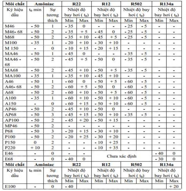
c. Determine the oil refill level (For the first refill, the amount of oil refilled is equal to the amount of oil poured out plus 1/5 of that amount) or according to the following table 1,2.
d. Place the oil tray in position.
e. Discharge the charging line.
f. Close the suction valve
g. Run the compressor.
h. Open the oil fill valve.
i. Close the oil filling valve when the oil is almost empty.
k. Open the suction valve.
l. Check for oil shortage or enough (Let the compressor run a few times and cover it tightly with your hand).
Push the tip and occasionally release compressed air onto a glass plate. If you see small oil particles sticking to the glass surface ⇨ enough oil. If you see large oil particles ⇨ excess oil, pour some out.
2.2.5. Shut down the machine and perform industrial cleaning. Table 1. Amount of oil to be filled for some types of
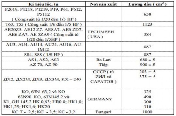
Table 2. Oil selection for piston compressors
(Orientation for selecting oil for piston compressors according to the lowest (min) and highest (max) evaporation temperature t 0 C )
*Practical exercises for students:
1. Prepare equipment, tools and materials.
2. Grouping:
Each group of 3-4 students practices on 1 type of open compressor, then rotates to another type of open compressor, trying to arrange for diversity to ensure a minimum of 01 compressor of each type for each group of students.
3. Perform general and specific procedures.
*Requirements for assessment of learning outcomes
Target
Content | Point | |
Knowledge | Draw the schematic diagram of an open compressor; describe the functions of the parts in the machine. - Describe the working principle of the compressor specific opening | 4 |
Skill | - Operate refrigeration compressors according to procedures to ensure refrigeration safety; - Name the main equipment of the compressor, record the technical parameters of the compressor, read correct values | 4 |
Attitude | Be careful, listen, take notes, take it easy, do it good industrial hygiene | 2 |
Total | 10 | |
Maybe you are interested!
-
 Basic Refrigeration Refrigeration and Air Conditioning Engineering - Intermediate - Ha Nam Vocational College 2020 - 1
 -
 Power Electronics Refrigeration and Air Conditioning Engineering - College - Dong Thap Vocational College - 16
 -
 Power Electronics Air Conditioning and Refrigeration Engineering - College - Dong Thap Vocational College - 1
 -
 Refrigeration Safety Course Profession: Refrigeration and air conditioning engineering - College - Dong Thap Vocational College - 2
 -
 Design and calculation of 3-phase asynchronous motor with Squirrel Cage rotor - 1
* Memorize:
1. Analyze the functions of the components in an open compressor; Scope of application of the machine.
2. Distinguish the parts of an open compressor and how it operates specifically.
of the parts.
1.2. Semi-hermetic compressor:
1.2.1. Definition:
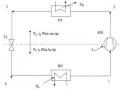
Semi-hermetic compressors have motors mounted in the compressor housing. The refrigerant chamber seals are all gasketed seals, tightened to the machine body with bolts. The machine is equipped with suction valves, discharge lines, and oil eyes. Figure 2.9.a,b,c,d shows the construction principle of semi-hermetic compressors, which often use countercurrent compressors.
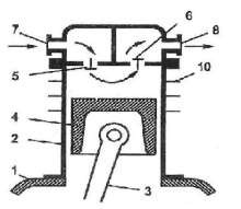
Figure 2.9.a. Construction principle of counter-current vertical piston compressor 1: Machine body; 6: Discharge valve
2: Cylinder 7: Suction line
3: Connecting rod 8: Push line
4: Piston; 5: Intake valve 10: Radiator fin
1.2.2. Working principle:
The suction valve is not arranged on the top of the piston, so the piston is simple, compact, and can increase speed. The suction and discharge valves are arranged on the cylinder cover, and the top of the cylinder cover is divided into two separate suction and discharge chambers.
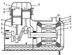
Figure 2.9.b. Construction principle of semi-hermetic compressor.
1: Crankshaft 8: Rotor
2: One-piece cylinder block 9: Stator
3: Connecting rod 10: Intake port
4: Piston 11: Engine tank cap
5: Inner cover 12: Coil
6: Suction valve 13: Top cover
7: Push valve 14: Sealing gasket
The motor of the semi-hermetic compressor is located inside the compressor housing. When the motor is running, it will directly drive the compressor crankshaft. Thanks to the connecting rod, the rotary motion will be converted into the reciprocating motion of the piston inside the cylinder, performing the suction, compression and emptying of the refrigerant vapor;
The refrigerant vapor after passing through the electric motor cooling coil will enter the suction chamber on the side of the cylinder and then enter the cylinder through the suction valve. When the piston moves back and forth in the cylinder, the volume limited by the cylinder and the piston surface changes, creating the suction and compression processes. The piston moves from the top dead center to the bottom dead center, the volume increases to the maximum, the suction valve opens to let the refrigerant vapor enter the cylinder. The piston moves in the opposite direction, the volume gradually decreases, starting the process of compressing and pushing the refrigerant vapor. At this time, both the suction and discharge valves are closed.
The compressor load reduction during start-up is performed automatically, the suction and discharge valves are in the fully open state;
Electric motors are cooled in two ways: refrigerant vapor or external cooling fan.
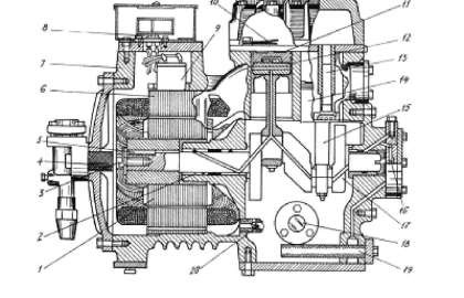
Figure 2.9.c. Structure of semi-hermetic compressor.
1: Engine rotor 11: Intake valve
2: Bearing bushing 12: Piston ring
3: Brake plate fixing the rotor to the motor 13: Check valve 4: Suction filter 14: Piston
5: Rotor key 15: Connecting arm
6: Stator 16: Oil pump
7: Engine body 17: Crankshaft
8: Electrical junction box 18: Oil level sight glass
9: Overcurrent relay 19: Oil filter
10: Push valve 20: Oil line check valve
1.2.3. Advantages, disadvantages and scope of application:
- Advantage:
+ The possibility of refrigerant leakage is reduced because there is no shaft seal assembly but only more secure static gaskets;
+ The machine size is smaller than open compressor, installation area is not large;
+ No transmission loss because the crankshaft is connected to the engine shaft;
+ Simple operation, safe, reliable, simple maintenance.
- Disadvantages:
+ Valve has small cross-section so pressure loss increases;
+ Only use for non-conductive media;
+ The cooling capacity cannot be adjusted because there is no stepless adjustment pulley, it can only be adjusted by level and the implementation is relatively complicated;
+ Repairing the motor is more difficult than with an open compressor;
+ High suction steam overheating if using suction steam to cool the engine.
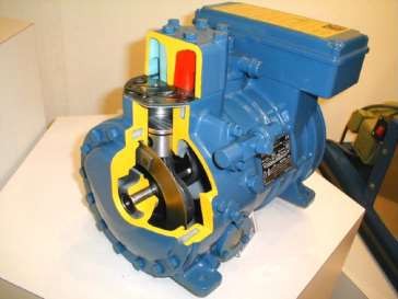
Figure 2.9.d. Principle of semi-hermetic compressor.
* Steps and methods of performing the work:
1. EQUIPMENT, TOOLS, MATERIALS:
(Calculated for a practice session of 20 students)
Equipment Type | Quantity | |
1 | All kinds of refrigeration compressors | 50 pcs |
2 | Specialized refrigeration tool kit | 20 sets |
3 | Clamp meter | 10 sets |
4 | Pipe bending set of all kinds | 10 sets |
5 | Flare set of all kinds | 10 sets |
6 | Wrenches of all kinds | 10 sets |
7 | O 2 – C 2 H 2 gas welding set | 5 sets |
8 | O2 gas welding set | 5 sets |
9 | Gas welding torch | 10 sets |
10 | Multimeter | 5 pcs |
11 | Megome watch | 2 pcs |
12 | Copper pipes of all kinds | 200 kg |
13 | Three-strap watch | 10 sets |
14 | Intake valve | 100 pieces |
15 | Welding rods of all kinds | 100 kg |
16 | Refrigerant oil, rags, wires, switches, circuit breakers, lights | 100 sets |
signal...... | ||
17 | Workshop | 1 |
TT

2. IMPLEMENTATION PROCESS: 2.1. General process: