head. Thus the object works in the elastic region. In this region, according to Hook's law, we have: The deformation of the object is proportional to the force causing the deformation.
- In fact, this hypothesis is only true for metals. The mathematical expression of Hooke's law has the following form:
- Single stress state – stretching along one axis
1
z E z
- Pure sliding state – only sliding deformation
1 .
XY G XY
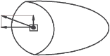
P
P
L
L
L
Figure 2.19
1.3 External force - Internal force - Stress
1.3.1 External force
Forces acting from the external environment or from other objects on the object under consideration are called external forces. External forces include impact loads and reaction forces at the connections. Based on the form of action, external forces are divided into concentrated forces and distributed forces.
- Concentrated force is the force acting on a small force transmission area, which can be considered a point on the object (force P)
- Distributed force is the force acting over a long distance or over a significant force transmission area of the object. (force q(z))
q(z)
P
Z
Compiled by: Ta Thi Hoang Than
Figure 2.2
1.3.2 Internal force
Under the influence of external forces, objects are deformed, the binding forces between the elements of the object increase to resist the deformation of the object. The increase in the binding force that resists the deformation of the object is called internal force. Depending on the type of material, internal force only increases to a certain limit. If the external force increases too much, the internal force is not strong enough to resist, the material will be damaged.
To determine internal forces, we use the cross-sectional method to consider a force-bearing object in a state of equilibrium. To find the internal force at a certain point C, we imagine using a plane passing through C, cutting the object into two parts A and B. Consider a certain part.
P 2
P 3
A
C
B
P 1
P 4
A
P 1
P 2
Figure 2.3
Figure 2.4
For example, consider part A, part A is in equilibrium under the effect of external forces acting on it (P 1 , P 2 ) and the mutual force system distributed on the cross-section acting from part B to part
A. That force system is the internal force on the cross section . From there, the internal force can be determined through the value of the external force in part A.
* Internal force components on cross section
To determine internal forces we must use the cross-sectional method.
MX
N Z
Q X
M
Q y
Y
Suppose we consider the equilibrium of the right part of the internal force system characterizing the effect of the left part on the right part represented by the vector P placed at a certain point K.
Z
K
X
R
Y
Z
X
Hoang Th
Figure 2.13
Figure 2.14
Compiled by: Ta Thi An
Reduce the resultant force P placed at point K to the center of gravity O of the cross-section. We will
R
R
get a force has vector equal to and a couple with moment M (main vector and
main moment of internal force system)
R
Force and M have arbitrary directions in space. For convenience, we divide
R is made into three components on a rectangular coordinate system chosen as shown in the figure.
- The component located on the Z axis is called the vertical force. Symbol N Z
- The component located on the X and Y axes in the cross section is called the shear force.
effect Q X , Q y .
The torque M is also divided into three components.
- The moment component rotating around the X, Y axes (acting in the ZOY and ZOX planes perpendicular to the cross-section) is called the bending moment: Symbols MX and MY .
- The torque component rotating around the X, Y axes (acting in the plane of the cross section) is called the torsional moment. Symbol M Z
- M Z , MX , MY , Q X , Q y , N Z are six internal force components on the cross section. They are determined from static equilibrium conditions to determine internal forces under the effect of external forces.
1.3.3 Stress
The value of internal force per unit area of the cross-section is called stress. The dimension of stress is N/cm 2 , KN/cm 2 , symbol is P
- Suppose we take a point C on the cross section of part A. We take an area F
contains C. On the area F, there is an internal force distributed with a resultant force with vector
P :
A
F
C
Figure 2.5
We have
P P
F tb
P tb is called the average stress at C
Direction of the vector
P is in the same direction as the vector
P . If F approaches zero then
P tb approaches a limit. That limit is called the total stress at point C. Symbol P .
P lim P
F
F 0
In calculation, total stress is divided into two components.
- The component perpendicular to the cross-section is called normal stress: symbol
- The component located in the cross section is called shear stress: Symbol is
2 2
Thus: P
The above analysis for A also applies to part B.
P
B
F C
Figure 2.6
From this we have the following convention on signs and how to write stress:
- Normal stress is considered positive when the vector represents the same direction as the positive normal outside the section. Symbol x
- Shear stress is considered positive when the external normal of the cross-section rotated 90 0 clockwise will coincide with the direction of shear stress.
xy
x
> 0 X
xy > 0
Y
Cross section
z
y
x
xz
Figure 2.7
Figure 2.8
y
Q
P
x
z
Figure 2.9
F
Shear stress is accompanied by two indices. The first index indicates the external normal direction, the second index indicates the shear stress direction.
* Stress state
If we consider different cross-sections through C, then corresponding to each different cross-section position, we get a vector P with a different value. The set of all stresses P corresponding to all cross-sections through C is called the stress state.
It has been proven that: Through a point we can always find three cross-sections perpendicular to each other. On those three cross-sections, the shear stress component = 0. Those cross-sections are called principal cross-sections, the stress on those cross-sections is called principal stress.
For the three main sides there are three cases
- Simple stress state: on one main surface there is normal stress. On the other two main surfaces the normal stress is 0.
- Plane stress state: on two main surfaces there is normal stress. On the remaining main surface the normal stress is 0
2
1
- Block stress state: on three main surfaces there is normal stress
2 3
1
1 1
Figure 2.10
Figure 2.11
Figure 2.12
- The principal stresses are conventionally 1 2 3
* Relationship between internal force and stress on cross section
Let the stress at any point M(X,Y) on the cross-section of the projection components of P be
- Normal stress z
- Shear stress is analyzed into two components ZX , ZY
Y
ZY
dF
Z
ZX
M(xy)
Take an elemental area dF surrounding M. The elemental forces due to the stresses are z , dF, ZX dF, ZY dF
X
Figure 2.15
The sum of all the effects of those elemental forces on the entire cross-section is the internal force components on the cross-section. From that meaning, we have the following expressions relating stress and internal force components.
N Z Z . dF
F
Q y ZY . dF
F
MX Z . YdF
F
M Y
Q X ZX . dF
F
Z . XdF
F
Mz ( ZY X ZX Y ) dF
F
- The circular cross-section at point M is divided into two components:
+ A component perpendicular to the radius is denoted by P
+ A component directed along the radius is denoted by r
We have:
M Z P dF
r
dF
M Z
F
Figure 2.16
2. PULL AND COMPRESS
2.1 Concept of tensile compression
2.1.1 Definition
A bar is said to be in tension or compression at the center when the cross-section of the bar has only one internal force component, the longitudinal force.
Nz > 0
Nz < 0
Figure 2.20
2.1.2 Internal force diagram
The internal force in a tensile or compressive bar is the longitudinal force Nz perpendicular to the cross-section.
P 11
L 11
P 1
P 1

Maybe you are interested!
-
 Developing a training program in mechanical engineering at the University of Industrial Technology - 15
 -
 Developing a training program in mechanical engineering at the University of Industrial Technology - 1
 -
 Diesel engine maintenance and repair - Automotive Technology Profession For College Level Part 1 - 1
 -
 Directing Innovation in Training Methods for Engineering Technology Industry According to Competency Approach
 -
 Tc Ch C Scientific Research Work on the Ministry of Science and Technology; Training of Cadres for the Ministry of Science and Technology; Organizing the National Conference on Science and Technology in the Central Highlands/City

5.10 4
P 2 2
L 22
N Z1
P 2
P 3
N Z2
2.10 4
Figure 2.21
- The internal force diagram is a line showing the variation of force along the axis of the bar.
- Sign convention:
+ Positive longitudinal force when the bar is under tension
+ Negative longitudinal force when the bar is compressed
Example 1: Draw the longitudinal force diagram of a load-bearing bar knowing P 1 = 5.10 4 N; P 2 = 3.10 4 ; P 3 = 2.10 4 .
To draw the graph, we divide the bar into two segments L 1 and L 2
- Consider section L 1 : using section 1-1 to examine the balance on the left, we have
Z P 1 N 1 0
P 1 =N 1 = 3.10 4 N
When the 1-1 cross section varies in the segment L 1 ( 0 Z 1 L 1 ) the longitudinal force N Z1 remains constant and equals 5.10 4 N
- Consider segment L 2 using cross-section 2-2 to examine the balance on the left: We have
Z P 1 N 2 0 N Z 2 P 1 P 2
N Z2 = 5.10 4 – 3.10 4 = 2.10 4 N
When the 2-2 section varies in the segment L 2 ( 0 Z 2 L 2 ) the longitudinal force N Z2 remains constant and equals 2.10 4
- The longitudinal force diagram along the entire length of the bar is shown in the figure. The abscissa represents the bar axis, the ordinate represents the longitudinal force corresponding to the cross-section on the bar axis.
2.1.3 Stress in tensile (compressive ) bar
Before a bar is loaded, we draw on the outside of the bar lines perpendicular to the bar axis representing the cross-sections and lines parallel to the bar axis representing the longitudinal fibers of the bar (Figure 2.21a).
b)
P
a)
Figure 2.21
When the pulling force P is applied, we can see that the lines perpendicular to the bar axis move downward, but remain straight and perpendicular to the bar axis. The lines parallel to the axis move closer together but remain straight and parallel to the bar axis (Figure 2.21b). From these observations, we can conclude:
When a bar is subjected to tension (compression):
- The cross sections remain straight and perpendicular to the bar axis.
- The longitudinal fibers of the bar with the same elongation remain straight and parallel to the bar axis.
Thus, the internal force distributed on the cross-section must be parallel to the axis of the bar (perpendicular to the cross-section), that is, on the cross-section there is only normal stress. On the other hand, because the longitudinal fibers have uniform elongation, the internal force is evenly distributed on the cross-section.
We denote the stress in tensile and compressive bars as k and n. The expression relating stress to internal force is as follows:
k,n
N
F
(+) sign if the bar is in tension, (-) sign if the bar is in compression.
2.1.4 Deformation, Hooke's law
2.1.4.1 Deformation:
Under the effect of tensile force P, the bar will lengthen but the width will narrow (Figure 2.22a) (the deformed bar is drawn with a dashed line). Under the effect of compressive force P, the bar will shorten but the width will increase (Figure 2.22b).