PART I. DESIGN OF ASYNCHRONOUS MOTORS 4
CHAPTER 1. WORKING PRINCIPLE AND STRUCTURE OF ASYNCHRONOUS ELECTRICAL MACHINES 4
I. General information about asynchronous machines 4
Maybe you are interested!
-
 Design of Linear Phase Fir Filter Using Window
 -
 Design of single-phase and three-phase electric meter test bench - 10
 -
 Design and construction of color TV PAN model - 2
 -
 Solutions for Investment Implementation Phase
 -
 Network design - Master Tran Van Long, Master Tran Dinh Tung Compiled - 24
II. Working principle of asynchronous motor 5
III. Structure of asynchronous motor 7
IV. Uses 8
V. Structure of electric machine 9
CHAPTER 2. GENERAL ISSUES IN DESIGNING SQUIRREL-CAGE ASYNCHRONOUS MOTORS 11
I. Advantages 11
II. Disadvantages 11
III. Remedial measures 12
IV. Comments 12
V. Engine manufacturing standards 12
VI. Design method 12
VII. Design content 12
VIII. Standards for squirrel cage asynchronous motors 12
IX. Design sequence 15
CHAPTER 3. CALCULATION OF Asynchronous Machines 17
I. Determine the main dimensions 17
II. Stator design 19
III. Rotor iron core design 21
IV. Air gap 22
V. Parameters of asynchronous electric motor during starting 23
PART II. DESIGN AND CALCULATION OF THREE-PHASE ASYNCHRONOUS MOTOR WITH SQUIRREL CAGE ROTOR 27
CHAPTER 1. MAIN DIMENSIONS 29
1. Number of pole pairs 29
2. Stator outer diameter 29
CHAPTER 2. WINDINGS, STATOR GAP AND AIR CLEARANCE 31
1. Steel code and steel sheet thickness 31
2. Stator structure of AC motor housing 31
4. Stator slot step 31
5. Number of effective conductor bars of a ur1 slot 31
6. Number of series turns of one phase 32
7. Cross section and diameter of conductor 32
8. Winding type 32
9. Winding factor 33
10. Air gap flux Ф 34
11. Air gap flux density Bδ and line load A 34
12. Preliminary determination of tooth width b'z1 34
13. Preliminary height of stator yoke hg1 34
14. Slot and insulation dimensions 34
15. Groove area minus wedgeS'r 35
16. Stator tooth width bz1 35
17. Stator yoke height 36
18. Air gap 36
CHAPTER 3. WINDINGS, SLOTS AND ROTOR YANGLES 37
1. Rotor slot number Z2 37
2. Rotor outer diameter D' 37
3. Rotor tooth pitch t2 37
4. Preliminary determination of rotor tooth width b'z2 37
5. Rotor shaft diameter Dt 37
6. Current in rotor bar Itd 37
7. Current in short circuit Iv 38
8. Cross section of aluminum round guide bar S'td 38
9. Preliminary selection of current density in short circuit Sv = 2.5 A/mm2 38
10. Rotor slot size and short circuit ring 38
11. Short circuit rim height hv 38
12. Average diameter of short circuit ring Dv 38
13. Short circuit rim width bv 38
14. Rotor slot area Sr2 38
15. Rotor tooth width at 1/3 tooth height 38
16. Rotor yoke height hg2 39
17. Make groove in rotor bn 39
CHAPTER 4. MAGNETIC CIRCUIT CALCULATION 40
1. Air gap coefficient 40
2. Use cold rolled KTĐ steel 2211 40
3. Air gap dynamic force Fδ 40
4. Magnetic flux density at stator teeth Bz1 40
5. Magnetoelectric force on stator teeth 40
6. Magnetic flux density at rotor teeth Bz2 41
7. Magnetic force on rotor teeth Fz2 41
8. Tooth saturation coefficient kz 41
9. Magnetic flux density on stator yoke Bg1 41
10. Magnetic field intensity at stator yoke Hg1: according to Table V-9 (Appendix V, page 611 TKMĐ), we choose 41
11. Magnetic circuit length at stator yoke Lg1 41
12. Magnetodynamic force at stator yoke Fg1 41
13. Magnetic flux density on rotor yoke Bg2 41
14. Magnetic field intensity at rotor yoke Hg2: according to Table V-9 (Appendix V, page 611 TKMĐ), we choose 41
15. Rotor yoke open circuit length Lg2 41
16. Magnetodynamic force at rotor yoke Fg2 42
17. Total magnetic force of magnetic circuit F 42
18. Full circuit saturation coefficient kµ 42
19. Magnetizing current Iµ 42
20. Magnetizing current percent 42
CHAPTER 5. ELECTRIC MOTOR PARAMETERS AT RATED OPERATION 43
1. Length of stator winding connector Lđ1 43
2. Average half turn length of stator winding ltb 43
3. Length of single phase winding of stator L1 43
4. Stator winding resistance r1 43
5. Active resistance of rotor winding rtd 43
6. Short circuit loop resistance rv 44
7. Rotor resistance r2 44
8. Conversion factor γ 44
9. Converted rotor resistance 44
10. Stator slot dissipation coefficient λr1 44
11. Stator dissipation coefficient 45
12. Dissipation coefficient of connector part λđ1 45
13. Stator dissipation coefficient 45
14. Stator winding resistance x1 45
15. Rotor slot dissipation coefficient λr2 45
16. Rotor dissipation coefficient 46
17. Dissipation coefficient of connector part 46
18. Dissipation coefficient due to inclined groove 46
19. Rotor dissipation coefficient 46
20. Rotor winding dissipation reactance 46
21. Converted rotor reactance 46
22. Mutual inductive reactance x12 46
23. Calculate kE 47
CHAPTER 6. STEEL LOSS AND MECHANICAL LOSS 48
1. ................................................ ................................................................ .............................................. 48
2. Stator yoke weight 48
3. Iron loss in stator iron core 48
4. Surface loss on rotor teeth 49
5. Pulsing loss on rotor teeth 49
6. Total steel loss 50
7. Muscle loss 50
8. No-load loss 50
CHAPTER 7. WORKING CHARACTERISTICS 51
1. Coefficient C1 51
2. Reactive component of current in synchronous mode 51
3. Active component of current in synchronous mode 51
4. Electromotive force E1 51
5. Rated slip coefficient 52
6. Slip coefficient at maximum moment 52
7. Maximum torque multiple 52
CHAPTER 8. CALCULATION OF STARTING CHARACTERISTICS 55
1. Parameters of electric motor when considering skin effect with s = 1 55
2. Parameters of electric motor when considering skin effect and saturation of magnetic circuit when s=1 56
4. Starting current 57
5. Starting current multiple 58
6. Starting torque multiple 58
CHAPTER 9 THERMAL CALCULATION 59
1. The heat sources on the heat substitution diagram include 59
2. Thermal resistance on stator iron core surface 60
3. Thermistor of stator winding connector 60
4. Thermal resistance characterizes the difference between the hot air inside the machine and the machine case 61
5. External surface thermal resistance of the machine case 61
6. Thermal resistance on groove insulation 62
7. Temperature difference between the case and the environment 63
8. Temperature rise of stator winding 63
CHAPTER 10. VENTILATION AND COOLING CALCULATIONS 64
I. Ventilation system 64
II. Ventilation calculation 65
1. Determine the amount of air needed 65
III. Fan calculation 66
1. Characteristics of centrifugal fan 66
2. Characteristics of centrifugal fan 66
1. Determine the amount of air needed Q 66
2. Maximum air consumption 67
3. Centrifugal fan calculation 67
4. Fan blade height 69
5. Number of blades 69
6. Fan size 69
7. Fan capacity Pq 70
CHAPTER 11. MECHANICAL CALCULATIONS 71
I. Calculation of axis 71
II. Select shaft size 72
2. Check shaft strength 72
3. Calculate the bearing position at ball 75
4. Select the case 76
5. Select the 76 machine cover
6. Overall dimensions and base of the machine according to Appendix I page 598 (TKMD) 77
7. Choose hanger 77
CHAPTER 12. QUANTITY OF ACTIVE MATERIALS AND USAGE INDICATORS 78
1. Weight of standard silicon steel b 78
2. Copper weight of stator winding 78
3. Rotor aluminum weight (excluding short-circuited rotor blades) 78
PART III
SAVE ELECTRIC ENERGY BY CONTROLING POWER FACTOR
RATE… 83
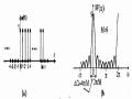
1.Power Factor Control- Basic Circuit Details… 83
2.Discontinuous Mode Amplifier Circuit To Continuous Mode For ControlPower Factor Correction 85
3.Input Voltage Stability In Continuous Mode Amplifier… 88 4.Output Stability In Continuous Mode Amplifier Stabilizer… . 89
PART 1. DESIGN OF ASYNCHRONOUS MOTORS
CHAPTER 1. WORKING PRINCIPLE AND STRUCTURE OF ASYNCHRONOUS ELECTRICAL MACHINES
I. General information about asynchronous machines
Asynchronous electric machines are widely used in the national economy due to their simple structure, sturdy operation, convenient use and maintenance, and low cost, especially those with a capacity of less than 100 kW.
The simplest structure of squirrel cage asynchronous electric motor is the cast aluminum squirrel cage rotor, so it accounts for a large number of small and medium capacity motors. The disadvantage of this motor is that it is difficult to adjust the speed and the large starting current is usually 6-7 times the rated current. To make up for this disadvantage, people manufacture multi-speed squirrel cage asynchronous motors and use deep groove rotors and double squirrel cages to reduce the starting current and increase the starting torque.
Asynchronous motor with wound rotor can adjust the speed to a certain extent, can create a large starting torque with not very large starting current, but is more difficult to manufacture than squirrel cage rotor, so the cost is higher, and maintenance is also more difficult.
Asynchronous electric motors are manufactured according to IP23 protection type and IP44 sealed type. Electric motors with IP23 protection type use radial fans placed at both ends of the electric motor rotor. In cast aluminum squirrel cage rotor motors, the aluminum fan blades are cast directly onto the short-circuit ring. Electric motors with IP44 protection type usually rely on the fan blades placed outside the machine casing to blow air on the outside of the machine casing, so the heat dissipation is worse than IP23 type but machine maintenance is easier.
Currently, countries have produced asynchronous electric motors according to standard series. The asynchronous motor series with capacity from 0.55-90 KW, denoted as K according to Vietnam standard 1987-1994, is recorded in table 10-1 (Page 228 TKMĐ). According to this standard, asynchronous electric motors in the series are manufactured according to IP44 type.
In addition to the above standards, there is also TCVN 315-85 standard, which regulates the capacity range of squirrel-cage asynchronous electric motors from 110 kW-1000 kW, including the following capacities: 110,160, 200, 250, 320, 400, 500, 630, 800 and 1000 kW.
The symbol of an asynchronous electric motor with a squirrel cage rotor is written according to the symbol of the name of the electric motor series, the symbol of the height of the rotating shaft center, the symbol of the installation size along the shaft and the symbol of the number of shafts.
II. Working principle of asynchronous motor
A three-phase asynchronous motor has two main parts: the stator (stationary part) and the rotor (rotating part). The stator consists of an iron core on which three-phase windings are located.
When connecting a three-phase winding to a three-phase grid, there will be currents running in the winding, this current system creates a rotating magnetic field, rotating at the speed of:
n 60 * f 1
1 p
In there:
-f 1 : power frequency
-p: number of magnetic pole pairs of the winding
The rotating part, located on the rotating shaft, consists of the rotor core. The rotor winding consists of a number of conductor bars.
placed in the grooves of the magnetic circuit, the two ends are connected by two short-circuit rings.
n 1 N 1
F dt
n 2
n 2
F dt
s 1
n 1
Figure 1.1
The rotating magnetic field of the stator induces an electromotive force E in the rotor wire, because the stator winding is closed, so there is a current flowing in it. The interaction between the current-carrying conductors and the magnetic field of the machine creates electromagnetic forces F acting on the conductors with a direction determined by the left-hand rule.
The set of forces acting on the conductor in a tangential direction to the rotor surface creates a rotor torque. Thus, we see that the electrical energy taken from the grid has been converted into mechanical energy on the motor shaft. In other words, an asynchronous motor is an electromagnetic device, capable of converting electrical energy taken from the grid into mechanical energy output on its shaft. The direction of rotation of the rotor is the direction of rotation of the magnetic field, so it depends on the phase sequence of the grid voltage applied to the stator winding. The speed of the rotor n 2 is the working speed and is always less than the speed of the magnetic field and only in that case does electromotive force induction occur in the rotor winding. The difference in rotational speed of the magnetic field and the rotor is characterized by a quantity called the slip coefficient s:
s n 1 n 2
n 1
When s=0 means n 1 =n 2 , the rotor speed is equal to the magnetic field speed, this mode is called ideal no-load mode (no resistance on the shaft). In real no-load mode, s 0 because there is a little wind resistance, friction due to bearings ...
When the slip coefficient is s=1, the rotor is stationary (n 2 =0), the torque on the shaft is equal to the starting torque.
The slip coefficient corresponding to the rated load is called the rated slip coefficient. The motor speed corresponding to this slip coefficient is called the rated speed.
Asynchronous motor speed is equal to:
n 2 n 1 * (1 s )
An important feature of the asynchronous motor is that the stator winding is not directly connected to the grid, the electromotive force and current in the rotor are obtained by induction, that is why this motor is also called an induction motor.
The frequency of the current in the rotor is very small, it depends on the speed of the rotor's slip relative to the magnetic field:
f p * n 1 n 2
p * n 1 * ( n 1 n 2 ) s * f
1
2 60 60 * n
1
An asynchronous motor can be operated as a generator if another motor is used to rotate it at a speed higher than the synchronous speed, while its outputs are connected to the grid. It can also be operated independently if its outputs are excited by capacitors.
Asynchronous motors can be made into single-phase motors. Single-phase motors cannot start by themselves, so to start a single-phase motor, starting elements such as capacitors, resistors, etc. are needed.
III. Structure of asynchronous motor
Asynchronous motors are divided into two types in terms of structure: short-circuit asynchronous motors, also known as squirrel-cage rotors, and wound motors. The stator has two similar types. In this thesis, only squirrel-cage asynchronous motors are studied.
1. Stator (static part)
The stator consists of a housing, a steel core and windings.
- Case
The machine casing is the place to fix the iron core, winding wire and at the same time is the place to join the cover or shaft bearing. The machine casing can be made of cast iron, aluminum or steel core. To manufacture the machine casing, people can cast, weld, forge. There are two types of machine casing: closed type casing and protective type casing. Closed type casing requires a large heat dissipation area, so people make many heat dissipation ribs on the surface of the machine casing. Protective type casing usually has a smooth outer surface, the cooling wind blows directly on the outer surface of the steel core and inside the machine casing.
The pole box is the place to hide the electricity from the grid. For closed type motors, the pole box must be sealed, between the pole box body and the machine shell and the pole box cover must have a rubber gasket. On the machine shell, there are also ring bolts to lift the machine when lifting, transporting and grounding bolts.
- Iron core
The iron core is the magnetic conductor. Because the magnetic field passing through the iron core is a rotating magnetic field, to reduce loss, the iron core is made of 0.5mm electrical engineering steel sheets pressed together. The requirement for the iron core is that it must conduct magnetic well, have small iron loss and be sturdy.
Each sheet of electrical steel is coated with insulating paint on the surface to reduce losses caused by eddy currents (limiting eddy currents).
- Winding wire
The stator winding is placed in the groove of the iron core and is well insulated from the iron core. The winding plays an important role in the electric machine because it directly participates in the process of converting electrical energy into mechanical energy or vice versa. At the same time, economically, the cost of the winding also accounts for a fairly high part of the total cost of the machine.
2. Rotating part (Rotor )
The rotor of an asynchronous motor consists of an iron core, windings and shaft (for wound motors there is also a slip ring).
- Iron core
The rotor iron core consists of electrical steel sheets like the stator, the difference here is that there is no need for insulating paint between the steel sheets because the operating frequency in the rotor is very low, only a few Hz, so the loss due to the hydraulic current in the rotor is very low. The iron core is pressed directly onto the machine shaft or onto a rotor stand of the machine. The outside of the steel core has grooves to place the rotor winding.
- Rotor winding
Divided into two main types: wound rotor type and squirrel cage rotor type
- Wound rotor type
The rotor has windings similar to the stator windings. Medium-sized and larger machines use double-layer wave windings, because there are fewer connecting wires and the winding structure on the rotor is tight. Small-sized machines use single-layer concentric windings. The three-phase windings of the rotor are usually connected in star formation.
The characteristic of wound type motor is that it can use carbon brush to introduce additional resistance or additional electromotive force into the rotor circuit to improve the machine's starting performance, adjust the speed or improve the machine's power factor.
- Squirrel cage rotor type
The structure of the winding is very different from the stator winding. In each slot of the rotor iron core, long copper or aluminum conductors are placed away from the iron core and are short-circuited at both ends by two copper or aluminum short-circuit rings. If the rotor is cast aluminum, there are also vortex blades on the short-circuit ring.
The copper rotor is made from high resistivity copper alloy to increase the starting torque.
To improve the starting performance, for large capacity machines, people make deep rotor grooves or use double squirrel cages. For small electric machines, the rotor grooves are made diagonally to the shaft center.
Squirrel cage windings do not need to be insulated from the iron core.
- Shaft
The shaft of the electric machine carries the rotor rotating in the stator cavity, so it is also a very important part. The shaft of the electric machine, depending on the size, can be made from Carbon steel from 5 to 45.
On the rotor shaft there are steel core, windings, slip ring and fan.
3. Gap
Since the rotor is a circular block, the clearance is uniform. The clearance in an asynchronous machine is very small (0.2 1 mm in small and medium sized machines) to limit the magnetizing current taken from the grid, thereby increasing the power factor of the machine.
IV. Uses
Asynchronous electric machines are electric machines mainly used as electric motors. Due to their simple structure, sturdy operation, high efficiency, low cost, easy maintenance, etc., asynchronous motors are the most widely used electric machines in the national economic sectors with capacities of several tens of W to tens of kW. In industry, asynchronous electric machines are often used as power sources for medium and small steel rolling mills, power for machine tools in light industrial factories, etc. In mines, they are used as irrigation machines or fans. In agriculture, they are used as pumps or agricultural processing machines. In daily life, asynchronous electric machines