A code word
a n , a n 1 ... a 1 a 0
in there
a i =0 can be expressed as a polynomial in the variable x
and the coefficients are a i . .
For example, the codeword 1001101 can be written as a polynomial:
1. x 6 0. x 5 0. x 4 1. x 3 1. x 2 0. x 1 1. x 0 x 6 x 3 x 2 1
At this point, we can perform ordinary algebraic operations with that polynomial. As for addition, it must be done according to mod 2, which means:
x a x a 0
a . x a 0 x a
0 0 0
To build cyclic codes, people use irreducible polynomials (cannot be reduced
be ) as a generating polynomial to construct the codes. Encryption method :
To be the information carrier element of the codeword, we choose the codewords of the full codeword with length m. This codeword is called the original codeword, denoted G(x). To form the cyclic codeword F(x), we
receive codeword G(x) with x K , where K is the number of residual elements. That means we lengthen the codeword
G(x) produces K more elements. Then divide the polynomial G(x). x K gives the generating polynomial P(x), then
Take the remainder R(x) plus the polynomial G(x).
F ( x ) G ( x ). x K R ( x ) .
F(x) will be divisible by the generating polynomial P(x)
x K , we will get the cyclic codeword:
According to this encoding, the mp elements with high exponents are the information carrying elements, while the remaining k elements with low exponents are the residual elements. Because the residual element and the message carrier element stand separately, the cyclic code is a type of delimiter code.
For example, let n=7
m=4 K=3
P ( x ) x 3 x 2 1 Let's encrypt message 1011 Solution:
Core
P ( x ) x 3 x 2 1 1101
G ( x ) x 3 x 1 1011
G ( x ). x K :
-------------------------------------------------- ------------------------------------------------- 57
============== Faculty of Electrical Engineering - Department of Automation ==============
G ( x ). x K ( x 3 x 1). x 3 x 6 x 4 x 3 1011000
divide
G ( x ). xK
P ( x )
x 6 x 4 x 3
x 3 x 2 1
x 3
x 2
x
x 3 x 2 1
1011000 110 100
1101 1101
Residual: R ( x ) x 2 100
We have the cycle codeword:
F ( x ) G ( x ). x K R ( x )
x 6 x 4 x 3 x 2 1 { 0111 { 00
mgtin du
A simple method to find cyclic codewords is the matrix method.
In this method, we use a displacement generation matrix P x . This matrix has m rows and n columns.
The leading edge is the polynomial G ( x ). xK
The rows after the exponent K decrease gradually to 0.
According to the example above, we can establish the displacement generation matrix as follows:
G ( x ). x K
G ( x ). x
P x m n L
K 1
G ( x ). x 1
G ( x ). x 0
1 | 0 | 1 | 0 | 0 |
1 | 1 | 0 | 1 | 0 |
0 | 1 | 1 | 0 | 1 |
0 | 0 | 1 | 1 | 0 |
Maybe you are interested!
-

 Car body electrical practice - 8
zt2i3t4l5ee
zt2a3gs
zt2a3ge
zc2o3n4t5e6n7ts
If the voltage is out of specification, replace the wire or connector.
If the voltage is within specification, install the front fog light relay and follow step 5.
Step 5 Check the front fog light switch
- Remove the D4 connector of the fog light switch
- Use a multimeter to measure the resistance of the front fog light switch.
Measurement location
Condition
Standard
D4-3 (BFG) -D4-4 (LFG)
Light switchFront Fog OFF
>10kΩ
D4-3 (BFG) -D4-4 (LFG)
Front fog light switchON
<1 Ω
- Standard resistor
D4 connector is located on the combination switch assembly.
If the resistance is out of specification, replace the combination switch (the fog light switch is located in the combination switch).
If the resistance is within specification, follow step 6.
Step 6 Check wiring and connectors (front fog light relay-light selector switch)
- Disconnect connector D4 of the combination switch assembly
- Use a voltmeter to measure the voltage value of jack D4 on the wire side.
Measurement location
Control modecontrol
Standard
D4-3 (BFG) - (-) AQ
TAIL
11 to 14 V
D4 connector for the wiring of the combination switch assembly
If the voltage does not meet the standard, replace the wire or connector.
If the voltage is within standard, there may have been an error in the previous measurements.
Step 7 Check the front fog lights
- Remove the front fog light electrical connector.
- Supply battery voltage to the fog lamp terminals
Jack 8, B9 of front fog lamp on the electrical side
blind first.
Power supply location
Terms and Conditions
Battery positive terminal - Terminal 2Battery negative terminal - Terminal 1
Fog lightsbefore morning
- If the light does not come on, replace the bulb.
If the light is on, re-plug the jack and continue to step 8.
Step 8 Check wiring and connectors (relay and front fog lights)
- Disconnect the B8 and B9 connectors of the front fog lights.
- Use a voltmeter to measure voltage at the following locations:
Measurement location
Switch location
Terms and Conditions
B8-2 - (-) AQ
Electric lock ON TAIL size switchFog switch ON
11 to 14 V
B9-2 - (-) AQ
Electric lock ONTAIL size switch Fog switch ON
11 to 14 V
B8 and B9 connectors on the front fog lamp wiring side
Voltage is not up to standard, repair or replace the jack. If up to standard, there may have been an error in the measurement process.
2.2.4. Procedure for removing, installing and adjusting fog lights 1. Procedure for removing
- Remove the front inner ear pads
Use a screwdriver to remove the 3 screws and remove the front part of the front inner ear liner
-Remove the fog light assembly
+ Disconnect the connector.
+ Use a screwdriver to remove 3 screws to remove the fog light cover
2. Installation sequence
-Rotate the fog lamp bulb in the direction indicated by the arrow as shown in the figure and remove the fog lamp from the fog lamp assembly.
-Rotate the fog light bulb in the direction indicated by the arrow as shown in the figure and install the light into the fog light assembly.
- Use a screwdriver to install the fog light cover
-Install the electrical connector
Attention: Be careful not to damage the plastic thread on the lamp assembly.
- Install the front inner ear pads
Use a screwdriver to install the front inner bumper with 3 screws.
3. Prepare the vehicle to adjust the fog light convergence. Prepare the vehicle:
- Make sure there is no damage or deformation to the vehicle body around the fog lights.
- Add fuel to the fuel tank
- Add oil to standard level.
- Add engine coolant to standard level.
- Inflate the tire to standard pressure.
- Place spare tire, tools and jack in original design position
- Do not leave any load in the luggage compartment.
- Let a person weighing about 75 kg sit in the driver's seat.
4. Prepare to check the fog light convergence
a/ Prepare the vehicle status as follows:
- Place the car in a dark enough place to see the lines. The lines are the dividing line, below which the light from the fog lights can be seen but above which it cannot.
- Place the car perpendicular to the wall.
- Keep a distance of 7.62 m between the center of the fog lamp and the wall.
- Park the car on level ground.
- Press the car down a few times to stabilize the suspension.
Note: A distance of approximately 7.62 m is required between the vehicle (fog lamp center) and the wall to adjust the convergence correctly. If the distance of 7.62 m cannot be achieved, set the correct distance of 3 m to check and adjust the fog lamp convergence. (Since the target area varies with the distance, please follow the instructions as shown in the figure.)
b/ Prepare a piece of thick white paper about 2 m high and 4 m wide to use as a screen.
c/ Draw a vertical line through the center of the screen (line V).
d/ Set the screen as shown in the picture. Note:
- Keep the screen perpendicular to the ground.
- Align the V line on the screen with the center of the vehicle.
e/Draw the reference lines (H, V LH and V RH lines) on the screen as shown in the figure.HINT:
Mark the center of the fog lamp on the screen. If the center mark cannot be seen on the fog lamp, use the center of the fog lamp or the manufacturer's name mark on the fog lamp as the center mark.
H line (fog light height):
Draw a line across the screen so that it passes through the center mark. Line H should be at the same height as the center mark of the fog light bulb.
Line V LH, V RH (center mark position of left fog lamp LH and right fog lamp RH):
Draw two lines so that they intersect line H at the center marks.
5. Check the fog light convergence
a/ Cover the fog lamp or remove the connector of the other side fog lamp to prevent light from the unchecked fog lamp from affecting the fog lamp convergence test.
b/ Start the engine.
c/ Turn on the fog lights and make sure that the dividing line is outside the standard area as shown in the drawing.
6. Adjust the fog light convergence
Use a screwdriver to adjust the fog light to the standard area by turning the toe adjustment screw.
Note: If the screw is adjusted too far, loosen it and then tighten it again, so that the last rotation of the light adjustment screw is clockwise.
3. Self-study questions
1. Describe the operating principle of the lighting system with automatic headlight function
2. Describe the operating principle of the lighting system with the function of rotating headlights when turning
3. Draw diagram and connect lighting system on Hyundai Porter car
4. Draw diagram and connect lighting system on Honda Accord 1992
5. Draw the lighting circuit on a 1993 Toyota Lexus
LESSON 3 MAINTENANCE AND REPAIR OF SIGNAL SYSTEM
I. IMPLEMENTATION GOAL
After completing this lesson, students will be able to:
- Distinguish between types of signals on cars
- Correctly describe common symptoms and suspected areas causing damage.
- Connecting signal circuits ensures technical requirements
- Disassemble, install, check, maintain and repair the signal system to ensure technical requirements.
- Ensure safety in work and industrial hygiene
II. LESSON CONTENT
1. General description
The signal system equipped on cars aims to create signals to notify other vehicles participating in traffic about the vehicle's operating status such as: stopping, parking, braking, reversing, turning...
Signals are used either by light such as headlamps, brake lights, turn signals….. or by sound such as horns, reverse music….
Just like the lighting system. A signal system circuit usually consists of: battery, fuse, wire, relay, electrical load and control switch. Only some switches of the signal system are on the combination switch. The switches of other signals are usually located in different locations such as in the gearbox or brake pedal……
2. Maintenance and repair
2.1. Turn signals and hazard lights
The installation location of the turn signal is shown in Figure 3.1. The turn signal control switch is located in the combination switch under the steering wheel. Turning this switch to the right or left will make the turn signal turn right or left.
The hazard light switch is used when the vehicle has a problem while participating in traffic. When the hazard light switch is turned on, all the turn signals on the vehicle will light up at a certain frequency. The hazard light switch is usually placed separately from the turn signal switch (some old cars integrate the hazard and turn signal switches on the same combination switch cluster).
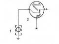
Figure 3.1 Turn signal switch Figure 3.2 Hazard switch
The part that generates the flashing frequency for the lights is called a turn signal relay. The turn signal relay usually has 3 terminals: B (positive power supply); E (negative power supply); L (providing the turn signal switch to distribute to the
lamp)
2.1.1. Circuit diagram
To generate the frequency for the turn signal, a turn signal relay is used in the turn signal circuit. The current from the turn signal relay will be sent to the turn signal switch assembly to distribute the current to the turn signal lights for the driver's purpose.
Figure 3.3. Schematic diagram of a turn signal circuit without a hazard switch
1. Battery; 2. Electric lock; 3. Turn signal relay; 4. Turn signal switch; 5. Turn signal lamp; 6. Turn signal lamp; 7. Hazard switch
Figure 3.4 Schematic diagram of turn signal circuit with hazard switch
1. Battery; 2. Combination switch cluster; 3. Turn signal;
4. Turn signal light; 5. Turn signal relay
Today's cars no longer use three-pin turn signal relays (B, L, E) but use eight-pin turn signal relays (figure 3.5) (pin number 8 is used for hazard lights).
For this type, the current supplying the turn signal lights is supplied directly from the turn signal relay to the lights.
div.maincontent .p { color: black; font-family:"Times New Roman", serif; font-style: normal; font-weight: normal; text-decoration: none; font-size: 14pt; margin:0pt; } div.maincontent p { color: black; font-family:"Times New Roman", serif; font-style: normal; font-weight: normal; text-decoration: none; font-size: 14pt; margin:0pt; } div.maincontent .s1 { color: black; font-family:"Times New Roman", serif; font-style: normal; font-weight: normal; text-decoration: none; font-size: 13pt; } div.maincontent .s2 { color: black; font-family:"Times New Roman", serif; font-style: italic; font-weight: normal; text-decoration: none; font-size: 14pt; } div.maincontent .s3 { color: black; font-family:"Times New Roman", serif; font-style: normal; font-weight: normal; text-decoration: none; font-size: 14pt; } div.maincontent .s4 { color: black; font-family:"Times New Roman", serif; font-style: normal; font-weight: normal; text-decoration: none; font-size: 13pt; } div.maincontent .s5 { color: black; font-family:"Times New Roman", serif; font-style: normal; font-weight: normal; text-decoration: none; font-size: 13pt; vertical-align: 1pt; } div.maincontent .s6 { color: black; font-family:"Times New Roman", serif; font-style: normal; font-weight: normal; text-decoration: none; font-size: 11pt; } div.maincontent .s7 { color: black; font-family:"Times New Roman", serif; font-style: normal; font-weight: normal; text-decoration: none; font-size: 14pt; vertical-align: -9pt; } div.maincontent .s8 { color: black; font-family:"Times New Roman", serif; font-style: normal; font-weight: normal; text-decoration: none; font-size: 11pt; } div.maincontent .s9 { color: #008000; font-family:"Times New Roman", serif; font-style: normal; font-weight: normal; text-decoration: none; font-size: 14pt; } div.maincontent .s10 { color: black; font-family:"Times New Roman", serif; font-style: italic; font-weight: normal; te
Car body electrical practice - 8
zt2i3t4l5ee
zt2a3gs
zt2a3ge
zc2o3n4t5e6n7ts
If the voltage is out of specification, replace the wire or connector.
If the voltage is within specification, install the front fog light relay and follow step 5.
Step 5 Check the front fog light switch
- Remove the D4 connector of the fog light switch
- Use a multimeter to measure the resistance of the front fog light switch.
Measurement location
Condition
Standard
D4-3 (BFG) -D4-4 (LFG)
Light switchFront Fog OFF
>10kΩ
D4-3 (BFG) -D4-4 (LFG)
Front fog light switchON
<1 Ω
- Standard resistor
D4 connector is located on the combination switch assembly.
If the resistance is out of specification, replace the combination switch (the fog light switch is located in the combination switch).
If the resistance is within specification, follow step 6.
Step 6 Check wiring and connectors (front fog light relay-light selector switch)
- Disconnect connector D4 of the combination switch assembly
- Use a voltmeter to measure the voltage value of jack D4 on the wire side.
Measurement location
Control modecontrol
Standard
D4-3 (BFG) - (-) AQ
TAIL
11 to 14 V
D4 connector for the wiring of the combination switch assembly
If the voltage does not meet the standard, replace the wire or connector.
If the voltage is within standard, there may have been an error in the previous measurements.
Step 7 Check the front fog lights
- Remove the front fog light electrical connector.
- Supply battery voltage to the fog lamp terminals
Jack 8, B9 of front fog lamp on the electrical side
blind first.
Power supply location
Terms and Conditions
Battery positive terminal - Terminal 2Battery negative terminal - Terminal 1
Fog lightsbefore morning
- If the light does not come on, replace the bulb.
If the light is on, re-plug the jack and continue to step 8.
Step 8 Check wiring and connectors (relay and front fog lights)
- Disconnect the B8 and B9 connectors of the front fog lights.
- Use a voltmeter to measure voltage at the following locations:
Measurement location
Switch location
Terms and Conditions
B8-2 - (-) AQ
Electric lock ON TAIL size switchFog switch ON
11 to 14 V
B9-2 - (-) AQ
Electric lock ONTAIL size switch Fog switch ON
11 to 14 V
B8 and B9 connectors on the front fog lamp wiring side
Voltage is not up to standard, repair or replace the jack. If up to standard, there may have been an error in the measurement process.
2.2.4. Procedure for removing, installing and adjusting fog lights 1. Procedure for removing
- Remove the front inner ear pads
Use a screwdriver to remove the 3 screws and remove the front part of the front inner ear liner
-Remove the fog light assembly
+ Disconnect the connector.
+ Use a screwdriver to remove 3 screws to remove the fog light cover
2. Installation sequence
-Rotate the fog lamp bulb in the direction indicated by the arrow as shown in the figure and remove the fog lamp from the fog lamp assembly.
-Rotate the fog light bulb in the direction indicated by the arrow as shown in the figure and install the light into the fog light assembly.
- Use a screwdriver to install the fog light cover
-Install the electrical connector
Attention: Be careful not to damage the plastic thread on the lamp assembly.
- Install the front inner ear pads
Use a screwdriver to install the front inner bumper with 3 screws.
3. Prepare the vehicle to adjust the fog light convergence. Prepare the vehicle:
- Make sure there is no damage or deformation to the vehicle body around the fog lights.
- Add fuel to the fuel tank
- Add oil to standard level.
- Add engine coolant to standard level.
- Inflate the tire to standard pressure.
- Place spare tire, tools and jack in original design position
- Do not leave any load in the luggage compartment.
- Let a person weighing about 75 kg sit in the driver's seat.
4. Prepare to check the fog light convergence
a/ Prepare the vehicle status as follows:
- Place the car in a dark enough place to see the lines. The lines are the dividing line, below which the light from the fog lights can be seen but above which it cannot.
- Place the car perpendicular to the wall.
- Keep a distance of 7.62 m between the center of the fog lamp and the wall.
- Park the car on level ground.
- Press the car down a few times to stabilize the suspension.
Note: A distance of approximately 7.62 m is required between the vehicle (fog lamp center) and the wall to adjust the convergence correctly. If the distance of 7.62 m cannot be achieved, set the correct distance of 3 m to check and adjust the fog lamp convergence. (Since the target area varies with the distance, please follow the instructions as shown in the figure.)
b/ Prepare a piece of thick white paper about 2 m high and 4 m wide to use as a screen.
c/ Draw a vertical line through the center of the screen (line V).
d/ Set the screen as shown in the picture. Note:
- Keep the screen perpendicular to the ground.
- Align the V line on the screen with the center of the vehicle.
e/Draw the reference lines (H, V LH and V RH lines) on the screen as shown in the figure.HINT:
Mark the center of the fog lamp on the screen. If the center mark cannot be seen on the fog lamp, use the center of the fog lamp or the manufacturer's name mark on the fog lamp as the center mark.
H line (fog light height):
Draw a line across the screen so that it passes through the center mark. Line H should be at the same height as the center mark of the fog light bulb.
Line V LH, V RH (center mark position of left fog lamp LH and right fog lamp RH):
Draw two lines so that they intersect line H at the center marks.
5. Check the fog light convergence
a/ Cover the fog lamp or remove the connector of the other side fog lamp to prevent light from the unchecked fog lamp from affecting the fog lamp convergence test.
b/ Start the engine.
c/ Turn on the fog lights and make sure that the dividing line is outside the standard area as shown in the drawing.
6. Adjust the fog light convergence
Use a screwdriver to adjust the fog light to the standard area by turning the toe adjustment screw.
Note: If the screw is adjusted too far, loosen it and then tighten it again, so that the last rotation of the light adjustment screw is clockwise.
3. Self-study questions
1. Describe the operating principle of the lighting system with automatic headlight function
2. Describe the operating principle of the lighting system with the function of rotating headlights when turning
3. Draw diagram and connect lighting system on Hyundai Porter car
4. Draw diagram and connect lighting system on Honda Accord 1992
5. Draw the lighting circuit on a 1993 Toyota Lexus
LESSON 3 MAINTENANCE AND REPAIR OF SIGNAL SYSTEM
I. IMPLEMENTATION GOAL
After completing this lesson, students will be able to:
- Distinguish between types of signals on cars
- Correctly describe common symptoms and suspected areas causing damage.
- Connecting signal circuits ensures technical requirements
- Disassemble, install, check, maintain and repair the signal system to ensure technical requirements.
- Ensure safety in work and industrial hygiene
II. LESSON CONTENT
1. General description
The signal system equipped on cars aims to create signals to notify other vehicles participating in traffic about the vehicle's operating status such as: stopping, parking, braking, reversing, turning...
Signals are used either by light such as headlamps, brake lights, turn signals….. or by sound such as horns, reverse music….
Just like the lighting system. A signal system circuit usually consists of: battery, fuse, wire, relay, electrical load and control switch. Only some switches of the signal system are on the combination switch. The switches of other signals are usually located in different locations such as in the gearbox or brake pedal……
2. Maintenance and repair
2.1. Turn signals and hazard lights
The installation location of the turn signal is shown in Figure 3.1. The turn signal control switch is located in the combination switch under the steering wheel. Turning this switch to the right or left will make the turn signal turn right or left.
The hazard light switch is used when the vehicle has a problem while participating in traffic. When the hazard light switch is turned on, all the turn signals on the vehicle will light up at a certain frequency. The hazard light switch is usually placed separately from the turn signal switch (some old cars integrate the hazard and turn signal switches on the same combination switch cluster).
Figure 3.1 Turn signal switch Figure 3.2 Hazard switch
The part that generates the flashing frequency for the lights is called a turn signal relay. The turn signal relay usually has 3 terminals: B (positive power supply); E (negative power supply); L (providing the turn signal switch to distribute to the
lamp)
2.1.1. Circuit diagram
To generate the frequency for the turn signal, a turn signal relay is used in the turn signal circuit. The current from the turn signal relay will be sent to the turn signal switch assembly to distribute the current to the turn signal lights for the driver's purpose.
Figure 3.3. Schematic diagram of a turn signal circuit without a hazard switch
1. Battery; 2. Electric lock; 3. Turn signal relay; 4. Turn signal switch; 5. Turn signal lamp; 6. Turn signal lamp; 7. Hazard switch
Figure 3.4 Schematic diagram of turn signal circuit with hazard switch
1. Battery; 2. Combination switch cluster; 3. Turn signal;
4. Turn signal light; 5. Turn signal relay
Today's cars no longer use three-pin turn signal relays (B, L, E) but use eight-pin turn signal relays (figure 3.5) (pin number 8 is used for hazard lights).
For this type, the current supplying the turn signal lights is supplied directly from the turn signal relay to the lights.
div.maincontent .p { color: black; font-family:"Times New Roman", serif; font-style: normal; font-weight: normal; text-decoration: none; font-size: 14pt; margin:0pt; } div.maincontent p { color: black; font-family:"Times New Roman", serif; font-style: normal; font-weight: normal; text-decoration: none; font-size: 14pt; margin:0pt; } div.maincontent .s1 { color: black; font-family:"Times New Roman", serif; font-style: normal; font-weight: normal; text-decoration: none; font-size: 13pt; } div.maincontent .s2 { color: black; font-family:"Times New Roman", serif; font-style: italic; font-weight: normal; text-decoration: none; font-size: 14pt; } div.maincontent .s3 { color: black; font-family:"Times New Roman", serif; font-style: normal; font-weight: normal; text-decoration: none; font-size: 14pt; } div.maincontent .s4 { color: black; font-family:"Times New Roman", serif; font-style: normal; font-weight: normal; text-decoration: none; font-size: 13pt; } div.maincontent .s5 { color: black; font-family:"Times New Roman", serif; font-style: normal; font-weight: normal; text-decoration: none; font-size: 13pt; vertical-align: 1pt; } div.maincontent .s6 { color: black; font-family:"Times New Roman", serif; font-style: normal; font-weight: normal; text-decoration: none; font-size: 11pt; } div.maincontent .s7 { color: black; font-family:"Times New Roman", serif; font-style: normal; font-weight: normal; text-decoration: none; font-size: 14pt; vertical-align: -9pt; } div.maincontent .s8 { color: black; font-family:"Times New Roman", serif; font-style: normal; font-weight: normal; text-decoration: none; font-size: 11pt; } div.maincontent .s9 { color: #008000; font-family:"Times New Roman", serif; font-style: normal; font-weight: normal; text-decoration: none; font-size: 14pt; } div.maincontent .s10 { color: black; font-family:"Times New Roman", serif; font-style: italic; font-weight: normal; te -
 Accounting for revenue, expenses and business results at Tien Phat Electrical Engineering Company Limited - 15
 -
 Accounting for consumption and determining business results at Dang Gia Phat Electrical Engineering Company Limited - 10
 -
 Electrical safety textbook for industrial electricity at college level - Vietnam - Korea Vocational College, Hanoi city - 4
 -
 Car body electrical practice - 11

1
P ( x ) 4 7
0
0
0
0 a 1
0
a 2
0 a 3
1
4
a
m 4
n 7
Cyclic code words found = combination between rows
a 1 a 2 a 3 a 4
of matrix P ( x ) .
According to the above example, we have m=4 so the number of code words available for the cyclic code is now: N 2 m 2 4 16 code words
Omitting the first zero codeword, we have 15 codewords left, which are:
Codeword 1: a 1 1101000
-------------------------------------------------- ------------------------------------------------- 58
============== Faculty of Electrical Engineering - Department of Automation ==============
0110100 | |
3 : a 3 | 0011010 |
4 : a 4 | 0001101 |
5 : a 1 a 2 | 1011100 |
6 : a 1 a 3 | 1110010 |
7 : a 1 a 4 | 1100101 |
8 : a 2 a 3 | 0101110 |
9 : a 2 a 4 | 0111001 |
10 : a 3 a 4 | 0010111 |
11: a 1 a 2 a 3 | 1000110 |
12 : a 1 a 3 a 4 | 1111011 |
13 : a 1 a 2 a 4 | 1010001 |
14 : a 2 a 3 a 4 | 0100011 |
15 : a 1 a 2 a 3 a 4 1001011
From the above example we see that:
The codeword found in the above example is F(x)=1011100; found by adding the rows a 1 a 2
How to choose the generating polynomial P(x)?
The generating polynomial P(x) satisfies two conditions:
-The degree of P(x) is less than or equal to the number of residual elements K in it. That means: is the degree of the polynomial P(x).
-The number of 1's in P(x) is not less than the code distance d min
l K . With pussy
If there are multiple polynomials that satisfy the above conditions, the shortest polynomial should be chosen. The following table shows a number of non-reducible polynomials chosen as generating polynomials for cyclic codes:
Polynomials are not possible
regulation | Schedule | soy sauce | Duong | |
In system 2 | In system 10 | |||
P ( x ) x 1 | 11 | 3 | ||
P ( x 2 ) x 2 x 1 | 0111 | 7 | ||
P ( x 3 ) x 3 x 1 P ( x 3 ) x 3 x 2 1 P ( x 4 ) x 4 x 1 P ( x 4 ) x 4 x 3 1 | 1011 1101 10011 | 11 13 19 | ||
P ( x 4 ) x 4 x 3 x 2 | x 1 | 11001 | 25 | |
11111 | 31 | |||
Decoding method:
-------------------------------------------------- ------------------------------------------------- 59
============== Faculty of Electrical Engineering - Department of Automation ==============
The received codeword can be written as:
F'(x)=F(x)+E(x)
In which: F(x) is the transmitted codeword
E(x) is the wrong codeword in the received codeword.
At the receiver side, divide F'(x) by P(x). If the division has no remainder, then the received codeword is correct. If there is a remainder, the received codeword is incorrect. Residual analysis can determine which elements are incorrect. There are many ways to decode. Here's one way:
- Step 1 : calculate the remainder
R ( x ) F '( x ) . If R(x)=0 the codeword is correct.
P ( x )
R(x) 0 codeword is wrong; Now continue to step 2.
- Step 2 : calculate the residual weight (calculate the number of 1's in R(x)).
If we call W: number of p elements 1 in R(x).
If W S , where S is the error correction level of the code; Then we add the received codeword with the remainder and we get the correct codeword.
If
W S
then we continue to step 3.
- Step 3 : translate the received codeword 1 step forward (1 element), then divide by P(x) to find the remainder R(x). That translation process continues until W is reachedS , then proceed to add the shifted codeword with the newly found remainder. Then to get the correct codeword, we have to translate back a number of steps equal to the number of steps translated before
there.
For example: know P(x)=1101; The code corrects 1 error (S=1). The received codeword is 1111100. Check if the codeword is correct or not and correct it if it is wrong.
-Step 1:
F ( x ) 1111100 1001 111
P ( x )
1101
1101
The remainder R(x) is 111 with W=3 S = 1, so we translate the codeword 1 p forward to get 0111110.
-Step 2: divide
0111110 100 1010
1101 1101
The remainder R(x) is 1010 with w=2 S
0011111
So we move the codeword forward by 1 more element, we get
-------------------------------------------------- ------------------------------------------------- 60
============== Faculty of Electrical Engineering - Department of Automation ==============
-Step 3: divide 0011111 10 101
1101 1101
The remainder R(x) is 101 with W=2 S so we move the codeword forward by one more element, ta
gets 1001111.
-Step 4: divide 1001111 110
1101
1
1101
The remainder R(x) is 1 with W=1=S So stop translating.
-Step 5: add 1001111+1= 1010000
-Step 6: translate back 3 elements.
We have the added codeword 1010000 0000101
Pay in 3 steps
-Step 7: compare 2 codewords: Original codeword: 1111100 Corrected codeword: 0000101
1234567
So the 1st, 2nd, 3rd, 4th, 7th p elements are wrong
-------------------------------------------------- ------------------------------------------------- 61
============== Faculty of Electrical Engineering - Department of Automation ==============
CHAPTER 7: COMMUNICATION CHANNEL
7.1 Overhead lines :
The communication channel is the connection between the transmitter and receiver of the communication system. In remote control, electric and electromagnetic channels are often used.
The basic requirements for a communication channel are to work reliably, with interference not exceeding the permissible value and with large bandwidth.
One type of transmission channel is an overhead line, which consists of wires and cables. Conductors include steel wire and copper wire
- Bandwidth of steel wire: 30 KHz
-Bandwidth of copper wire: 150 KHz
The disadvantage of this type is that it is affected by the environment.
The basic parameters of the conductor are: resistance R, inductance L, capacitance C, conductivity G, wave resistance Z.
The formula to calculate those parameters is:
0
Resistor:
0
R t R o 1 t
cu 0.0039
steel 0.0046
R o : resistance at 0 C
, : coefficient n degrees.
The resistance also depends on the frequency due to the surface effect.
Inductance:
The inductance of a 2-wire wire is determined as:
L 4.ln a K . 4
a: distance of 2 fibers (cm)
r
outside
.10
r: fiber radius (cm)
: relative magnetic permeability
cu 1
steel 140
K: coefficient accounting for the influence of face effect
Capacitance of 2-wire wire:
.10 6
C
36.ln a
r
-------------------------------------------------- ------------------------------------------------- 62
============== Faculty of Electrical Engineering - Department of Automation ==============
Capacitance of 1 wire:
.10 6
C 2 hours
18.ln
r
Where: : dielectric constant
K
2 1
h: distance from ground to wire. a: distance between 2 fibers.
r: fiber radius.
Total wave impedance of the circuit:
R j L G j C
Z S G: conductivity.
L
C
When transmitting with frequency f 10 KHz, if R L and G C then we have: Z S
If copper wire: Z S = 600 900
When transmitting energy on the line, people need to pay attention to the total wave impedance Z S . Because when satisfied:
Z S = Z load
Then the total input impedance:
Z comes in
U in Z .
S
I come in
At this time, the transmission line reaches its highest energy level, giving us the highest transmission efficiency. Otherwise, there will be a wave reflection phenomenon: waves at the end of the line will continue to reach the beginning of the line and create noise.
An important parameter of the line is the propagation coefficient .
R j L G j C
j
In which: : attenuation coefficient.
: phase shift coefficient of pressure and current.
characterizes the conditions for spreading electromagnetic energy on the line. for 1 km of line is determined by the expression:
ln v 1 ln I 1 1 ln P 1 .
v 2 I 2 2 P 2
-------------------------------------------------- ------------------------------------------------- 63
============== Faculty of Electrical Engineering - Department of Automation ==============
The unit of is nepe ( N P )
If a line has 1 N P means that at the end of the line the voltage and current decrease
go e=2, 718 times and the power reduces e 2 7.39 times.
Also measured in decibels (db):
10 log P 1
P 2
20 log I 1
I 2
20 log v 1 db
v 2
The wire communication channel is large, making the bandwidth narrow.
For cables: cables have a larger bandwidth due to being smaller. For symmetrical cables, the bandwidth is 12 550KHz. For coaxial cable bandwidth up to 8850KHz. To overcome the phenomenon of decline, on the transmission line, every 250km, a signal amplification station is placed to restore and raise the signal to near its original value.
7.2 Power supply line :
Advantages: -save installation costs
-The line has a sturdy structure
-The direction of the line coincides with the direction of transmitting measurement information.
Disadvantage: requires separate equipment to modulate high-frequency signals transmitted on the line
electricity.
Resonance 1
Filter
Resonance 2
Filter
The diagram of remote control signal transmission along the power supply line is as follows:
Station BA 1
BA station 2
Communication station
Communication station
Filtering: filtering remote control signals.
C : prevents industrial frequency current from entering the communication station.
Blocking: prevents high frequency remote control signals from entering the substation.
-------------------------------------------------- ------------------------------------------------- 64
============== Faculty of Electrical Engineering - Department of Automation ==============