FIX software version 7.0 for mining technology management.
When the reservoir pressure of the wells is large enough to ensure self-injection conditions, the wells are exploited in self-injection mode. Over time, the reservoir pressure gradually decreases and the wells move to the secondary exploitation stage: gaslift, submersible electric pumps, etc.
Self-jetting conditions of oil wells:
Maybe you are interested!
-
 Internship report at Vietnam Institute of Industrial Chemistry - 1
 -
 PLC System Industrial Electricity Profession - College Level - Petroleum College 2020 - 8
 -
 Scope and Applicable Subjects: Petroleum College Subjects
 -
 Basic electronic engineering - City College of Construction. HCM Part 1 - 1
 -
 Organizing physical education teaching activities at People's Security College I in the current reform period - 14
P reservoir = ΔP + P bottom + P tt + P loss + P mouth. ΔP: pressure loss between reservoir and bottom.
P loss : pressure loss of flow along the well. P bottom : pressure at the bottom of the well.
P tt : hydrostatic pressure of liquid column in the well.
* Operation of self-jetting wells
+ Periodically check parameters:
During exploitation, the operator must control the well's operating parameters in accordance with the established technological regime and the operating regulations of the equipment.
+ The following main technological parameters need to be checked periodically (every 4 hours) and recorded in the specific technological monitoring book as follows:
- Wellhead pressure: P m .
- External pressure required: P nc must ensure P nc < 80% P test casing column exploitation.
- Pressure after clutch: P sc .
- Cone diameter: D c (mm)
- Pressure in the space between the casings 6”*9”, 9”*12”, 12”*16”: P MK ..: must ensure the pressure outside the casing P MK .< 60% P test the corresponding casing column
Example: P MK .6”*9”< 60% P test column 9”.
Controlled well opening and closing:
− Close the well with a bypass valve: Perform when there is an order, or when there is a technological system failure and there is enough time to operate. Note that when closing the well, the pressure in the well will recover, it is necessary to monitor the pressure parameters as well as the related technological system.
− Close the well from the control station (TSK, ACS, etc.) from block 8: When it is not possible to get close to the well, or when there is an urgent need to close each well or many wells at once. At that time, the central safety valve on the pine tree closes first, then after 90÷120 seconds the deep safety valve is closed. We need to check and close the stop valves before the cone.
- Open the well when ordered: Check the perfection of the technological system, the status of the stop valves opened to the separator. When opening the branch valve, it is necessary to monitor the pressure parameters, operate slowly, avoid causing shock to the technological system.
− In case it is necessary to open the safety valve from the control station: it is necessary to check that the cone pre-blocking valve is closed and open the well according to the operating instructions of the TSK, ACS stations, etc. When the central safety valve and deep safety valve are fully opened, slowly open the cone pre-blocking valve to the full.
Automatic well closure due to failure:
− Pressure after the cone is above the upper limit or below the lower limit. (Pressure is outside the working range, this pressure is set appropriately according to technological requirements P pilot = 5÷40 bar.)
− The temperature of the wellhead area is greater than the allowable limit (T=90÷100 0 C).
− Loss of air supply, loss of hydraulic oil pressure, etc.
2.2.2. Gaslift exploitation mode
The essence of the “Gaslift” method of well exploitation is to bring high pressure gas from the surface into the annular space between the riser and the casing to supplement energy for the well to lift the product mixture from the bottom of the well to the surface.
Compressed air with a pressure of about 100 bar is supplied from 2 CKP and MKS air compressors through underground pipelines leading to offshore structures, then distributed.
distributed to production wells. The gas distribution system includes the following main equipment clusters:
o Block separating residual liquid in high pressure gas SK-1 : V-100
o Block distributing and measuring total flow of high pressure gas: SK-5
o Block distributing gas to production wells: SK-2
o Chemical tank block: SK-3
o Block chemical pumps: SK-4
o Process control block: SCADA, PLC
High pressure gas is distributed automatically (or by manual valve) to the production wells thanks to the regulating valve system at the SK-2 cluster. The entire gas distribution process and parameters of the technological system are monitored and controlled on the computer station in the block 8 control room.
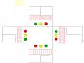
Operating principle of Gaslift:
High pressure gas from the annular space through the gaslift starting valve (installed in the Mandrel) enters the production pipe to lift the product to the surface. Normally, each well is equipped with 5 to 6 gaslift valves depending on the well structure. According to the design, when the well starting process is finished, the gaslift valves automatically close, only the last valve is opened regularly, called the working valve, to save compressed air energy and stabilize the working process of the production well.
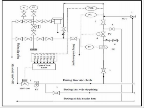
Figure I.2. 2 Gaslift operating principle diagram
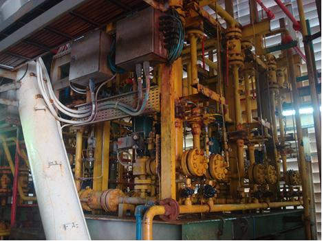
Figure I.2. 3 Gaslift system on the rig
2.3. Wellhead system and exploitation pine
2.3.1. Wellhead system
- The wellhead system has 2 main functions: hanging casing levels, installing exploitation pine trees. The wellheads at the MSP-8 rig usually hang 3 casing levels (6”x9”, 9”x12”, 12”x16”).
- Each wellhead is equipped with a pressure gauge and discharge valves. Each casing level has a pressure gauge for the annular space between the well wall and the casing, and between casing levels. This pressure value must always be monitored during the exploitation process, especially for wells with a lot of gas. The annular space pressure indicates the quality of the well's cementing. If the quality of the cementing is good, this value is close to 0. A large value means that the quality of the sealing ring is not good and thus there is gas intrusion into the gap of the cement layer and gradually destroys the structure. This is very dangerous because it can cause eruptions and explosions. Not only that, it also makes the cement layers between casing levels not tight, other fluids enter the well, causing the well to operate unstably. The casing column will be corroded or distorted. If the casing is damaged, it cannot be replaced, so the well must be destroyed, which reduces the life of the well. In case of high pressure, the fluid in the annular space is discharged through the discharge valve along the pipe connecting to the tank. In serious cases, the exploitation must be stopped and the pump must be re-filled.
- At the top casing level, there is a well-cutting line and a reverse circulation line, these two lines are designed symmetrically to each other. The well-cutting line is used when there is a temporary incident that requires stopping exploitation. The well-cutting line is used for the purpose of washing the well or exploitation.
- At the top of the wellhead pressure gauge is mounted, right below is a valve, this valve is used to cut off the pressure when the pressure gauge needs to be replaced or repaired.
- On the top branch of the exploited pine tree there is a small hole to insert a thermometer.
enter and measure the temperature at the wellhead.
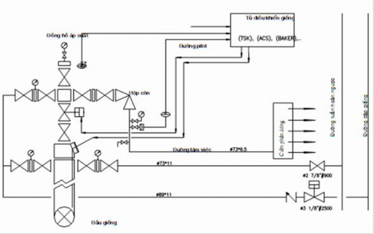
Figure I.2. 4 Wellhead system and exploitation pine
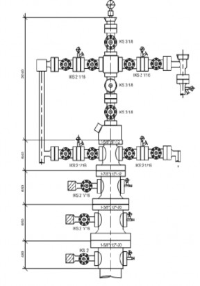
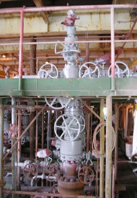
Figure I.2. 5 Diagram of exploited pine trees Figure I.2. 6 Pine trees on the trellis
2.3.2. Sub-cluster
- This is a device placed near the wellhead and the exploitation pine. Its main function is to divide the flow into technological pipelines.
- The product is extracted from the pine tree through the working line leading to the Manifold. The working line connects to the Manifold through a safety valve. When the fluid flow pressure exceeds the allowable value, the safety valve will explode, allowing the fluid to pass through it to the discharge valve. Each manifold has two safety valves, one working and one standby.
- Manifold cluster connects to five main technological pipelines: measuring tank pipeline, main working pipeline, backup working pipeline, and calling tank pipeline.
line and discharge to the tank.
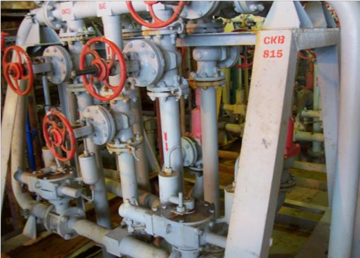
Figure I.2. 7 Manifold cluster on the rig
- In case the product line pressure is within the allowable limit (safety valve does not explode), the product line will be divided into two pipelines: the main working line and the backup working line to tank C1. From the main working line, it is divided into two lines connecting to the ball valve. The first line goes to the measuring tank, the second line is branched into four lines: the line to the tank calling the flow, the line to the storage tank,
separator return line and forward circulation line.
- Each pipe from the Manifold cluster has one to two valves to open and close the fluid flow. When it is necessary to use a certain function of the technological pipes, we will open the valve for the product flow into that pipe, the other valves will be closed depending on the requirements. For example, to measure the flow of oil and gas from the well, we will close all the valves, only open the valve leading oil to the measuring tank. The stop valves installed on the Manifold system are mostly controlled manually.
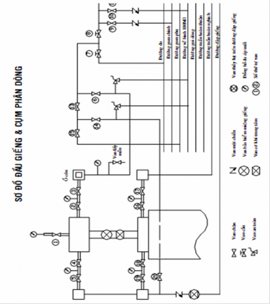
Figure I.2. 8 Wellhead and diversion cluster diagram