can be changed depending on the change in the Samples per frame (parameters) parameter when I choose the output parameter as frame-based (frame-based outputs)
Cyclic Redundancy Code Generator (CRC):
The function generates cyclic redundancy check bits and appends the length of the bits to the end of the input data frame. The CRC bits are generated according to the coding polynomials and then appended to the input data frame. After assigning the CRC bits it gives the output of the frame, the coding polynomial can be a binary vector like [1 1 0 1] or a decreasing order polynomial like [ 3 2 0] the number of output bits of the encoder depends on the coding polynomial and the number of checksums per frame in the checksums per frame parameter.
Block insert bit 0:

This block is responsible for inserting a 0 bit into the data frame in a certain direction corresponding to the direction of the input signal. Inserting a 0 bit is to coordinate the speed in the encoders.
Convolutional Encoder
This block is used to encode data and prevent errors, the input data is kept in the buffer, the output is the combination of the input data in the buffer. The encoding is carried out continuously according to the shift steps of the input data stream. This encoding block has the parameters of the coding rate (r) and the degree of the coding polynomial.
Repeat block
This block performs the function of repeating the symbols of the input frame at a given data rate. This block repeats the low rate data frames to form a higher rate to coordinate the rates in the encoders during transmission.
Puncture
This block creates an interleaving vector of the input data frame, depending on the input data frame, this block can reduce the number of input bits of the frame when we choose the interleaving vector to be different from 1. If the interleaving vector is [1], the output frame is kept intact. If the interleaving vector is different from 1 and equal to the input frame, then at the position of the element 0 in the interleaving vector, the output will remove that element.
GMSK modulator
This block modulates the input binary signal into an output signal with the parameters in the modulator being BT, which represents the bandwidth being increased over time. This parameter reduces the bandwidth used but the noise between symbols increases, the number of samples per symbol increases the output data rate by that many times.
Gaussian white noise channel (AWGN channel)
This block adds white noise to the input signal. The input is a basic frame and this block adds one frame of gauss noise to each frame. The channel parameter can change the channel properties by changing the ratio E b /N 0 (bit energy to noise power during transmission) on the channel.
GMSK demodulator
This block performs demodulation of the modulated input signal before transmission on the channel, the parameters of the demodulator match the input signal modulator and the output signal delay is shown in the delay parameter traceback length.
Blocks of interleaving, de-iterating, convolutional decoding, etc.
Performs the opposite functions of modulators and encoders before transmission over the channel. Performs error detection and correction functions during transmission over the channel.
Pass counter
Performs comparison of input data before transmission and input data when received, counting error when transmitting over a modulated channel and demodulating when receiving a signal. This unit performs comparison of input bits with received bits when transmitting over the channel with a suitable delay parameter when transmitting over the channel.
Error display
This block displays and calculates the number of errors received when transmitting over the channel, this block tells us what the error probability is.
4.2. Some results are obtained when transmitting over the transmission channel
Some error measurement results when transmitting 1e6 bits with a data frame of 172 bits (corresponding to 5814 frames) encoded with CRC 12 and 1 frame check bit with 8 zero bits inserted and convolutional code rate of ½ with repetition block of 1 and interleaving vector of 1 and EbNo ratio of transmission channel is varied and GMSK modulator with number of samples per symbol is 8 samples with the result of changing EbNo ratio on transmission channel gives us the probability of output error through different transmission channel.
Table 4 – 1: Some results given
EbNo ratio on AWGN channel (dB)
Error frame number | % frame error | |
-2 | 99 | 1,703 |
0 | 20 | 0.344 |
2 | 0 | 0 |
4 | 0 | 0 |
Maybe you are interested!
-

 Situation of Information Technology Application in Enterprises
 -
 Information Technology and Information Technology Applications
 -
 Solutions to promote the application of information technology in the tax industry in Vietnam - 30
 -
 Managing information technology projects at the Department of Customs Information and Statistics - 11
 -
 Learn about HSDPA technology and its application to 3rd - 6th generation mobile networks

We see that with the above experimental results, the EbNo ratio is inversely proportional to the number of output frame errors. The larger the EbNo ratio, the smaller the number of output errors because the output bit energy is larger than the input gauss noise, so the number of error bits decreases, leading to the number of error frames decreasing and decreasing very quickly.
CONCLUSION AND SUGGESTIONS
This thesis presents a structural model and protocols of GSM and GPRS networks, some solutions for upgrading to GPRS networks and some results obtained during data transmission. Some main points can be summarized as follows.
GSM is a 2nd generation mobile network structure that has existed for more than 10 years in Vietnam. Up to now, it has been upgraded and maintained many times but has not been able to meet the increasing demand for high-speed data transmission of users. Because GSM network has some of the following characteristics:
User traffic channels are always occupied when no data is transmitted during a conversation, wasting radio resources.
Supports low data rates, fixed to one user transmitting and receiving data only on one time slot…
GPRS is an important step towards 3rd generation cellular networks and mobile Internet. It is a packet-switched transmission technology that enables simplified wireless access to IP and X.25 networks.
GPRS has the following characteristics:
Support QoS, service priority: Depending on the subscriber's registration requirements, priority can be given to calls or data transmission when a large number of users access the network.
Multi-slot support for users, then data access speed is increased...
Some GPRS network structures differ from GSM in order to support mobile packet switching and connectivity to external packet data networks…
Next, some solutions to advance to GPRS from GSM and some results when transmitting over channels with different data rates are presented.
GPRS is a step forward to the 3rd generation mobile information network, it is the initial change in network structure and network access control, a new step to packet switching technology to support higher speed Internet access and more efficient use of radio resources as well as more support for users.
ACKNOWLEDGEMENTS
During the years of studying and researching at the Faculty of Technology, now the UNIVERSITY OF TECHNOLOGY - VNU, I have learned the most basic knowledge about the fields that the school has trained. This year is the year of finishing my graduation thesis, I have tried my best to complete my thesis well to be worthy of the teachers in the school who have taught me over the past few years. I would like to take this opportunity to express my sincere thanks to all the teachers who taught me when I was still in school, the brothers and sisters in the faculty who have enthusiastically helped and guided me. Thank you, the University of Technology, for creating conditions for me to study well and achieve the results I have today.
I would like to express my special thanks to Professor Nguyen Viet Kinh. He has guided and helped me a lot while I was doing this thesis. He gave me valuable advice so that I could continue what I wanted to pursue. He also gave me advice on future directions that I really appreciated.
The success of this thesis cannot be fully attributed to the help of teachers, fellow graduate students in the school, my family and friends who have helped, guided and encouraged me a lot while doing this thesis.
Hanoi, June 6, 2005
Pham Van Ngoc
APPENDIX
LIST OF TABLES
Table 2 – 1: Number of timeslots used in GPRS types 26
Table 2 – 2: List of three data reliability classes 38
Table 2 – 3: Late classes 39
Table 2 – 4: Logical channels in GPRS 43
Table 2 – 5: Properties of logical channels in GPRS 46
Table 2 – 6: Channel coding for traffic channels in GPRS 48
Table 4 – 1: Some results given 71
LIST OF IMAGES
Figure 1 – 1: GSM system overview 5
Figure 1 – 2: BSS 8 external interfaces
Figure 1 - 4: Small ring or chain configuration 9
Figure 1 - 5: Interface between network elements 14
Figure 1 - 6: Call to MS 19
Figure 1 – 7 illustrates the handover process between two cells belonging to the same switchboard 20
Figure 1 - 8: Call handover between BSCs 21
Figure 1 - 9: Call handover between two MSCs 22
Figure 2 – 1: Number of TS used in GPRS 25
Figure 2 – 2: GPRS network system structure 27
Figure 2 – 3: GPRS system structure and routing example 28
Figure 2 - 4: Interfaces in GPRS network 35
Figure 2 - 5: Protocol structure in GPRS transmission diagram 37
Figure 2 – 6: Uplink channel allocation 44
Figure 2 – 7: Packet Transmission Procedure to MS 45
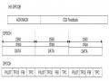
Figure 2 – 8: Multiframe structure with 52 TDMA frames 47
Figure 2 – 9: Physical layer at the air interface, code combining, interleaving and burst formatting 48
Figure 2 – 10: Encoding of GPRS data blocks 49
Figure 2 – 11: Convolutional code principle 49
Figure 2 - 12: State diagram of MS in GPRS 50
Figure 2 – 13: Routing area update procedure within SGSN 52
Figure 2 – 14: Routing area network entry procedure between SGSNs 54
Figure 2 – 15: Description of the network entry procedure from MS 56
Figure 2 – 16: Procedure to leave GPRS network from mobile station 57
Figure 2 – 17: Procedure to leave GPRS network from HLR 58
Figure 2 – 18: Data rates with GPRS encoding methods 60
Figure 3 – 1: Mobifone 63 GPRS network structure
Figure 4 – 1: functional block diagram when transmitting data 67