The last-mile DCH timing is not tied to the HS-SCCH (or HS-DSCH) timing.
3.1.3 High-speed dedicated physical control channel (HS-DPCCH)
The uplink channel must carry both ACK/NACK information for physical layer retransmissions and quality feedback information used in the Node B scheduler to determine which device is to transmit and at what data rate. It is required to ensure soft handover operation in case not all Node Bs support HSDPA. Therefore, it has been left in the uplink channel structure and the necessary new information elements added on a parallel code channel HS-DPCCH. HS-DPCCH is divided into two parts, shown in Figure 3.3, and carries the following information:
• ACK/NACK transmission, reflecting the result of the CRC check after packet demodulation and reassembly.
• The downlink channel quality indicator (CQI) indicates the transport block size, modulation type, and number of parallel codes that can be received correctly (with a reasonable block error rate (BLER)) on the downlink.
Maybe you are interested!
-
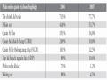
 Situation of Information Technology Application in Enterprises
 -
 Mobile TV using DVB-H - 6 technology
 -
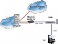 Learn about IPTV technology and implementation solutions at VNPT Bac Ninh - 9
 -
 Solutions to promote the application of information technology in the tax industry in Vietnam - 30
 -
 Strengthening the application of information technology to improve the competitiveness of small and medium enterprises in Vietnam - 1
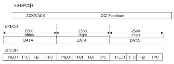
Figure 3.3: HS-DPCCH structure
In the 3GPP standard, there has been a lively discussion on this aspect, as it is not a trivial matter to define a feedback method that will take into account different receivers and so on, and at the same time easily switch scheduler information at the Node B. In other cases, the feedback consists of 5 bits carrying quality-related information. One signal state is reserved for the 'don't bother transmitting' state and the others represent which terminals are available to receive at the moment. Thus, the range of
The quality state from transmitting a QPSK code up to 15 16QAM codes (including different coding rates). Obviously, the terminal capability needs to be added to the feedback signal; therefore, terminals that do not support a certain number of codes of the CQI feedback table then the value of the signal for the power reduction factor is related to the most supported combination from the CQI table. The CQI table includes the range of transmission block size, number of codes and modulation combinations also defined the resulting coding rate. HS-DPCCH requires some uplink transmission power, which affects the uplink link cost.
3.2 HSDPA PHYSICAL LAYER OPERATION PROCEDURE
The operation of the HSDPA physical layer follows these steps:
• The scheduler at the Node B evaluates the differences in channel conditions between users in the network, how much data is waiting in the buffer for each, how much time has passed since a particular user was served, which users are waiting for retransmissions... The exact criteria that must be taken into account at the scheduler is a matter for the provider to implement.
• Once a terminal has been identified to be served in a particular TTI, the Node B determines the necessary HS-DSCH parameters. For example, how many codes can or can be filled? Can 16QAM be used? What are the terminal capability constraints? The terminal soft memory capabilities also define which HARQ types can be used.
• Node B starts transmitting two HS-SCCH slots before the corresponding HS-DSCH TTI to indicate the necessary terminal parameters. The selection of HS-SCCH (from a maximum set of four channels) is free when there is no data for the terminal from the previous HS-DSCH frame.
• The terminal monitors the HS-SCCHs presented by the network and once the terminal decodes part one from an HS-SCCH destined for it, it will start decoding the rest of the HS-SCCH and will buffer the necessary codes from the HS-DSCH.
• Once the decoded HS-SCCH parameters from the second part are available, the terminal can determine which ARQ process it is in and whether it needs to be combined with data already in the soft buffer.
• After decoding the potentially combined data, the terminal sends on the uplink an ACK/NACK indication, depending on the output a CRC check is performed on the HS-DSCH data.
• If the network continues to transmit data to the same terminal in subsequent TTIs, the terminal remains on the same HS-SCCH that was used in the previous TTI.
The HSDPA operating procedure precisely determines the timing values for terminal operations from reception of the HS-SCCH through decoding of the uplink ACK/NACK signal. The terminal timing key value is 7.5 slots from the end of the HS-DSCH TTI to the start of the ACK/NACK transmission on the uplink HS-DPCCH. The timing relationship between the downlink and uplink is illustrated in Figure 3.4. The network side is asynchronous in terms of sending a retransmission in the downlink. Therefore, depending on the implementation, different time periods may be allocated for the scheduling process on the network side.
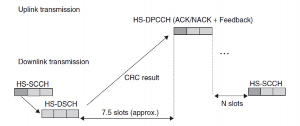
Figure 3.4: Terminal time for HARQ process
The terminal capabilities do not affect the duration of a time slot transmission but decide how long a slot can be transmitted to the terminal. The capabilities include information about the minimum inter-TTI interval whether the next TTI can be used or not. A value of 1 indicates that the next TTI can be used, while values 2 and 3 respectively indicate that there is at least one or two empty TTIs between transmitted packets.
Since the downlink DCH and uplink DCH do not have an alignment slot for HSDPA to transmit channels, the uplink HS-DPCCH can start in the middle of the uplink slot as well, and this needs to be taken into account during the uplink power setting process.
The uplink space is quantized to 256 chips (symbol adjusted) and the minimum value is 7.5 slots -128 chips to 7.5 slots 128 chips. This is illustrated in Figure 3.5.
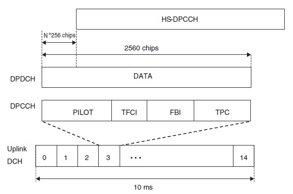
Figure 3.5: DPCH and HS-SCCH timing relationship
CHAPTER 4: APPLICATIONS ON HSDPA
4.1 FULL-DUPLER VOIP AND CHAT ENHANCEMENT
Compared to many other applications running over IP, the throughput requirements for full-duplex VoIP are low, up to a few tens of Kbps, but the underlying requirements are much higher, so again, RTT – and not the connection throughput – is the factor that limits the end user service and network capacity. The ITU recommendation for single-path transmission time for full-duplex voice states that users are satisfied with a mouth-to-ear delay of about 280ms. With delays greater than 280ms, the interaction of the voice connection deteriorates rapidly. And when delays reach 400ms, the voice is not satisfied with the connection interaction. Note that the delay referred to here is the mouth-to-ear delay, and therefore includes not only the transmission delay but also the processing (encoding/decoding) delay in the transmitter and receiver. The ITU recommendations also include guidelines for encoding/decoding latency. For most mobile samplers, latency requirements range from 50ms to 100ms. Ignoring processing delays, the delay from transmission to termination is less than 200ms. When we compare this latency requirement with the RTT of less than 200ms in WCDMA and less than 100ms in HSPA, it is clear that VOIP performs well in both technologies. With the shorter RTT in the HSPA radio link, the allowable latency in HSPA is greater than in WCDMA. Note that as the load in HSPA increases, the RTT also increases.
For applications that require conversation, the required mouth-to-ear latency is less demanding than full-duplex VOIP. On the other hand, these applications place strict requirements on the timing of the radio connection. This is because every time a user requests to talk, the system must establish a radio connection, and the time it takes to do this directly affects the user's connection to the conversation.
4.2 REAL-TIME GAMES
There are many groups of network games, and these groups have different requirements on the mobile network, which depend on the time to establish a radio connection and the battery life. Below are examples of game groups
• Real-time action games.
• Real-time strategy games.
• Strategy games on a spinning platform.
The most demanding are real-time games. While the maximum bitrate of such games rarely exceeds 100-200 kbps and the average bitrate is usually around 10-30 kbps. RTT requires a typical latency of 125-250ms for the most demanding games. Therefore, HSPA will be able to support background play with performance loading as long as the end-user network is well controlled. The data rate requirements for real-time games change very rapidly. HSPA has an advantage over Release 99 in that the data rate can be met immediately.
4.3 TV STREAM - MOBILE
Providing a good quality video stream to a mobile screen using the latest video sampling requires rates of 32 to 128 kbps depending on the content. Most types of content carry 64 kbps of quality which will be good enough. WCDMA networks can provide 64-128kbps with very good quality. However, what HSPA brings is more capacity, which in turn enables the market to deliver high bit rates to end users.
Pre-3G wireless networks only achieved data rates of 50-200 kbps, while 3G networks with HSDPA capabilities can provide data rates of up to 1 Mbps. Therefore, streaming applications must adapt the media rate. Stream media rate adaptation is already supported in some terminals, while full support for the 3GPP standardized media rate adaptation scheme is included in 3GPP Release 6. To select the appropriate media rate the streaming server needs to know:
- What type of mobile station is it aimed at. In the case of a terminal with limited bit rate capabilities, the media rate needs to take those limitations into account.
- What initial media speed needs to be used may be in a 2G network, and sometimes it may be in a 3G network
- When to increase or decrease media speed.
In practice, the mobile station and the server exchange information about their capabilities before the flow starts. How this works is explained in step 1.
The initial media rate selection is more difficult. In today's networks it is based on the telephone network model. When the bit rates of the service solutions are set in the terminals and WCDMA and HSPA networks then the bit rates can be used to guide the initial media rate selection.
4.4 EMAIL
Latency values in HSPA networks are usually low enough for email applications. Even if the user does not download attachments or send emails, the email application used to send messages to the mobile phone:
- The subject line and first few KB of each received email are pushed to the terminal.
- Keep active messages exchanged between server and terminal. The size of the kept messages is very small.
Figure 4.1 gives an estimate of the power consumption of a mobile phone on messages retained every 4 minutes and receiving 0–50 email messages per hour.
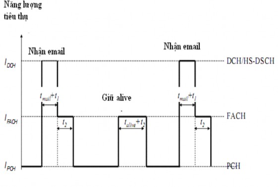
Figure 4.1: Estimated power consumption of mobile phones
The keep active messages are carried on the RACH/FACH channels while parts of the messages - of a few KB - are carried on the HS-DSCH.
The power consumption is shown in Figure 4.1. The power consumption depends on the number of messages received and the parameters set on the radio network. If we assume 5-sec DCH clocks and FACH 50 messages per hour, the standard mobile device of 53h will use 1000mAp of battery power. This calculation proves that the parameters in the email push application are good in the radio network.
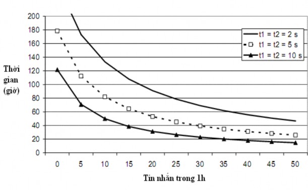
Figure 4.2: Accessing email from mobile using 1000-mAh battery
If the PCH state is not used by the network, the UE is moved from the FACH to the idle state and the RRC connection is released. When data arrives in the downlink from the 3G core, the RRC connection needs to be occupied. The RRC connection setup procedures can increase terminal power consumption and reduce battery standby time. Using the PCH state is beneficial to achieve long standby time.