The quality of biogas depends on the source of production and the time the organic matter exists in the biogas digester. Biogas usually contains 60-70% CH 4 , 30-40% CO 2 and less than 1% H 2 S (usually in the range of 100 to 2000ppm). Other gases such as N 2 can be up to 10%, H 2 can be up to 5%.
Figure 1.5 shows the kinetics of biogas from organic waste. Initially, the gas production rate increases rapidly and reaches a maximum value in the range of 5-7 days. Then the gas production rate decreases. The amount of gas produced remains almost constant after 25 days of storing the raw material in the pit.
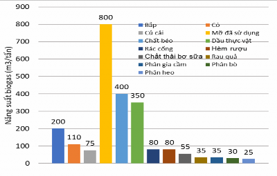
The biogas production capacity of different materials is shown in Figure 1.6. The results show that the gas production capacity of fats is much higher than that of other materials, followed by corn, grass, sewer waste, and beer dregs. Livestock and poultry manure, rice husks, and straw have lower gas production capacity, but these are abundant sources of raw materials in agricultural production in our country.
Maybe you are interested!
-

 Ensuring Raw Materials for Production in the Enterprise:
 -
 Completing the accounting of raw materials at Son Thuy Production and Trading Joint Stock Company - 1
 -
 Completing the accounting of raw materials for yarn production at Ha Nam Textile Company - 9
 -
 Completing the accounting of raw materials at Thai Hoa Production and Trading Company Limited - 2
 -
 Completing the management and supply of raw materials at the training equipment manufacturing factory X55 - 7
Figure 1.6: Biogas production capacity of some raw materials [1]
1.2.2.2. Impurities in biogas
- Hydrogen sulphide H 2 S
Hydrogen sulphide (H 2 S) is a colorless, highly toxic, flammable gas. H 2 S has a "rotten eggs" odor. Its odor can be detected at low concentrations (0.05-500 ppm). H 2 S dissolves in water to form a weak acid. When burned, H 2 S produces SO 2 , a highly corrosive substance (sulphuric acid) and pollutes the environment.
(acid rain). H 2 S is a very toxic substance (equivalent to hydrogen cyanide) with a low toxic limit (about 10 ppm H 2 S). When the H 2 S content in the air reaches 1.2-2.8 mg/l or 0.1%, it causes immediate death. When this content reaches 0.6 mg/l or 0.05%, it can cause death within 30 minutes to 1 hour.
Plant materials generate little H 2 S in biogas. Poultry manure generates on average up to 0.5 % by volume H 2 S, cattle and pig manure about 0.3 % by volume H 2 S. Protein-rich wastes (e.g. wine must, molasses ...) can generate large amounts of H 2 S (up to 3 % by volume) in biogas. Inorganic sulphates also generate significant H 2 S.
The harmful effects of H2S on biogas production and use can be summarized as follows:
In the biogas digester, dissolved H2S is contained in the fermentation sludge and is in equilibrium between dissolved H2S and gaseous H2S . High concentrations of dissolved H2S can kill bacteria in the sludge, inhibiting the biogas production process and causing changes in biogas composition. In this case, it is necessary to supply less sulfur-rich materials to the digester and dilute the materials with water. In less serious cases, it is only necessary to stir the materials in the digester vigorously to separate H2S from the sludge.
During use, the presence of H2S gas in biogas causes corrosion of metal parts. Iron is the subject of surface attack, although not a major corrosion. Galvanized parts also suffer similar surface corrosion. Details made of non-ferrous metals, such as pressure regulators, gas flow meters, valves and brackets, etc. are much more seriously affected. These materials corrode very quickly.
The product of the combustion of H 2 S is SO 2 which, when combined with water vapor , produces acid, which corrodes engine parts in the combustion chamber, exhaust system and various exhaust gas contact parts. The damage is more serious when the engine is started frequently, the operating time is short and the temperature is relatively low when starting and after stopping the engine. The first overhaul time can be reduced by about 10-15% for engines using biogas containing H 2 S compared to engines running on liquid fuel. On the other hand, when using biogas containing sulfur as fuel, the time between
The interval between two engine oil changes is also shortened. Due to SO 2 in the combustion products and water vapor dissolved in the lubricating oil, the oil becomes acidic and degrades, losing its lubricating ability and sometimes corroding metal parts. Under the condition of continuous operation of the engine using biogas fuel containing sulfur, the interval between two oil changes is reduced by 200-250 hours compared to when operating with fuel containing no sulfur.
- Carbonic
Carbonic acid is the main impurity present in biogas. It is non-toxic but it reduces the calorific value of the fuel. To increase the energy value of biogas per unit volume of storage, especially when compressing biogas to fuel transport equipment, carbonic acid must be filtered out. In cases where biogas is used as a fuel on site (such as cooking, running stationary engines, etc.), CO2 filtering is not necessary .
1.2.2.3. Filtering impurities in biogas
a. Requirements for biogas filtration in actual use
In principle, we can completely filter out impurities in biogas to get pure methane. Of course, the filtering process is expensive, so depending on the specific requirements of the biogas equipment, people filter out impurities at different levels. Figure 1.7 introduces the requirements for filtering impurities in biogas in practice when using this fuel to produce electricity with different solutions.

Figure 1.7: Requirements for filtering impurities in biogas with different power generation solutions [1]
b. Carbonic filtration
CO 2 is the second gas with the largest proportion in biogas. CO 2 and CH 4 usually account for 95% to 99% of biogas volume. The heat content per unit volume of biogas can be increased quite significantly if CO 2 is removed from the fuel. For example, biogas containing 55% CH 4 and 45% CO 2 , if CO 2 is completely removed , the heat content per unit volume of the gas increases up to 1.8 times compared to the original raw fuel.
Removal of CO 2 is also required when storing biogas to reduce the volume of the storage device. The presence of CO 2 in biogas significantly affects the use of this fuel in internal combustion engines. The volume of biogas containing 50% CH 4 must be 3.7 times the volume of fuel containing 100% CH 4 to ensure the same engine power.
However, for many uses and in most small capacity systems, CO 2 removal may not be necessary.
CO 2 in biogas can be removed by passing the gas through water containing any alkali, such as calcium hydroxide Ca(OH) 2 . CO 2 can also be removed by compression. The condensation pressure of CO 2 is much lower than that of CH 4 at the same temperature. Therefore, before compressing the biogas into a high-pressure tank, the biogas can be passed through a CO 2 compression condensation stage at suitable temperature and pressure conditions. The liquid CO 2 is then recovered for other uses. This process does not require chemicals but is only suitable for large-scale industrial biogas stations.
c. Filter H 2 S
H 2 S can be filtered by absorption on an alkaline substance such as Na 2 CO 3 or NaOH. H 2 S can also be filtered with water because it is more soluble in water than methane. This process is purely physical absorption. H 2 S can be dissolved in water at a rate of 2.6 volumes of gas in 1 volume of water at 20 C. When the gas flow is run in the opposite direction to the water flow and shaken vigorously, the process of dissolving H 2 S into water is easier . The advantage of this method is that it does not use chemicals but can still filter CO 2 and H 2 S at the same time . The disadvantage is that a large amount of water must be used even when regenerating water as well as limiting the filtration of H 2 S because CO 2 reduces the pH of the solution.
For large biogas plants, H2S can be removed by using a microbial catalyst method . This method involves injecting a small amount of air (about 2-8%) into the biogas. The oxygen in the air acts as a bio-catalytic agent, separating the sulfur from the sludge surface. This simple method works well when biogas is stored on the sludge surface because the bacteria need moisture, temperature (optimally about 35-37 C) and nutrients. The bio-catalytic method can also be carried out outside the biogas plant in desulfurization columns. This method facilitates the control of the desulfurization process and the precise adjustment of the amount of oxygen added. The reactor is similar to a filter, consisting of a space containing a porous material (plastic or similar) in which the microorganisms can grow, a water chamber, a pump and a showerhead that sprays evenly over the space containing the porous medium. H2S is oxidized by biological processes into acid products or free sulfur by injecting a small amount of air. The showerhead washes away the acid products and provides nutrients for microorganisms. Therefore, the water contained in the tank must be highly alkaline and rich in nutrients for microorganisms.
For small-volume biogas plants, H2S removal by adsorption is often used. Sulfur in gaseous fuels can be removed using quicklime, solid slaked lime or liquid slaked lime. However, this process is no longer used in large-scale biogas plants because the large amount of odorous waste generated from this process cannot be adequately treated. The treatment of large amounts of dissolved or suspended slaked lime from the desulfurization process requires complex equipment.
The most common method of removing H 2 S from biogas is to pass it through a filter containing rust. One of the molecules found in rust is ferric oxide Fe 2 O 3 . When it reacts with H 2 S, the product is ferric sulfide (Fe 2 S 3 ). Rarely, the reaction produces ferrous sulfide (FeS) or sulfur (S). Both ferric sulfide and ferrous sulfide are very unstable. In the presence of oxygen they are converted to Fe 2 O 3 and generate heat, so care must be taken when exposing these sulfides to air . After a period of filtration, the filter element needs to be regenerated by slowly passing a small amount of air through the filter.
Filter media using this solution are made by mixing cast iron powder, low carbon steel powder or turnings with damp sawdust or ground corn cob, or any other damp, porous material. Typically, about 1.5 to 2 kg of iron per litre of substrate is used. It is best to use cast iron or low carbon steel as these rust better than other alloys. If the filter mixture is kept moist for 3 to 4 weeks, the H 2 S filtering effect will be better. To speed up the rusting process, we can add salt to the water to moisten the material, but this process will generate more heat.
1.3. Biogas engine [1]
1.3.1. Spark ignition biogas engine converted from gasoline engine
Converting a conventional spark ignition engine to use gas fuel is relatively easy because it is designed to operate with a fuel/air mixture and ignited by an electric spark. The basic conversion is to replace the carburetor with a gas-fuel mixture generator. Control of engine power and speed is achieved by varying the amount of mixture supplied, that is, adjusting the throttle position as in the case of a gasoline engine. Adjusting the ignition timing (since the combustion rate of biogas is lower than that of gasoline) is not difficult because the ignition system allows for a wide range of ignition timing changes.
Increasing the engine compression ratio is also necessary to increase the engine efficiency and power. However, after changing the compression ratio, the engine cannot use gasoline again when the biogas supply runs out.
Converting a gasoline engine to a biogas engine mainly affects the following factors:
- Carburetor;
- Gap between spark plug poles;
- Advance ignition angle;
- Maintenance.
When renovating the carburetor, we must pay attention to the air-fuel ratio to ensure the most optimal engine performance. The air-fuel ratio for complete combustion of biogas containing 60% methane is 6.03:1. The minimum content of methane in
Biogas used in 4-stroke engines is 35%. On the other hand, the mixture of methane and carbon dioxide cannot be burned if the volume of carbon dioxide is 3 times larger than the volume of methane. The optimal compression ratio for biogas engines is in the range of 11-16. However, most industrial engines using natural gas have compression ratios in the range of 7-10.
Biogas has a lower flame velocity than other gaseous fuels. Therefore, the ignition advance angle must be increased to ensure perfect combustion and improve engine performance. The optimal ignition advance angle of a 25kW engine running on biogas containing 60% methane is between 33 and 45 before TDC [1]. For a 55kW engine using similar biogas, the optimal ignition advance angle is 45 before TDC [1].
Biogas engines converted from gasoline engines produce less power when running on gasoline. The reason is that gaseous fuel occupies a larger volume in the mixture generator than liquid fuel. On the other hand, the volumetric calorific value of liquid fuel is larger than that of gaseous fuel and it cools the mixture when it evaporates, thus increasing the amount of air intake into the engine.
For engines running on biogas, because the fuel contains CO 2 , the amount of fuel/air mixture fed into the engine is also reduced. Because the spark ignition engine always keeps the excess air coefficient λ = 1 ± 0.1 and the engine intake system has been designed to run on gasoline, the total energy of the biogas/air mixture fed into the engine is smaller than when it runs on gasoline. Due to the decrease in fuel energy that can be brought in, the engine power also decreases at a similar rate. The level of power reduction depends on the volumetric heating value of the gaseous fuel, for example, biogas containing 70% CH 4 has a higher volumetric heating value than biogas containing only 50% CH 4 . When the engine runs on lean biogas containing 60% CH 4 , the volumetric heating value of the fuel Q LHV = 25,000 kJ/nm³ , the level of engine power reduction is about 20% compared to when running on gasoline. The corresponding reduction in engine power when running on refined methane or natural gas is 10%, and when running on LPG is 5%. This reduction in power should be considered when selecting an engine to be modified to match the capacity of the working machine.
Regardless of the level of completion of the above engine modifications, the
The reduction in engine power when switching to biogas depends on the methane content of the fuel. When the engine runs on biogas containing 60% methane, the engine power is reduced by 15-20% compared to when running on gasoline. Similarly, when switching from natural gas to biogas, the power is reduced by about 5-20% compared to when running on natural gas [1].
1.3.2. Spark ignition biogas engine converted from diesel engine
When converting a diesel engine into a spark ignition biogas engine, some parts of the engine must be changed. The main changes are:
1. Remove the high pressure pump assembly and nozzle;
2. Reduce the compression ratio to ε = 10-12;
3. Install ignition system;
4. Install a mixture generator to ensure the air/fuel ratio remains constant.
Removing the injection system is the easiest part. Usually the high pressure pump drive system is reused to drive the distributor. If this mechanism is not needed again, the vent in the engine block must be sealed to prevent dirt from entering the crankcase and to avoid loss of lubricating oil.
The reduction of the compression ratio to ε = 12 or lower is mainly due to the fact that the spark does not work effectively at high pressure. On the other hand, the selection of a reasonable compression ratio of the engine also depends on the anti-knock properties of the gas fuel. Normally, the compression ratio of a spark ignition engine in industry is in the range of ε
=10.5-11.5 to be able to use many different types of gas fuels.
The change in compression ratio is achieved by increasing the combustion chamber volume V c .
This can be done using the following solutions:
1. Replace the original piston with a new piston so that the compression ratio is lower;
2. Replace the original cylinder head with a new cylinder head with a lower compression ratio;
3. Cut off the piston top material;
4. Machining to expand the combustion chamber in the cylinder head;
5. Use thicker lid gasket.