3.2.2 Program
Send trigger signal
Program sequence:
Robot
Vision
Trigger task sequence
Trigger camera
Run toolblock
Processing of received coordinates
Split string into X,Y,Z, state
Send string X,Y,T, status
Move to the received coordinates
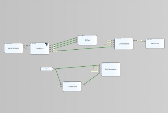
Figure 3. 6 block sequences of Cognex Designer
Blocks:
Block one: Cam_Acquire : Allows setting input image
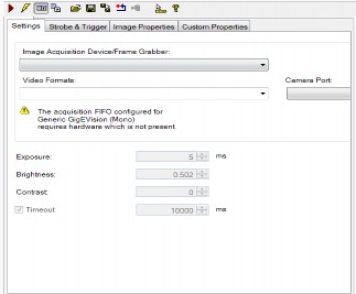
Figure 3. 7 Block Cam_Acquire
Toolblock 2: The software's image processing center, a library containing all the tools that meet the main needs of Machine Vision. In the framework of the thesis, the tool "CogPMalignTool" is used. Allows determining the X, Y, T coordinates of the object to be located, in addition, it can also be used. CogPMalignTool allows users to train the recognition area (scan area) and recognition features (mark points) from which they can recognize objects at different positions in the visible area and give the required results.
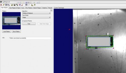
Figure 3.8 Training mark points and scan area
Block 3 Offset: Because the coordinate system of the robot and vision are different, we need to accurately transmit the coordinates for the robot to move to solve the problem as follows. First, we let the robot go to the most accurate pick-up point and put the product to be picked in that position, then take a photo and save the selected coordinates as the Master coordinates. The position of the next products is equal to the product coordinates minus the master coordinates.
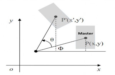
Figure 3.9 Description of offset principle
$Xoffset = ( $X- $Xmaster ) * 100 ;
$Yoffset = ( $Y-$Ymaster) * 100 ;
$Rotationoffset = -($T-$Rotationmaster )* 100 * 180 /Math.P
Block four Scriptblock1: This block performs string concatenation for Xoffset, Yoffset, Rotationoffset data and the ABB robot format status received via socket is string form. Content of string input command:
string a =
Xoffset. ToString ( "F2" ) + "," + Yofffset1. ToString ( "F2" )+ "," +Rotationoffset.
ToString ( "F2" )+ "," +trangthai. ToString (); return a;
Three blocks: Now, Scriptblock, Subsequence are responsible for creating the database.
3.3 Mitsubishi PLC Programming
Software using GX Works2 provided by Mitsubishi
Steps to follow: step 1 install parameter, step 2 install intelligent Function Module, step 3 programming.
3.3.1 Parameter settings
There are 2 main parameter groups that need to be set: PLC parameter, Network parameter.
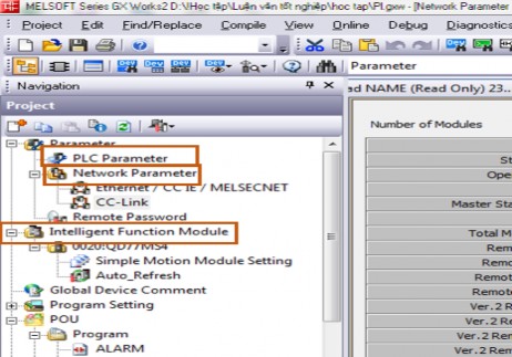
Figure 3. 10 required settings
PLC parameters
Required settings:
Built Ethernet port setting: In the installation window, you need to set parameters such as setting IP Address for PLC device, Communication data code, and you can also install additional FTP setting, Time setting...
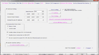
Figure 3.11 Built in Ethernet port setting window
In the I/O Assignment section: Declare devices using I/O mounted on the base. In the thesis, the QD77MS4 device is used for motor control.
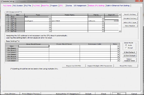
Figure 3. 12 I/O Assignment Setup Window
Program: Declare programs to be scanned for PLC to execute. In the lesson, there are 6 declared programs: ALARM, ROB_VIS, INITIAL, SER_MOTO, NAME, MAIN
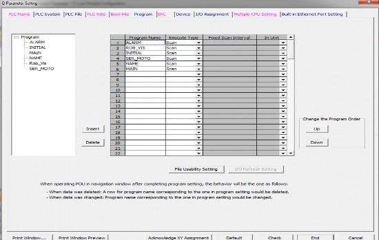
Figure 3.13 Program settings window
QJ61BT11N
CClink master
1 intelligent Station DSQ378B
1 intelligent Station DSQ378B
Robot communication

7 Remote I/O Station
Peripheral control I/O
Network Parameter: Set parameters for communication modules. In the thesis, the communication module used is CClink QJ61BT11N configured as follows:
Robot communication
4 Remote Driver Station Conveyor inverter | ||
Maybe you are interested!
-

 Study on the effectiveness of hospital wastewater treatment by anaerobic (AO) method using improved ECO - BIO - BLOCK (EBB) biological media - 10
 -
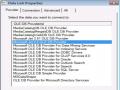 Creating a Data Environment Designer Using Data View
 -
 Study on the effectiveness of hospital wastewater treatment by anaerobic (AO) method using improved ECO - BIO - BLOCK (EBB) biological media - 2
 -
 Stress Testing At Conventional Block Foundations
Parameters to note during setup: First Start I/O No: Is the first address that the module
Second Type: Is the type of module in the system. If it is a multi-module system, there will be 1 Master and many Slaves.
Third Total Module connected: Is the total number of modules and cclink master module connected to.
Fourth Remote input(Rx) is the first X address of cclink. Fifth Remote is address(Ry) is the first Y address.
Sixth Remote Register(Rwr) : Address of the first read register.
Seventh Remote Register(Rww) : First input register address.
Eighth Station information setting: we need to declare all usage status in this section
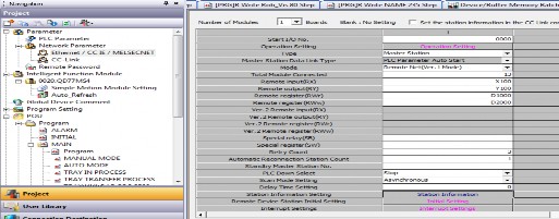
Figure 3.14 CClink configuration window
Declare station information setting:
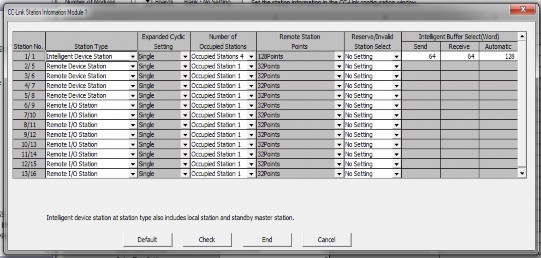
Figure 3. 15 Station information setting
3.3.2 Install Intelligent Function Module
The group sets up Mitsubishi intelligent modules such as: Analog Module, temperature module, Counter module, Motion module... In the thesis we use Motion module QD77MS4.
46
The setup window allows us to set parameters for the motor through modules such as: Speed, velocity, torque, home speed, return method, travel method...
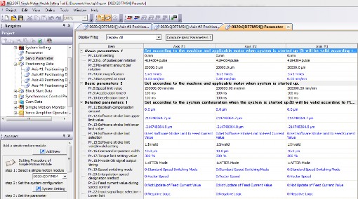
Figure 3. 16 parameter settings for QD77MS4 module
3.3.3 Programming for PLC
Program structure: The program is divided into 6 main programs: ALARM, INNITIAL, MAIN, NAME, Rob_vis, SER_MOTO
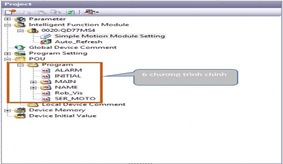
Figure 3.17 Program structure