Usually, high dispersion and large surface area are two factors that determine the catalytic ability of a material. Conducting polymers are considered as a carrier that can keep the catalyst, which is a metal or metal oxide, evenly dispersed (Figure 1.8).
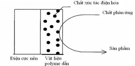
Figure 1.8. Schematic diagram of electrocatalyst dispersion in conducting polymer films The porous structure and large surface area of many conducting polymers have created
favorable conditions for the development of many new catalysts and electrocatalysts. Recent studies have shown that composites based on Ppy and nano-sized spinel oxides have shown high catalytic efficiency and stable performance in the oxygen reduction reaction to form hydrogen peroxide [110,114,115]. This is a new research direction with practical significance, especially in the field of environmental treatment and protection.
1.3.4. Application of Ppy and Ppy(oxide)/Ppy materials as catalysts in environmental treatment by electrochemical Fenton effect
Maybe you are interested!
-

 P. Results of Treatment of Organic Substances in Leachate by Perozone with the Effect of Ph in 60 Minute Reaction Time
 -
 Car body electrical practice - 8
zt2i3t4l5ee
zt2a3gs
zt2a3ge
zc2o3n4t5e6n7ts
If the voltage is out of specification, replace the wire or connector.
If the voltage is within specification, install the front fog light relay and follow step 5.
Step 5 Check the front fog light switch
- Remove the D4 connector of the fog light switch
- Use a multimeter to measure the resistance of the front fog light switch.
Measurement location
Condition
Standard
D4-3 (BFG) -D4-4 (LFG)
Light switchFront Fog OFF
>10kΩ
D4-3 (BFG) -D4-4 (LFG)
Front fog light switchON
<1 Ω
- Standard resistor
D4 connector is located on the combination switch assembly.
If the resistance is out of specification, replace the combination switch (the fog light switch is located in the combination switch).
If the resistance is within specification, follow step 6.
Step 6 Check wiring and connectors (front fog light relay-light selector switch)
- Disconnect connector D4 of the combination switch assembly
- Use a voltmeter to measure the voltage value of jack D4 on the wire side.
Measurement location
Control modecontrol
Standard
D4-3 (BFG) - (-) AQ
TAIL
11 to 14 V
D4 connector for the wiring of the combination switch assembly
If the voltage does not meet the standard, replace the wire or connector.
If the voltage is within standard, there may have been an error in the previous measurements.
Step 7 Check the front fog lights
- Remove the front fog light electrical connector.
- Supply battery voltage to the fog lamp terminals
Jack 8, B9 of front fog lamp on the electrical side
blind first.
Power supply location
Terms and Conditions
Battery positive terminal - Terminal 2Battery negative terminal - Terminal 1
Fog lightsbefore morning
- If the light does not come on, replace the bulb.
If the light is on, re-plug the jack and continue to step 8.
Step 8 Check wiring and connectors (relay and front fog lights)
- Disconnect the B8 and B9 connectors of the front fog lights.
- Use a voltmeter to measure voltage at the following locations:
Measurement location
Switch location
Terms and Conditions
B8-2 - (-) AQ
Electric lock ON TAIL size switchFog switch ON
11 to 14 V
B9-2 - (-) AQ
Electric lock ONTAIL size switch Fog switch ON
11 to 14 V
B8 and B9 connectors on the front fog lamp wiring side
Voltage is not up to standard, repair or replace the jack. If up to standard, there may have been an error in the measurement process.
2.2.4. Procedure for removing, installing and adjusting fog lights 1. Procedure for removing
- Remove the front inner ear pads
Use a screwdriver to remove the 3 screws and remove the front part of the front inner ear liner
-Remove the fog light assembly
+ Disconnect the connector.
+ Use a screwdriver to remove 3 screws to remove the fog light cover
2. Installation sequence
-Rotate the fog lamp bulb in the direction indicated by the arrow as shown in the figure and remove the fog lamp from the fog lamp assembly.
-Rotate the fog light bulb in the direction indicated by the arrow as shown in the figure and install the light into the fog light assembly.
- Use a screwdriver to install the fog light cover
-Install the electrical connector
Attention: Be careful not to damage the plastic thread on the lamp assembly.
- Install the front inner ear pads
Use a screwdriver to install the front inner bumper with 3 screws.
3. Prepare the vehicle to adjust the fog light convergence. Prepare the vehicle:
- Make sure there is no damage or deformation to the vehicle body around the fog lights.
- Add fuel to the fuel tank
- Add oil to standard level.
- Add engine coolant to standard level.
- Inflate the tire to standard pressure.
- Place spare tire, tools and jack in original design position
- Do not leave any load in the luggage compartment.
- Let a person weighing about 75 kg sit in the driver's seat.
4. Prepare to check the fog light convergence
a/ Prepare the vehicle status as follows:
- Place the car in a dark enough place to see the lines. The lines are the dividing line, below which the light from the fog lights can be seen but above which it cannot.
- Place the car perpendicular to the wall.
- Keep a distance of 7.62 m between the center of the fog lamp and the wall.
- Park the car on level ground.
- Press the car down a few times to stabilize the suspension.
Note: A distance of approximately 7.62 m is required between the vehicle (fog lamp center) and the wall to adjust the convergence correctly. If the distance of 7.62 m cannot be achieved, set the correct distance of 3 m to check and adjust the fog lamp convergence. (Since the target area varies with the distance, please follow the instructions as shown in the figure.)
b/ Prepare a piece of thick white paper about 2 m high and 4 m wide to use as a screen.
c/ Draw a vertical line through the center of the screen (line V).
d/ Set the screen as shown in the picture. Note:
- Keep the screen perpendicular to the ground.
- Align the V line on the screen with the center of the vehicle.
e/Draw the reference lines (H, V LH and V RH lines) on the screen as shown in the figure.HINT:
Mark the center of the fog lamp on the screen. If the center mark cannot be seen on the fog lamp, use the center of the fog lamp or the manufacturer's name mark on the fog lamp as the center mark.
H line (fog light height):
Draw a line across the screen so that it passes through the center mark. Line H should be at the same height as the center mark of the fog light bulb.
Line V LH, V RH (center mark position of left fog lamp LH and right fog lamp RH):
Draw two lines so that they intersect line H at the center marks.
5. Check the fog light convergence
a/ Cover the fog lamp or remove the connector of the other side fog lamp to prevent light from the unchecked fog lamp from affecting the fog lamp convergence test.
b/ Start the engine.
c/ Turn on the fog lights and make sure that the dividing line is outside the standard area as shown in the drawing.
6. Adjust the fog light convergence
Use a screwdriver to adjust the fog light to the standard area by turning the toe adjustment screw.
Note: If the screw is adjusted too far, loosen it and then tighten it again, so that the last rotation of the light adjustment screw is clockwise.
3. Self-study questions
1. Describe the operating principle of the lighting system with automatic headlight function
2. Describe the operating principle of the lighting system with the function of rotating headlights when turning
3. Draw diagram and connect lighting system on Hyundai Porter car
4. Draw diagram and connect lighting system on Honda Accord 1992
5. Draw the lighting circuit on a 1993 Toyota Lexus
LESSON 3 MAINTENANCE AND REPAIR OF SIGNAL SYSTEM
I. IMPLEMENTATION GOAL
After completing this lesson, students will be able to:
- Distinguish between types of signals on cars
- Correctly describe common symptoms and suspected areas causing damage.
- Connecting signal circuits ensures technical requirements
- Disassemble, install, check, maintain and repair the signal system to ensure technical requirements.
- Ensure safety in work and industrial hygiene
II. LESSON CONTENT
1. General description
The signal system equipped on cars aims to create signals to notify other vehicles participating in traffic about the vehicle's operating status such as: stopping, parking, braking, reversing, turning...
Signals are used either by light such as headlamps, brake lights, turn signals….. or by sound such as horns, reverse music….
Just like the lighting system. A signal system circuit usually consists of: battery, fuse, wire, relay, electrical load and control switch. Only some switches of the signal system are on the combination switch. The switches of other signals are usually located in different locations such as in the gearbox or brake pedal……
2. Maintenance and repair
2.1. Turn signals and hazard lights
The installation location of the turn signal is shown in Figure 3.1. The turn signal control switch is located in the combination switch under the steering wheel. Turning this switch to the right or left will make the turn signal turn right or left.
The hazard light switch is used when the vehicle has a problem while participating in traffic. When the hazard light switch is turned on, all the turn signals on the vehicle will light up at a certain frequency. The hazard light switch is usually placed separately from the turn signal switch (some old cars integrate the hazard and turn signal switches on the same combination switch cluster).
Figure 3.1 Turn signal switch Figure 3.2 Hazard switch
The part that generates the flashing frequency for the lights is called a turn signal relay. The turn signal relay usually has 3 terminals: B (positive power supply); E (negative power supply); L (providing the turn signal switch to distribute to the
lamp)
2.1.1. Circuit diagram
To generate the frequency for the turn signal, a turn signal relay is used in the turn signal circuit. The current from the turn signal relay will be sent to the turn signal switch assembly to distribute the current to the turn signal lights for the driver's purpose.
Figure 3.3. Schematic diagram of a turn signal circuit without a hazard switch
1. Battery; 2. Electric lock; 3. Turn signal relay; 4. Turn signal switch; 5. Turn signal lamp; 6. Turn signal lamp; 7. Hazard switch
Figure 3.4 Schematic diagram of turn signal circuit with hazard switch
1. Battery; 2. Combination switch cluster; 3. Turn signal;
4. Turn signal light; 5. Turn signal relay
Today's cars no longer use three-pin turn signal relays (B, L, E) but use eight-pin turn signal relays (figure 3.5) (pin number 8 is used for hazard lights).
For this type, the current supplying the turn signal lights is supplied directly from the turn signal relay to the lights.
div.maincontent .p { color: black; font-family:"Times New Roman", serif; font-style: normal; font-weight: normal; text-decoration: none; font-size: 14pt; margin:0pt; } div.maincontent p { color: black; font-family:"Times New Roman", serif; font-style: normal; font-weight: normal; text-decoration: none; font-size: 14pt; margin:0pt; } div.maincontent .s1 { color: black; font-family:"Times New Roman", serif; font-style: normal; font-weight: normal; text-decoration: none; font-size: 13pt; } div.maincontent .s2 { color: black; font-family:"Times New Roman", serif; font-style: italic; font-weight: normal; text-decoration: none; font-size: 14pt; } div.maincontent .s3 { color: black; font-family:"Times New Roman", serif; font-style: normal; font-weight: normal; text-decoration: none; font-size: 14pt; } div.maincontent .s4 { color: black; font-family:"Times New Roman", serif; font-style: normal; font-weight: normal; text-decoration: none; font-size: 13pt; } div.maincontent .s5 { color: black; font-family:"Times New Roman", serif; font-style: normal; font-weight: normal; text-decoration: none; font-size: 13pt; vertical-align: 1pt; } div.maincontent .s6 { color: black; font-family:"Times New Roman", serif; font-style: normal; font-weight: normal; text-decoration: none; font-size: 11pt; } div.maincontent .s7 { color: black; font-family:"Times New Roman", serif; font-style: normal; font-weight: normal; text-decoration: none; font-size: 14pt; vertical-align: -9pt; } div.maincontent .s8 { color: black; font-family:"Times New Roman", serif; font-style: normal; font-weight: normal; text-decoration: none; font-size: 11pt; } div.maincontent .s9 { color: #008000; font-family:"Times New Roman", serif; font-style: normal; font-weight: normal; text-decoration: none; font-size: 14pt; } div.maincontent .s10 { color: black; font-family:"Times New Roman", serif; font-style: italic; font-weight: normal; te
Car body electrical practice - 8
zt2i3t4l5ee
zt2a3gs
zt2a3ge
zc2o3n4t5e6n7ts
If the voltage is out of specification, replace the wire or connector.
If the voltage is within specification, install the front fog light relay and follow step 5.
Step 5 Check the front fog light switch
- Remove the D4 connector of the fog light switch
- Use a multimeter to measure the resistance of the front fog light switch.
Measurement location
Condition
Standard
D4-3 (BFG) -D4-4 (LFG)
Light switchFront Fog OFF
>10kΩ
D4-3 (BFG) -D4-4 (LFG)
Front fog light switchON
<1 Ω
- Standard resistor
D4 connector is located on the combination switch assembly.
If the resistance is out of specification, replace the combination switch (the fog light switch is located in the combination switch).
If the resistance is within specification, follow step 6.
Step 6 Check wiring and connectors (front fog light relay-light selector switch)
- Disconnect connector D4 of the combination switch assembly
- Use a voltmeter to measure the voltage value of jack D4 on the wire side.
Measurement location
Control modecontrol
Standard
D4-3 (BFG) - (-) AQ
TAIL
11 to 14 V
D4 connector for the wiring of the combination switch assembly
If the voltage does not meet the standard, replace the wire or connector.
If the voltage is within standard, there may have been an error in the previous measurements.
Step 7 Check the front fog lights
- Remove the front fog light electrical connector.
- Supply battery voltage to the fog lamp terminals
Jack 8, B9 of front fog lamp on the electrical side
blind first.
Power supply location
Terms and Conditions
Battery positive terminal - Terminal 2Battery negative terminal - Terminal 1
Fog lightsbefore morning
- If the light does not come on, replace the bulb.
If the light is on, re-plug the jack and continue to step 8.
Step 8 Check wiring and connectors (relay and front fog lights)
- Disconnect the B8 and B9 connectors of the front fog lights.
- Use a voltmeter to measure voltage at the following locations:
Measurement location
Switch location
Terms and Conditions
B8-2 - (-) AQ
Electric lock ON TAIL size switchFog switch ON
11 to 14 V
B9-2 - (-) AQ
Electric lock ONTAIL size switch Fog switch ON
11 to 14 V
B8 and B9 connectors on the front fog lamp wiring side
Voltage is not up to standard, repair or replace the jack. If up to standard, there may have been an error in the measurement process.
2.2.4. Procedure for removing, installing and adjusting fog lights 1. Procedure for removing
- Remove the front inner ear pads
Use a screwdriver to remove the 3 screws and remove the front part of the front inner ear liner
-Remove the fog light assembly
+ Disconnect the connector.
+ Use a screwdriver to remove 3 screws to remove the fog light cover
2. Installation sequence
-Rotate the fog lamp bulb in the direction indicated by the arrow as shown in the figure and remove the fog lamp from the fog lamp assembly.
-Rotate the fog light bulb in the direction indicated by the arrow as shown in the figure and install the light into the fog light assembly.
- Use a screwdriver to install the fog light cover
-Install the electrical connector
Attention: Be careful not to damage the plastic thread on the lamp assembly.
- Install the front inner ear pads
Use a screwdriver to install the front inner bumper with 3 screws.
3. Prepare the vehicle to adjust the fog light convergence. Prepare the vehicle:
- Make sure there is no damage or deformation to the vehicle body around the fog lights.
- Add fuel to the fuel tank
- Add oil to standard level.
- Add engine coolant to standard level.
- Inflate the tire to standard pressure.
- Place spare tire, tools and jack in original design position
- Do not leave any load in the luggage compartment.
- Let a person weighing about 75 kg sit in the driver's seat.
4. Prepare to check the fog light convergence
a/ Prepare the vehicle status as follows:
- Place the car in a dark enough place to see the lines. The lines are the dividing line, below which the light from the fog lights can be seen but above which it cannot.
- Place the car perpendicular to the wall.
- Keep a distance of 7.62 m between the center of the fog lamp and the wall.
- Park the car on level ground.
- Press the car down a few times to stabilize the suspension.
Note: A distance of approximately 7.62 m is required between the vehicle (fog lamp center) and the wall to adjust the convergence correctly. If the distance of 7.62 m cannot be achieved, set the correct distance of 3 m to check and adjust the fog lamp convergence. (Since the target area varies with the distance, please follow the instructions as shown in the figure.)
b/ Prepare a piece of thick white paper about 2 m high and 4 m wide to use as a screen.
c/ Draw a vertical line through the center of the screen (line V).
d/ Set the screen as shown in the picture. Note:
- Keep the screen perpendicular to the ground.
- Align the V line on the screen with the center of the vehicle.
e/Draw the reference lines (H, V LH and V RH lines) on the screen as shown in the figure.HINT:
Mark the center of the fog lamp on the screen. If the center mark cannot be seen on the fog lamp, use the center of the fog lamp or the manufacturer's name mark on the fog lamp as the center mark.
H line (fog light height):
Draw a line across the screen so that it passes through the center mark. Line H should be at the same height as the center mark of the fog light bulb.
Line V LH, V RH (center mark position of left fog lamp LH and right fog lamp RH):
Draw two lines so that they intersect line H at the center marks.
5. Check the fog light convergence
a/ Cover the fog lamp or remove the connector of the other side fog lamp to prevent light from the unchecked fog lamp from affecting the fog lamp convergence test.
b/ Start the engine.
c/ Turn on the fog lights and make sure that the dividing line is outside the standard area as shown in the drawing.
6. Adjust the fog light convergence
Use a screwdriver to adjust the fog light to the standard area by turning the toe adjustment screw.
Note: If the screw is adjusted too far, loosen it and then tighten it again, so that the last rotation of the light adjustment screw is clockwise.
3. Self-study questions
1. Describe the operating principle of the lighting system with automatic headlight function
2. Describe the operating principle of the lighting system with the function of rotating headlights when turning
3. Draw diagram and connect lighting system on Hyundai Porter car
4. Draw diagram and connect lighting system on Honda Accord 1992
5. Draw the lighting circuit on a 1993 Toyota Lexus
LESSON 3 MAINTENANCE AND REPAIR OF SIGNAL SYSTEM
I. IMPLEMENTATION GOAL
After completing this lesson, students will be able to:
- Distinguish between types of signals on cars
- Correctly describe common symptoms and suspected areas causing damage.
- Connecting signal circuits ensures technical requirements
- Disassemble, install, check, maintain and repair the signal system to ensure technical requirements.
- Ensure safety in work and industrial hygiene
II. LESSON CONTENT
1. General description
The signal system equipped on cars aims to create signals to notify other vehicles participating in traffic about the vehicle's operating status such as: stopping, parking, braking, reversing, turning...
Signals are used either by light such as headlamps, brake lights, turn signals….. or by sound such as horns, reverse music….
Just like the lighting system. A signal system circuit usually consists of: battery, fuse, wire, relay, electrical load and control switch. Only some switches of the signal system are on the combination switch. The switches of other signals are usually located in different locations such as in the gearbox or brake pedal……
2. Maintenance and repair
2.1. Turn signals and hazard lights
The installation location of the turn signal is shown in Figure 3.1. The turn signal control switch is located in the combination switch under the steering wheel. Turning this switch to the right or left will make the turn signal turn right or left.
The hazard light switch is used when the vehicle has a problem while participating in traffic. When the hazard light switch is turned on, all the turn signals on the vehicle will light up at a certain frequency. The hazard light switch is usually placed separately from the turn signal switch (some old cars integrate the hazard and turn signal switches on the same combination switch cluster).
Figure 3.1 Turn signal switch Figure 3.2 Hazard switch
The part that generates the flashing frequency for the lights is called a turn signal relay. The turn signal relay usually has 3 terminals: B (positive power supply); E (negative power supply); L (providing the turn signal switch to distribute to the
lamp)
2.1.1. Circuit diagram
To generate the frequency for the turn signal, a turn signal relay is used in the turn signal circuit. The current from the turn signal relay will be sent to the turn signal switch assembly to distribute the current to the turn signal lights for the driver's purpose.
Figure 3.3. Schematic diagram of a turn signal circuit without a hazard switch
1. Battery; 2. Electric lock; 3. Turn signal relay; 4. Turn signal switch; 5. Turn signal lamp; 6. Turn signal lamp; 7. Hazard switch
Figure 3.4 Schematic diagram of turn signal circuit with hazard switch
1. Battery; 2. Combination switch cluster; 3. Turn signal;
4. Turn signal light; 5. Turn signal relay
Today's cars no longer use three-pin turn signal relays (B, L, E) but use eight-pin turn signal relays (figure 3.5) (pin number 8 is used for hazard lights).
For this type, the current supplying the turn signal lights is supplied directly from the turn signal relay to the lights.
div.maincontent .p { color: black; font-family:"Times New Roman", serif; font-style: normal; font-weight: normal; text-decoration: none; font-size: 14pt; margin:0pt; } div.maincontent p { color: black; font-family:"Times New Roman", serif; font-style: normal; font-weight: normal; text-decoration: none; font-size: 14pt; margin:0pt; } div.maincontent .s1 { color: black; font-family:"Times New Roman", serif; font-style: normal; font-weight: normal; text-decoration: none; font-size: 13pt; } div.maincontent .s2 { color: black; font-family:"Times New Roman", serif; font-style: italic; font-weight: normal; text-decoration: none; font-size: 14pt; } div.maincontent .s3 { color: black; font-family:"Times New Roman", serif; font-style: normal; font-weight: normal; text-decoration: none; font-size: 14pt; } div.maincontent .s4 { color: black; font-family:"Times New Roman", serif; font-style: normal; font-weight: normal; text-decoration: none; font-size: 13pt; } div.maincontent .s5 { color: black; font-family:"Times New Roman", serif; font-style: normal; font-weight: normal; text-decoration: none; font-size: 13pt; vertical-align: 1pt; } div.maincontent .s6 { color: black; font-family:"Times New Roman", serif; font-style: normal; font-weight: normal; text-decoration: none; font-size: 11pt; } div.maincontent .s7 { color: black; font-family:"Times New Roman", serif; font-style: normal; font-weight: normal; text-decoration: none; font-size: 14pt; vertical-align: -9pt; } div.maincontent .s8 { color: black; font-family:"Times New Roman", serif; font-style: normal; font-weight: normal; text-decoration: none; font-size: 11pt; } div.maincontent .s9 { color: #008000; font-family:"Times New Roman", serif; font-style: normal; font-weight: normal; text-decoration: none; font-size: 14pt; } div.maincontent .s10 { color: black; font-family:"Times New Roman", serif; font-style: italic; font-weight: normal; te -
 Savings And Investment Flow Diagram
 -
 Correlation Chart Between Inflation Fluctuation and Loan-to-Assets Dispersion
 -
 Phenolic Compounds Isolated from the Genus Sanchezia
Since its discovery, Ppy has attracted attention due to its high conductivity and stability, simple fabrication, and good mechanical properties. Due to its electrochemical activity, Ppy is being widely exploited in the field of wastewater treatment causing environmental pollution. Recent studies have shown that Ppy membranes, especially Ppy(oxide)/Ppy membranes, have good catalytic ability in the process of oxygen reduction to produce H 2 O 2 - an important agent of the electrochemical Fenton effect.
The ternary composite system based on Ppy was electrochemically synthesized on the electrode.
carbon (C) (C/PPy/PPy(LaNiO 3 )/Ppy) was investigated by impedance spectroscopy.
electrochemical, linear and cyclic voltammetry in 0.5 mM 2 SO 4 and 5 mM KOH solution at 25 o C. The results showed that the presence of LaNiO 3 allowed to stabilize the conductivity of the composite electrode during the process.
cathodic potential scanning and high electrocatalytic ability, significantly improving the oxygen reduction efficiency compared to LaNiO 3 oxide-coated C electrode [116].
The research results of Guoquan Zhang et al. [117] showed that
The presence of anthraquinondisulfonate (AQDS) ions in the pyrrole electrolyte solution allowed the formation of Ppy/AQDS composite films on the surface of glassy carbon electrodes by electrochemical synthesis. By cyclic voltammetry, using rotating disk electrodes and Tafel techniques, the authors studied the number of exchanged electrons and the kinetic parameters of the oxygen reduction process on the composite electrode. The results showed that the composite films were capable of catalyzing the oxygen reduction reaction to form H 2 O 2 and the catalytic ability depended on the pH of the studied solution. At pH 6, Ppy/AQDS gave the optimal oxygen reduction efficiency to form H 2 O 2 . Investigation of factors affecting the treatment of azo dyes by electrochemical Fenton effect using Ppy/AQDS membrane as cathode electrode [118,119] allowed to confirm that Ppy/AQDS has the ability to catalyze the reaction of reducing dissolved oxygen to create H 2 O 2 , then H 2 O 2 reacts with Fe 2+ ions.
in acidic environment produces HO radicalscapable of completely oxidizing compounds
organic matter. The degradation efficiency of purple azo dye in solution reached the highest value (80.3%) at the conditions: pH3, cathode potential -0.65 V/SCE and Fe 2+ 2 mM. The research results on the application of Ppy and Ppy(oxide) open up a new research direction for application as electrodes in environmental treatment by the method.
electrochemical Fenton method.
1.4. Conclusion of the overview
Azo organic compounds are one of the toxic organic compounds that are difficult to decompose and are present in most dyes currently used in the textile dyeing industry (accounting for 60 - 70% of the dye market share) [11]. Therefore, finding effective technological solutions to
Mineralization of azo compounds and wastewater containing azo compounds is a topical and urgent issue.
Currently, many domestic and foreign scientists have experimented with applying many different technological solutions to treat azo compounds and wastewater containing azo compounds, including solutions based on advanced oxidation processes such as Fenton process, electrochemical Fenton, photochemical Fenton... However, up to now, systematic research works to demonstrate the scientific basis for the application of advanced oxidation processes, especially electrochemical processes, electrochemical Fenton, have been published very limitedly. Research and application of cathode electrodes as conducting polymers as catalysts for the process of reducing dissolved oxygen to create H 2 O 2 , the agent of the electrochemical Fenton process, have not received much attention. Therefore, the thesis topic " Research on the characteristics of the mineralization process of some organic compounds of the azo family in textile wastewater by electrochemical Fenton method " was chosen for research.
CHAPTER 2. EXPERIMENTAL CONDITIONS AND METHODS
2.1. Chemicals and equipment
2.1.1. Chemicals
- Chemicals used to synthesize complex oxides of Cu and Mn: CuSO 4 .5H 2 O, MnSO 4 .H 2 O, KOH (Product of China).
- Chemicals for synthesizing Ppy membranes: Pyrol (Merck product), KCl (Chinese product).
- Chemicals used to study the properties of composite electrodes: H 2 SO 4 98%, NaOH, Na 2 SO 4 , methyl red, methyl orange, Congo red, FeSO 4 .6H 2 O (Product of China).
- Chemicals used to determine COD: Morh's salt, H 2 SO 4 98%, diphenyl amine 1%, K 2 Cr 2 O 7 (product of Vietnam), Ag 2 SO 4 and HgSO 4 (product of Merck).
- Other chemicals: NaOH, carbon graphite (product of Vietnam), wastewater solution taken from 2 facilities: Van Phuc and Duong Noi textile and dyeing villages.
2.1.2. Equipment
- AUTOLAB 30 electrochemical measuring device (Eco., Co., Netherlands) located at the Institute of Tropical Technology, Vietnam Academy of Science and Technology.
- LEICA STEREOSCAN 440 device is coupled with LEO software located at LISE-CNRS laboratory - France. This device is coupled with energy dispersive X-ray spectroscopy (EDX) analyzer, allowing observation of surface morphology and determination of chemical composition of oxides, Ppy films, Ppy(oxides).
- UV-Vis equipment (UV-spectrometer, CINTRA 40 - USA) located at the Institute of Tropical Technology, Vietnam Academy of Science and Technology.
- PHM 210 Standard pH Meter (Radiometer - France).
- DRB 200 HACH incubator - Japan - USA.
- Magnetic stirrer heating.
- Fox 1004 thermostat.
- Mettler Toledo electronic analytical balance (Switzerland), sensitivity ± 0.1mg.
2.2. Experimental conditions
The research process and experimental methods were conducted at the Institute of Tropical Technology, Institute of Chemistry and Institute of Environmental Technology - Vietnam Academy of Science and Technology.
2.2.1. Synthesis conditions of Ppy and Ppy(Cu 1.5 Mn 1.5 O 4 )/Ppy films
* Electrode preparation:
+ Working electrode (WE): The carbon electrode is cylindrical in shape, with a diameter of 2.5 cm, and is coated with epoxy glue around so that the working area remains constant at 5 cm 2 . The working surface of the electrode is polished with fine sandpaper, cleaned and dried before use.
+ Reference electrode: Calomen Hg/Hg 2 Cl 2 /saturated KCl.
+ Counter electrode: Pt mesh size 4 cm × 5 cm.
* Prepare solution:
50 ml of 0.5 M KCl solution; 0.1 M pyrrole; without or with Cu 1.5 Mn 1.5 O 4 5 g/l complex oxide .
* How to proceed:
+ Ppy membrane was synthesized by static flow method, in a solution containing a mixture of: 50 ml of 0.5M KCl solution and 0.1 M Pyrol, with an applied current density of 2 mA/cm 2 for 1000 seconds.
+ Ppy(Cu 1.5 Mn 1.5 O 4 )/Ppy membrane is synthesized through 2 stages:
Stage 1: Ppy membrane containing Cu 1.5 Mn 1.5 O 4 complex oxide (first layer) was electrochemically synthesized in a solution containing a mixture of: 50 ml of 0.5M KCl solution containing 0.1M Pyrol and Cu 1.5 Mn 1.5 O 4 5 g/l, with an applied current density of 2mA/cm 2 for 500 seconds. The oxide particles exist in the solution in the form of
The suspended suspension was diffused “into” the Ppy membrane during synthesis by magnetic stirring.
Stage 2: The Cu 1.5 Mn 1.5 O 4 complex oxide-free Ppy film (second layer), coated on the outside of the Ppy(Cu 1.5 Mn 1.5 O 4 ) film, was also synthesized under the same conditions as stage 1.
2.2.2. Conditions for studying the electrochemical properties of Ppy and Ppy(Cu 1.5 Mn 1.5 O 4 )/Ppy membranes
- Research solution: 50 ml Na 2 SO 4 0.05 M, pH 3, non-ionic and ionic
Fe 2+ 1 mM.
- Working temperature: 25 0 C
- Voltage applied from +0.4 to -0.5 V/SCE.
- Solution without and with oxygen aeration at a flow rate of 1 liter/minute.
2.2.3. Conditions for examining the electrochemical Fenton effect
- Electrodes:
+ Anode: Pt mesh size 4 x 5 mm.
+ Cathode: C/Ppy, C/Ppy(Cu 1.5 Mn 1.5 O 4 )/Ppy and reference carbon electrode.
- Solution:
+ 100 ml of Na 2 SO 4 solution 0.05M pH3, FeSO 4 1 mM, methyl red 0.35mM.
+ 100 ml of 0.05M Na 2 SO 4 solution pH3, 1 mM FeSO 4 , 1.0 mM methyl orange.
+ 100 ml of Na 2 SO 4 solution 0.05M pH3, FeSO 4 1 mM, Congo red 0.25 mM.
100 ml of textile wastewater was supplemented with NaSO 4 at a concentration of 0.05 M, FeSO 4 at a concentration of 1 mM and H 2 SO 4 was added to pH3.
Textile dyeing wastewater was collected from two textile dyeing facilities in Duong Noi and Van Phuc craft villages, stored in clean and tightly sealed containers. To reduce wastewater treatment time, wastewater samples were diluted with water at a ratio of 1:1 before treatment.
- Current density applied on cathode: 0.5; 1; 5 and 10 mA/cm 2 .
- Oxygen aeration rate: 0.5; 1; 1.5 and 2 liters/minute (oxygen aeration is carried out under the same conditions: the aeration head is a straight tapered tube, 7 cm long, inserted into the electrolytic tank with a water layer depth of 3 cm, corresponding to a solution volume of about 50 ml. With the viscosity of the solution ...).
2.3. Experimental methods
2.3.1. Method for synthesizing complex oxides of Cu and Mn :
Complex oxides of Cu and Mn were synthesized by the co-precipitation method by slowly adding 0.5 M KOH solution (to excess) into a mixed solution containing 0.2 M CuSO 4 + 0.23 M MnSO 4 which was being stirred vigorously under the influence of magnetic stirring. The reaction solution was continuously stirred for 7 hours. The hydroxides were separated from the solution by centrifugation, washed several times with distilled water to remove impurities, then dried at 120 0 C for 3 hours, cooled and thoroughly ground with an agate mortar. Continued heating at 590 0 C for 48 hours to decompose the hydroxides into oxides. The obtained solids were thoroughly ground and continued heating at 590 0 C for 36 hours to remove most of the impurities. The obtained solids were thoroughly ground again before studying the properties.
2.3.2. Electrochemical method
2.3.2.1. Static flow method
This is a method of monitoring the variation of electrode potential while applying a constant DC current I for a certain period of time. This method is used to prepare conductive polymer films (Ppy and Ppy/oxide composites) on graphitic carbon electrodes. In this thesis, conductive polymer films were synthesized at a current density of 2 mA/cm 2 for 1000 s, corresponding to an electric charge Q = 2 C/cm 2 .
2.3.2.2. Static potential method
This method allows monitoring the variation of the current at an applied potential over time. In this thesis, the applied potential on the studied electrodes was E = - 0.5 V/SCE, for 2000 seconds, corresponding to the oxygen reduction potential to form H 2 O 2 . Monitoring the variation of the feedback current over time allows determining the catalytic efficiency as well as the stability of the studied conducting polymer films.
2.3.2.3. Stopping method
This method allows to apply to the sample different potential values from E 1 , E 2 , ..., E n respectively with the application time at each potential value t 1 , t 2 , ..., t n . The applied potential value, the potential jump as well as the application time at each value depend on the different measuring systems. This method allows to determine the feedback current value at the steady state, this value characterizes the rate of electrochemical reaction at the studied potential. In this thesis, the potential is applied from the open circuit potential towards the cathode with a potential jump of 100 mV. The time of applying the potential at each potential value depends on the level of establishing the steady state of the reaction, in the electrochemical system Ppy(oxide), the steady state is established relatively quickly and usually each potential jump is applied within a period of 500 seconds.
2.3.3. Analytical methods
2.3.3.1. Scanning electron microscopy (SEM) and energy dispersive X-ray spectroscopy (EDX)
Using a scanning electron microscope (SEM) it is possible to create high-resolution images of the specimen surface by scanning a narrow electron beam over the specimen surface. The imaging of the specimen is performed by recording and analyzing the radiation emitted from the interaction of the electron beam with the specimen surface [61] using LEO software. This device is coupled with an energy-dispersive X-ray spectrometer (EDX). This system simultaneously allows observation of the surface morphology and determination of the chemical composition of the oxides under study.
2.3.3.2. Transmission electron microscopy (TEM) method
Transmission electron microscopy (TEM) is a research device that uses a high-energy electron beam to pass through a small sample and uses magnetic lenses to create images with high magnification (up to millions of times), images can be created on a fluorescent screen, on optical film or recorded by digital cameras. The powerful imaging mode of TEM is high-resolution transmission electron microscopy images, allowing observation of crystal surfaces with high contrast.