Chapter V: IMPORT - EXPORT
Purpose: Introduce some external storage devices such as: magnetic disks, optical disks, memory cards, magnetic tapes. Introduce the basic connection system of internal computer components. How to communicate between peripherals and the processor. Methods of data security on external storage devices.
Requirements: Students must have a solid understanding of the basic connection system of computer components, how to communicate between peripherals and the processor. Know the structure and operation of external storage devices and methods of securing data on hard drives.
V.1. INTRODUCTION
The processor of an electronic computer communicates with the outside world through input/output (I/O) components, which we also call peripherals.
Common peripherals are:
- Screen, keyboard, mouse, printer, network card... are the parts that help people use computers easily.
- Magnetic disks, magnetic tapes, optical disks, and memory cards are large capacity information storage devices.
All peripherals are connected to the processor and internal memory by a complex wiring system due to the diversity of peripherals.
In this chapter we focus on high-capacity data storage devices (magnetic disks, optical disks, magnetic tapes) and their connection to computers.
V.2. MAGNETIC DISK
Although new technology continues to invent new types of devices that store large amounts of information, magnetic disks have remained important since 1965. Magnetic disks serve two purposes in computers.
- Long term storage of files.
- Set up a memory level below the internal memory to act as virtual memory when running the program.
Since floppy disks are gradually being replaced by other storage devices with superior features, we will not consider this device in the program but only talk about hard disks. This document describes in general terms the structure, operation and also mentions the important properties of hard disks.
A hard disk contains several layers of disks (from 1 to 4) rotating around an axis about 3,600-
15,000 revolutions per minute. These disks are made of metal with both sides coated with a magnetic material (Figure V.1). The diameter of the disk varies from 1.3 inches to 8 inches. Each side of a disk layer is divided into a number of coaxial circles called tracks. Typically each side of a disk layer has from 10,000 to nearly 30,000 tracks. Each track is divided into a number of sectors that contain information. A track can contain from 64 to 800 sectors. A sector is the smallest unit that a computer can read or write (usually about 512 bytes). The information string recorded on each sector includes: the sector number, a space, the data of that sector including error correction codes, a space, the number of the next sector.
With non-uniform density recording, all tracks have the same number of sectors, which causes longer sectors in tracks further away from the axis of rotation to have a lower information density than the sectors closer to the axis of rotation.
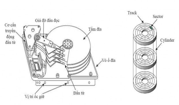
Figure V.1 : Structure of a hard disk
With uniform density recording technology, more information is recorded in tracks farther from the axis of rotation. This recording technology is increasingly used with the advent of intelligent interface standards such as SCSI.
Uneven recording density
Even recording density
Figure V.2: Data recording density on hard disk types
To read or write information to a sector, a movable read/write head is applied to each side of each layer of the disk. These read/write heads are attached to a bar that makes
they move on the same radius of each layer of the disk and thus all these heads are on the tracks of the same radius of the disk layers. The word “cylinder” is used to refer to all the tracks of the disk layers having the same radius and lying on a cylinder.
Since people always want to read magnetic disks quickly, drives usually read more data than they need; this is called read-ahead. To manage the complexities of connecting (or disconnecting) while reading (or writing) information, and reading-ahead, drives need a disk controller.
The magnetic disk manufacturing industry focuses on increasing the capacity of the disk without
The unit of measurement is density per unit surface area.
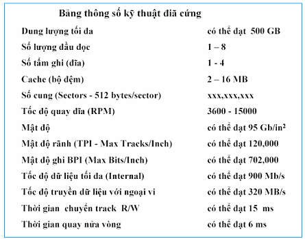
Table V.1: Hard disk specifications
V.3. OPTICAL DISC
Optical storage devices are very suitable for releasing cultural products, backing up data on current computer systems. Born in 1978, this is the product of research cooperation between Sony and Philips in the entertainment industry. From 1980 to now, the optical disc industry has developed strongly in both the entertainment and computer data storage fields. The process of reading information is based on the reflection of low-energy laser beams from the data storage layer. The light receiver will recognize the points where the laser beam is strongly reflected or disappears due to the etched marks (pits) on the disc surface. Strong reflections indicate that there are no etched holes at that point and this point is called the ground point (land). The light receiver in the drive collects the reflected and diffused rays refracted from the disc surface. When the light sources are collected, the microprocessor will translate the light patterns into data bits or sound. The holes on a CD are 0.12 microns deep and 0.6 microns wide (1 micron is one thousandth of a millimeter). The holes are etched in a spiral track with a distance of 1.6 microns between turns, about 16,000 tracks per inch. The pits and lands span about 0.9 to 3.3 microns. The tracks start at the inside and end at the outside in a closed path around the 5mm edges of the disc. Data is stored on a CD in blocks, each containing 2,352 bytes. Of these, 304 bytes contain
information about the synchronization bit, identification bit (ID), error correction code (ECC), error detection code (EDC). The remaining 2,048 bytes contain data. The standard read speed of CD-ROM is 75 blocks/s or 153,600 bytes/s or 150KB/s (1X).
Below are some common types of optical discs.
CD (Compact Disk): Non-erasable optical disc, used in the entertainment industry (digital audio discs). The standard disc has a diameter of 12 cm, the sound played from the disc is about 60 minutes (non-stop).
CD-ROM (Compact Disk Read Only Memory): Non-erasable disk used to store computer data. The standard disk has a diameter of 12 cm, storing data of more than 650 MB. When released, CD-ROM disks already contain content. Normally, CD-ROM disks are used to store software and device control programs.
CD-R (CD-Recordable): Like a CD, a new disc does not contain any information, and the user can write data to the disc once and read it many times. Data on a CD-R disc cannot be erased.
CD-RW (CD-Rewritable): Like a CD, a new disc does not contain any information, and the user can write data to the disc, erase it, and rewrite data on the disc many times.
DVD (Digital Video Disk - Digital Versatile Disk): Born to serve the entertainment industry, the disc contains digitized video images. Today, DVD is widely used in information technology applications. There are two types of disc sizes: 8cm and 12cm. DVD discs can contain data on both sides of the disc, with a maximum capacity of up to 17GB. Technical specifications of DVD-ROM (read-only disc) compared to CD-ROM. The standard reading speed (1X) of DVD is 1.3MB/s (1X of DVD is equivalent to about 9X of CDROM).
DVD-R (DVD-Recordable): Like DVD-ROM, users can write data to the disc once and read it many times. This disc can only record on one side of the disc, the maximum recording capacity on each side is 4.7 GB.
DVD-RW (DVD-Rewritable): Like DVD-ROM, users can record, erase and rewrite data onto the disc multiple times. This disc can also record on one side of the disc, the maximum recording capacity on each side is 4.7 GB.
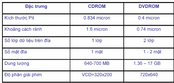
Table V.2: Comparison of some parameters of two types of discs CDROM and DVDROM
With the characteristics of optical discs, the price is increasingly low, considered a suitable medium for distributing software to computers. In addition, optical discs are also used for long-term storage of data to replace magnetic tapes.
V.4. TYPES OF MEMORY CARDS
Nowadays, memory cards are one of the latest technologies used as storage devices. Flash memory cards are a type of EEPROM semiconductor memory (technology used to make BIOS chips on motherboards), which is made up of rows and columns. Each intersection is a memory cell consisting of two transistors, these two transistors are separated by a thin layer of oxide. One transistor is called a floating gate and the other transistor is called a control gate. Floating gates can only be connected to the row (word line) through the control gate. When the connection is established, the bit has a value of 1. To change to a value of 0 is a process called Fowler-Nordheim tunneling. The speed, low power requirements and especially the compact size of memory cards make this type of memory widely used in storage and entertainment technology today.
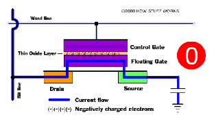
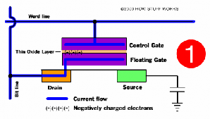
Figure V.3: Illustration of two states of a memory bit in a memory card
V.5. MAGNETIC TAPE
Magnetic tapes have the same technology as magnetic disks but differ from magnetic disks in two ways:
- Access to magnetic disks is random while access to magnetic tapes is sequential. Thus, finding information on magnetic tapes takes more time than finding information on magnetic disks.
- Magnetic disks have limited capacity, while magnetic tapes consist of many reels that can be removed from the tape reader, so the capacity of magnetic tapes is very large (hundreds of GB). With low cost, magnetic tapes are still widely used in backup data storage.
Magnetic tapes, varying in width from 0.38cm to 1.27cm, are packed into rolls and contained in a protective case. The data recorded on magnetic tapes is structured as a number of parallel grooves running along the length of the tape.
There are two ways to record data onto magnetic tape:
Serial recording: with spiral recording, data is recorded sequentially on a track of the magnetic tape, when a track ends, the magnetic tape will rotate back, the magnetic head will record data on the next new track but in the opposite direction. The recording process continues until the magnetic tape is full.
Parallel recording: to increase the speed of reading and writing data on magnetic tape, the read-write head can read and write several adjacent tracks simultaneously. Data is still written vertically on the magnetic tape, but data blocks are considered to be written on adjacent tracks. The number of simultaneous recording tracks on a typical magnetic tape is 9 tracks (8 data tracks - 1 byte and 1 error checking track).
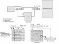
V.6. PERIPHERAL CONNECTION BUS TO PROCESSOR AND INTERNAL MEMORY
In a computer, the processor and internal memory communicate with peripherals using a bus. A bus is a system of connecting cables (about 50 to 100 separate cables) in which a group of cables is defined by different functions including: data lines, address lines, control lines, power supply. Using a bus has two advantages: low cost and easy to change peripherals. People can remove a peripheral or add a new peripheral to computers using the same bus system.
A bus system is cheap to design and implement, since many inputs and outputs share a few simple wires. However, the main disadvantage of buses is that they create bottlenecks, which limit the maximum throughput. Since computer systems for management often use peripherals, the main challenge is to have a bus system that is capable of supporting the processor in communicating with the peripherals.
One of the reasons why designing a bus system is difficult is that the maximum speed of the bus is limited by physical factors such as the length of the bus and the number of components connected to the bus.
Buses are generally of two types: the system bus that connects the processor to memory (system bus, Front Side Bus-FSB) and the peripheral bus (I/O bus) (Figure V.4). I/O buses can be long and can connect to many types of peripherals, which can have different information flows and different data formats. The processor-memory bus is short and usually very fast. In the design phase of the processor-memory bus, the designer knows in advance which components and parts he needs to connect, while the I/O bus designer must design a bus that satisfies many peripherals with very different delays and flows (see Figure V.6).
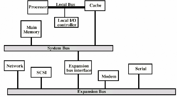
Figure V.4: Bus system in a computer
Currently, in some computer systems, the peripheral bus is divided into two sub-bus systems. In which, the high-speed bus supports the connection of high-speed devices such as SCSI, LAN, Graphic, Video, etc. and the expansion bus system is designed to connect to low-speed peripherals such as modems, serial ports, parallel ports, etc. Between the two peripheral bus systems in the hierarchical bus system organization is a buffer interface (Figure V.5).
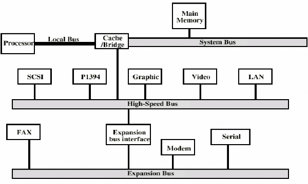
Figure V.5: Hierarchical bus system
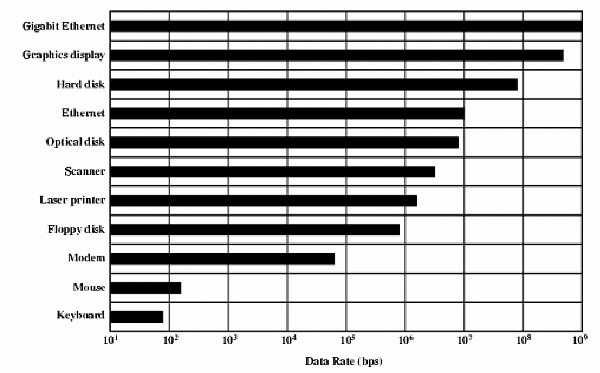
Figure V.6: Table showing data rates of peripherals
We can have many choices in designing a bus, as shown in Table V.3.
Bus characteristics
System bus | Peripheral bus | |
Bus width | Different address and data lines | Address and data lines are multiplexed. |
Data bus width | Wider is faster (e.g. 64 bit) | The narrower the less expensive (e.g. 8 bits) |
Number of words passed | Move multiple words | Simple transfer one word at a time |
Bus owner | Much | One |
Packet transfer | Yes. Need more bus owners. | No. Connect once and transfer all information. |
Pulse | Synchronize | Asynchronous |
Maybe you are interested!
-
 Computer Architecture Course - 10
 -
 Computer Architecture - 27
 -
 Computer Structure - Hanoi Industrial College - 15
 -
 The influence of Indian culture on Chinese Buddhist architecture and sculpture - 14
 -
 Basic Features of Authoring a Computer Program
Table V.3 : Major options for a bus
Table V.3 contains the following concepts related to bus owners - the components that can initiate a read or write operation on the bus. For example, the processor is always a bus owner. A bus has multiple owners when it has multiple processors, or when peripherals can initiate a bus operation. If there are multiple bus owners, then there must be an arbitration mechanism to decide which owner is entitled to the bus. A multi-mastered bus can provide more bandwidth by using packets instead of using the bus for each individual operation. The technique of using packets is called task partitioning (using a packet-switched bus). A read operation is decomposed into a read request operation (which contains the address to be read), and a memory response operation (which contains the information to be read). Each operation has a label indicating the type of operation. In task partitioning technique, while the memory reads information at the specified address, the bus is reserved for other masters.
The system bus is a synchronous bus, consisting of a clock on the control lines, and an algorithm for the addresses and data to the clock. Since there is little or no logic to decide what action to take next, synchronous buses are both fast and cheap. Everything on this bus must operate at the same clock.
In contrast, I/O buses are asynchronous buses, which do not have a synchronous clock in the bus system. Instead, there are handshake protocols with specific timing rules used between the transmitter and receiver of the bus. Asynchronous buses are very adaptable to many peripherals and allow the bus to be extended without worrying about synchronization. Asynchronous buses are also easy to adapt to changes in technology.
V.7. BUS STANDARDS
The number and types of input/output devices are not predetermined in information processing systems. This allows computer users to use the input/output device that meets their requirements. Input/output is the interface over which the devices