Processor | Type | Year of release | L1 Cache a | L2 Cache | L3 Cache |
IBM 360/85 | Mainframe | 1968 | 16 to 32 KB | - | - |
PDP-11/70 | Mini Computer | 1975 | 1 KB | - | - |
VAX 11/780 | Mini Computer | 1978 | 16 KB | - | - |
IBM 3033 | Mainframe | 1978 | 64 KB | - | - |
IBM 3090 | Mainframe | 1985 | 128 to 256 KB | - | - |
Intel 80486 | PC | 1989 | 8 KB | - | - |
Pentium | PC | 1993 | 8KB / 8KB | 256 to 512 KB | - |
PowerPC 601 | PC | 1993 | 32 KB | - | - |
PowerPC 620 | PC | 1996 | 32KB / 32KB | - | - |
PowerPC G4 | PC/Server | 1999 | 32KB / 32KB | 256KB to 1MB | 2 MB |
IBM S390/G4 | Mainframe | 1997 | 32 KB | 256 KB | 2 MB |
IBM S390/G6 | Mainframe | 1999 | 256 KB | 8 MB | - |
Pentium 4 | PC/Server | 2000 | 8KB / 8KB | 256 KB | - |
IBM SP | High-End server/ Super Computer | 2000 | 64KB / 32KB | 8 MB | - |
CRAY MTA b | Super Computer | 2000 | 8 KB | 2 MB | - |
Itanium | PC/Server | 2001 | 16KB / 16KB | 96 KB | 2 MB |
SGI Origin 2001 | High-End server | 2001 | 32KB / 32KB | 4 MB | - |
Maybe you are interested!
-
 Computer Architecture - 27
 -
 Computer Architecture - 11
 -
 Computer Structure - Hanoi Industrial College - 15
 -
 The influence of Indian culture on Chinese Buddhist architecture and sculpture - 14
 -
 Basic Features of Authoring a Computer Program
a Two values separated by “/” indicate the command cache and data cache values
b Both values are instruction caches
Table IV.2 : Cache size of some systems
IV.8. INTERNAL MEMORY
The internal memory satisfies the requirements of cache and is used as an I/O buffer because the internal memory is both a place to store information from the outside and a place to output information to the cache. The performance of the internal memory is measured by the access time and bandwidth. Typically, the access time of the internal memory is an important factor for cache while the bandwidth of the memory is the main factor for I/O operations. With the widespread use of external caches, the bandwidth of the internal memory has also become important for cache.
Although caches require internal memory with small access times, it is often easier to improve memory bandwidth by using new memory organization methods than by reducing cache access times. Caches benefit from bandwidth improvements by increasing the size of each cache block without significantly increasing the cache miss penalty.
The following techniques are used to extend the bandwidth of internal memory:
− Extend the length of internal memory cells. This is a simple technique to increase memory bandwidth. Normally, cache and internal memory have a memory cell width of 1 word because the processor accesses one word of memory cell. Doubling or quadrupling the width of cache and internal memory cells doubles or quadruples the access traffic to the internal memory. So we also have to spend more money to extend the memory bus (the bus connecting the processor to the memory).
An example of a processor with a large internal memory cell length is the ALPHA AXP 21064 processor (DEC). The external cache, internal memory, and memory bus are all 256 bits wide.
− Simple cross-slot memory: memory ICs can be organized into banks to read or write multiple words at once instead of just one word, the width of the bus and cache does not change. When multiple addresses are sent to multiple banks, multiple words can be read at the same time. Cross-slot memory also allows multiple words to be written to the memory at the same time. Simple cross-slot memory organization is less complicated than the normal organization of internal memory because the banks can share the address lines with the memory controller, and thus each bank can use the data part of the memory bus. SDRAM and DDR SDRAM are types of RAM that use this technique.
− Cross-segmented memory organized into independent banks: a more efficient cross-segmented memory organization is to allow multiple memory banks and thus allow the banks to operate independently of each other. Each bank needs separate address lines and sometimes separate data buses: In this case the processor can continue its work while waiting for data (in case of cache failure). RDRAM is this type of memory.
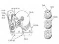
− Avoiding conflicts between memory banks. In multiprocessors and vector computers, the memory system is designed to allow multiple independent access requests. The efficiency of the system depends on the frequency of independent requests to access different banks. With normal overlap (Figure IV.6), sequential accesses or all accesses to addresses that are an even number apart, work well, but problems arise if the addresses are oddly spaced. One approach that mainframe computers take is to reduce the number of static conflicts by increasing the number of banks. For example, the NEC SX/3 divides its internal memory into 128 banks.
Range 0 | Address | Strip 1 | Address | Range 2 | Address | Range 3 | |
0 | 1 | 2 | 3 | ||||
4 | 5 | 6 | 7 | ||||
8 | 9 | 10 | 11 | ||||
12 | 13 | 14 | 15 |
Figure IV.6 : Fourth-order cross-memory.
The ith range contains all words whose addresses satisfy the formula (address) mod 4 = i
IV.9. VIRTUAL MEMORY
Virtual memory defines a mechanism for automatically transferring data between internal memory and external memory (magnetic disk).
In the past, when a program's length exceeded the memory limit, the programmer had to divide his program into self-eliminating sections (overlays) and manually manage the exchange of information between memory and disk. Virtual memory lightens the programmer's load by making this exchange of information happen automatically.
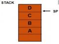
In modern processors, virtual memory is used to allow multiple processes to run simultaneously, each with its own address space. If all of these address spaces were part of the internal memory address space, it would be very expensive. Virtual memory consists of internal and external memory that is broken down into blocks so that each program can be provided with the blocks needed to execute that program. Figure
IV.7 shows a program contained in virtual memory consisting of 4 blocks, 3 of which are in internal memory, the fourth block is on disk.
virtual address physical address internal memory
D
C
A
B
0 A 0
4K
8K
12K
16K
20K
24K
28K
32K
...
... 16M
BCD
...
...
4K
8K
12K
16K
20K
24K
28K
D
Hard disk
virtual memory
Figure IV.7. A program consists of 4 pages A, B, C, D in which page D is located in the disk drive.
In addition to the division of memory space, the need for protection and automatic management of memory levels, virtual memory simplifies the loading of programs into memory for execution through a mechanism called address relocation. This mechanism allows a program to be executed when it is located at any location in memory.
Parameters
Cache | Virtual memory | |
Length of each block (page) | 16 - 128 byte | 4096 - 65536 bytes |
Time to successful penetration | 1 - 2 pulses | 40 - 100 pulses |
Punishment for failure (Penetration Time) (Data Migration) | 8 - 100 pulses 6 - 60 pulses 2 - 40 pulses | 700,000 - 6 million pulses 500,000 - 4 million pulses 200,000 - 2 million pulses |
Failure rate | 0.5% - 10% | 0.00001% - 0.001% |
Capacity | 8KB – 8MB | 16MB – 8GB |
Table IV.3 : Typical quantities for cache and virtual memory.
Compared with cache memory, virtual memory parameters increase from 10 to 100,000 times.
In addition to the quantitative differences we see in Figure IV.9, there are other differences between cache and virtual memory:
- In case of cache failure, the replacement of a block in cache is controlled by hardware, while the replacement in virtual memory is mainly by the operating system.
- The address space that the processor manages is the virtual memory address space, while the cache capacity does not depend on the processor address space.
- External memory is also used to store files in addition to its role as a backend to internal memory (in memory levels).
Virtual memory is also designed with many techniques specific to itself.
Virtual memory systems can be divided into two types: those with fixed-size blocks called pages, and those with variable-length blocks called segments. Page addressing specifies an address within a page, just like cache addressing. Segment addressing requires two words: one containing the segment number and one containing the offset within the segment. Segment addressing is more difficult for compilers.
Because of segment replacement, few computers today use pure segment addressing. Some use a hybrid approach called page segmentation, in which each segment contains an integer number of pages. Now we answer the four questions posed in the memory allocations for virtual memory.
Question 1 : Where is a block located in internal memory?
The virtual memory penalty for failure is equivalent to having to access the disk. This access is very slow, so a fully coordinated approach is chosen, in which blocks (pages) can be located anywhere in the internal memory. This gives a low failure rate.
Figure IV.8: Mapping virtual pages into physical memory
Question 2 : How to find a block when it is in internal memory ?
Page and segment addressing both rely on a data structure in which the page number or segment number is indexed. For page addressing, based on the page table, the physical address is finally determined by contiguating the physical page number with the address within the page (Figure IV.9). For segment addressing, based on the information in the segment table, a validation of the address is performed. The final physical address is determined by adding the segment address and the address within the segment (intra-segment offset) (Figure IV.10).
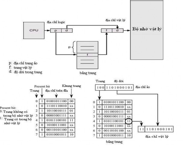
Figure IV.9 : Illustration of address mapping between virtual memory and physical memory in page allocation
Paragraph table
Limit | Base |
S
D
CPU |
logical address
S: segment address in virtual memory
D: segment length in virtual memory Limit: maximum segment limit Base: displacement in segment
<
wrong
correct
INTERNAL MEMORY
+
Physical address
Figure IV.10 : Address mapping between virtual memory and physical memory in segment allocation
Question 3 : Which block must be replaced when there is a page failure ?
Most operating systems try to replace the least recently used block (LRU: Least Recently Utilized) thinking that this is the block that is least needed.
Question 4 : What happens when data needs to be recorded ?
The write strategy is always a write-back, meaning that information is only written to a block of internal memory. A block with changed information is copied to the magnetic disk if the block is replaced.
IV.10. PROTECTING PROCESSES USING VIRTUAL MEMORY
The advent of multiprogramming, in which computers run multiple programs in parallel, introduced new requirements for protection and separation between programs.
Multiprogramming introduces the concept of a process: a process consists of a running program and all the information needed to continue executing this program.
In multiprogramming, the processor and internal memory are shared interactively by multiple users at the same time, to create the impression that each user has his or her own computer. And so, at any time, it must be possible to switch from one process to another.
A process must operate correctly, whether it is executed continuously from start to finish, or whether it is interrupted by other processes. The responsibility for ensuring that processes run correctly is shared between computer designers and operating system designers. Computer designers must ensure that the processor can maintain and restore the state of processes, and operating system designers must ensure that processes do not interfere with each other. Operating systems solve this problem by dividing up internal memory among processes, and each process's state is present in its allocated memory. This means that operating system designers must work with computer manufacturers to protect one process from being affected by another.
Computer designers have three additional responsibilities that help operating system designers protect processes:
1. Provides two operating modes that indicate whether the process being executed is a user process or a system (operator) process.
2. Provide a subset of processor state that the user process can use but not modify.
3. Provide mechanisms to be able to switch from user mode to
operator and vice versa.
As we have seen, the address given by the processor must be converted from a virtual address to a physical address. This takes the hardware a step further in protecting processes. The simplest way to do this is to allow the user process to manipulate the access permission bits on each page or segment. When the processor issues a read (or write) signal and a user (or system) signal, it is easy to detect intrusions.
unauthorized access to memory before it causes damage. Processes are protected and have their own page tables that point to separate pages in memory.
*****
CHAPTER IV REVIEW QUESTIONS AND EXERCISES
*****
1. What is the difference between SRAM and DRAM? Where are they used in computers?
2. What is the purpose of memory levels?
3. State two principles on which cache operates.
4. Given a direct correspondence cache with 8 blocks of 16 bytes each. The internal memory has 64 blocks. Suppose that at boot time, the first 8 blocks of the internal memory are brought into cache.
a. Write the label table of the blocks currently in the cache
b. The CPU reads the following addresses in turn: O4AH, 27CH, 3F5H. If it fails, update the label table.
c. The CPU uses the write-back method. When the cache fails, the CPU uses the write-with-load method. Describe the job of the cache manager when the CPU issues the following words to write into the internal memory: 0C3H, 05AH, 1C5H.
5. What are the main causes of cache failure?
6. What are the solutions to ensure data consistency in multiprocessor systems with shared memory?
7. Ways to expand the bandwidth of internal memory?
8. Why use virtual memory?
9. What is the difference between cache and virtual memory?