In there:
+ Select concrete for column neck and foundation of durability level B22.5 (grade 300) with R b = 130 kg/cm 2 ; R bt = 10 kg/cm 2 .
+ = (0.7÷0.9), is the longitudinal bending coefficient, approximated by = 0.9
=> Choose b c = 200; l c = 300
N
tt 0
Q tt
0
M
tt 0
L
ptt
min min
=n.
p
tc
p tt = 12.4T/m 2
p
tt
tc
min
max max
=n.
p
p tt
p tt
max
=28.4T/m 2
1
p tt
2
l c
L xt
L m = 2.5m
45°
H m
h m
45°
2.2.7.2 Determination of H m according to bending strength conditions
b c
B xt
B m = 1.8m
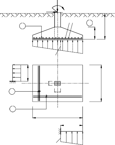
Figure 2.11: Diagram to determine the working height of the foundation
- Effective height of foundation according to bending strength condition:
In there:
+ L =
H 0 L
1tb
p tt .L tt
0.4R l tr
b
L m l c
2
2.5 0.3 = 1.1m
2
+ L tt = L m = 2.5m;
+ l tt = l c = 0.3m;
+ R b = 130 kG/cm 2 = 1300 T/m 2
p
+
1tb
tt tt
p p
1 max
2
21.4 28.4
2
=24.9 T/m 2
p
p
+
tt tt
1 min
tt max
p
tt min
)( L m l c )
(p
2L
m
= 12.4 (28.4 12.4)( 2.5 0.3) =21.4 T/m 2
2.2.5
=> H 0
1.1
= 0.70m
24.9.2.5
0.4.1300.0.3
- Select H m according to bending strength conditions:
H m = H 0 + ( /2 + a bv ) = 0.70 + 0.05 = 0.75m
2.2.7.3 Determine H m according to the penetration condition
- Determine the size of the penetration tower:
+ B xt = b c + 2H 0 = 0.2 + 2.0.7 = 1.6m;
+ L xt = l c + 2H 0 = 0.3 + 2.0.7 = 1.7m
- Determine the penetrating force: To be safe, we only need to consider one side in the direction of the long edge with the force P tt max .
N gxt = F outside XT . P tt 2tb = B
.( L m L xt ).p tt
m2 2tb
N gxt = 1.8.( 2.5 1.7 ).27.1 =19.5 T;
2
In there:
p tt p tt
25.8 28.4 2
p
+
tt
2tb
2 max
2
=27.1 T/m
2
p
p
+
tt tt
2 min
tt max
p
tt min
)( L m L xt )
(p
2L
m
= 12.4 (28.4 12.4)( 2.5 1.7 ) =25.8T/m 2
2.2.5
- Determine the penetration resistance:
N cxt = 0.75.R bt .H 0 . b c B xt =0.75.100.0.7. 0.2 1.6 = 47.3T
2 2
- Check the penetration condition: N cxt = 47.3T ≥ N gxt = 19.5 T
- So the selected foundation height satisfies the penetration condition.
2.2.8 Steel calculation
2.2.8.1 Calculation of reinforcement according to the side direction L m
- Bending moment along the side L m
M 1 .p tt .B .(L l ) 2 = 1 .24,9.1,8.(2.5 0.3) 2 = 27.1 Tm
L8 1tb mmc8
In there:
p
p
+
tt tt
1 min
tt max
tt min
)( L m l c )
(p
p
2L
m
= 12.4 (28.4 12.4)( 2.5 0.3) =21.4 T/m 2 .
2.2.5
p
+
1tb
p tt p tt
1 max =
2
21.4 28.4
2
=24.9 T/m 2 .
- Steel reinforcement calculated according to side direction L m
tt M
M 27.1.10 52
A sL LL = 15.4 cm
R s H 0 0.9.R s H 0 0.9.2800.70
- Reinforcement steel structure according to L m direction
A
ct
sL min
.B m
.H 0
= 0.1%.180.70 = 12.6 cm 2
- Steel reinforcement arranged in the direction of edge L m
A sL = max ( A ct ; A tt ) = 15.4 cm 2
sL sL
- Selecting steel arrangement 12 we have: f a
1.2 .3.14 1.13 cm 2
2
4
- Total number of steel bars in L m direction :
n A sL = 15.4 = 14 bars
f
a
L 1.13
- Reinforcement step in L m direction :
@ L =
B m 100 1800 100 = 130
nL 1
14 1
- So the steel is arranged along the edge L m direction : 12@130
2.2.8.2 Calculation of reinforcement according to side direction B m
- Bending moment along side B m
M 1 .p tt .L .(B b ) 2 = 1 .20,4.2,5.(1.8 0.2) 2 = 16.3 Tm
B 8 tb mmc8
In there:
tt p tt p tt
12.4 28.4 2
+ p tb min max=
2
=20.4 T/m .
2
- Steel reinforcement calculated according to side direction B m

tt M
M 16.3.10 52
A sB BB = 9.2 cm
R s H 0 0.9.R s H 0 0.9.2800.70
- Steel reinforcement is constructed according to the direction of edge B m
A
ct
sB min
.L m
.H 0
= 0.1%.250.70 = 17.5 cm 2
- Steel reinforcement arranged in the direction of edge B m
A sB = max ( A ct ; A tt ) = 17.5 cm 2
sB sB
- Selecting steel arrangement 12 we have: f a
1.2 .3.14 1.13 cm 2

2
4
- Total number of steel bars in direction B m :
n A sB = 17.5 = 16 bars


f
a
B 1.13
- Reinforcement step in direction B m : @ B =
L m 100 2500 100 = 160


nB 1
- So the steel is arranged along the edge direction Bm: 12@160
-
16 1
N
tt 0
Q tt tt
H m
1 @130
0 M 0
h m
@1602
p tt = 12.4T/m 2
p
min
B
L
tt
p
m
tb
.p tt 1
tt max
=28.4T/m 2
c
b c
B m = 1.8m
2 @160 l
1 @130
L m = 2.5m
.p tt
L
B m .p tt
B m 1
max
Figure 2.12: Steel calculation diagram

2.2.9 Drawing representation

40Þ
Column steel
± 0.000
300
-0.300
NATURAL GROUND
1250
Þ8@100 3
Tripod
-2,300
2000
500
2 Þ12@160
50
300
400 50
Þ12@130 1
100250
BT STONE LINING 4x6 M100 100 THICK
100
1250 1250
2500
BB CROSS SECTION
TL:1/25
100
900
100
400
1800
300
50 1 50150 50
B 50 200 200 50 B
900
Þ12@160 2
100
Þ12@130 1
100 1250 1250
2500
100

NOTE:
NAIL (1800x2500)
TL:1/25
* STONE CONCRETE 10X20 GRADE 250 (DURABILITY LEVEL B20)
* STEEL < 10 .Rs = 2250 kg/cm2 (AI STEEL)
* STEEL >= 10 .Rs = 2800 kg/cm2 (AII STEEL)
Figure 2.13: Drawing showing single foundation
Chapter 3
PILE FOUNDATION DESIGN
3.1 LOW PILE FOUNDATION DESIGN PROCEDURE
3.1.1 Determine the load on the foundation
- The load on the foundation can be at the natural ground level or the top of the foundation. When determining the load on the foundation, it is necessary to determine the load combination for the most dangerous calculated internal force as follows:
N tt
N tt
N tt
M
max
practice
practice
M
TT
Q tt
or
tt max
Q tt
or
TT
M
Q tt
(3.1)
practice
practice
max
- The standard is divided into 2 types of loads:
+ Standard load: Used for calculation and testing according to TTGH II.
+ Design load: Used for calculation and testing according to TTGH I.
N tt Ntc
0 0
0
M tt
Q tt
= n M tc
0
Q tc
(3.2)
0 0
with n = 1.15 being the average overload factor.
3.1.2 Assessment of topographic, geological and hydrological conditions
3.1.2.1 Terrain conditions
- Current terrain conditions of the construction site at a scale of 1/500 need to be clarified:
Before and after filling;
- Underground pipes, equipment, ... passing through the construction site.
3.1.2.2 Synthesis of geological and hydrological survey data for design
Based on the "Construction geological survey report" the designer
Synthesize necessary data for foundation design calculations:
- Field test parameters:
+ Penetration test: static penetration test (CPT) and standard penetration test (SPT);
+ Field test (if any): Static axial compression test,
Field compression test, horizontal compression test.
- Laboratory test parameters:
+ Physical indicators: Types of bulk density , specific gravity , humidity W, limits
yield limit W l , plastic limit W p , saturation, porosity, void ratio and other parameters
Numbers to evaluate soil condition such as: relative density D, consistency I l , index
plastic I p .
+ Strength indicators: Internal friction angle , adhesion force c;
+ Deformation indicators: Total deformation modulus E 0 , compression coefficient a, relative compression coefficient a 0 , compression-settlement relationship charts such as: e - p, a 0 – p; a - p,..;
- Groundwater level (if any) is shown in geological cylinders. Design work must take into account seasonal and temporal changes in groundwater level.
- Geological cross-section, borehole cylinders, borehole layout plan.
3.1.3 Select the depth of the base of the platform (h m )
- Normally, the depth of the pile foundation should not be too shallow or too deep. The depth of the pile foundation is usually chosen as h m = (1.0 – 3.0) m and satisfies the condition h min .
Natural ground
Q tt
tt
N
0 tt
0 M 0
h m
E p
L c
Figure 3.1: Depth of pile foundation
- For low pile foundations, when choosing the depth of the foundation, it is important to note that h m is large enough so that the shear force Q tt 0 is balanced with the soil pressure, meaning:
0
γB m
2Q tt
φ
In there:
h m h min = 0.7tg(45 0 - )
2
(3.3)
+ : Unit weight of soil on the foundation bottom;
+ : Internal friction angle of soil on the bottom of the foundation;
+ B m : Foundation width, initially can assume B m = 5d (d: edge or line)
pile glass).
+ Q tt 0 : Shear force transmitted to the foundation.
3.1.4 Selection of pile type, pile material, construction method and expected depth of lowering
pile
3.1.4.1 Selection of pile type, materials and construction methods
a) Concrete piles
- Reinforced concrete square piles are usually constructed by driving or
pressed, bored pile: Grade 250 (B20);
- Prestressed centrifugal concrete piles: Grade 600 (B50);
b) Pile reinforcement
- Reinforced steel: is ribbed steel, commonly used types:
+ AII; AIII; AIV;
+ SD295; SD390; SD490;
+ CB300; CB400; CB500-V;
- Belt: Usually use AI; CI smooth steel
Table 3.2: Design strengths of concrete R b, R bt when calculating according to the first limit states, MPa (according to TCVN 5574:2012)
Status
Concrete type | Compressive strength grade of concrete | ||||||||||
B15 | B20 | B25 | B30 | B35 | B40 | B45 | B50 | B55 | B60 | ||
M200 | M250 | M350 | M400 | M450 | M500 | M600 | M700 | M700 | M800 | ||
Axial compression (tensile strength) R b | Heavy concrete, fine grain concrete | 8.5 | 11.5 | 14.5 | 17.0 | 19.5 | 22.0 | 25.0 | 27.5 | 30.0 | 33.0 |
Drag along R axis bt | Concrete heavy | 0.75 | 0.90 | 1.05 | 1.20 | 1.30 | 1.40 | 1.45 | 1.55 | 1.60 | 1.65 |
Group A small grain | 0.75 | 0.90 | 1.05 | 1.20 | 1.30 | 1.40 | - | - | - | - | |
Group B small grain | 0.64 | 0.77 | 0.90 | 1.00 | - | - | - | - | - | - | |
Group C small grain | 0.75 | 0.90 | 1.05 | 1.20 | 1.30 | 1.40 | 1.45 | 1.55 | 1.60 | 1.65 | |
Maybe you are interested!
-
 Environmental impact assessment of Thanh Minh industrial cluster infrastructure investment project, Phu Tho town, Phu Tho Province - 2
 -
 Assessment of the Quality of Sustainable Tourism Development Factors in Nghe An Province from Provincial Tourism Management Officers
 -
 Assessment of the World Trade Organization's Dispute Settlement Mechanism for Developing Countries
 -
 Assessment of surface water resources in Dong Nai river basin to serve sustainable development goals in the context of climate change - 2
 -
 Respondents' Assessment of Operational Risk Management at Agribank Quang Tri Province Branch