PREFACE
The forklift is a type of machine whose main function is to lift and move objects over a short distance. It plays an important role in improving labor productivity, reducing human labor, improving product quality and reducing costs.
Lifting machines are very popular equipment used in production facilities in general. This is the most important equipment in the issue of mechanization, automation of lifting and unloading operations of all kinds of workpieces, raw materials, equipment, goods... On ships, cars. In machine manufacturing workshops, shipbuilding and on construction works, seaports... The reliability of the equipment directly affects the safety of people when operating. Therefore, learning and researching lifting machines is indispensable for all engineers. And this explains that Lifting Machine is one of the compulsory basic subjects in the framework of the undergraduate training program of Mechanical Engineering in general and Mechanical Engineering majors: Ship Power, Automobile Power, Machine Manufacturing, Shipbuilding...
The lecture “Lifting and Transferring Machines” provides some basic knowledge about the structural characteristics, operating principles, scope of use and design calculation methods of common machine part clusters in lifting machines as well as popular lifting machines today. At the same time, the lecture “Lifting and Transferring Machines” is a teaching, learning and research document for mechanical majors being trained at Nam Dinh University of Technical Education including: Automotive Technology, Machine Manufacturing Technology, Welding Technology.
However, the issues presented in this lecture series may still have many limitations and errors. We hope to receive sincere comments from teachers in the school and students to help us further improve this lecture series.
AUTHOR TEAM
CHAPTER 1: LIFTING MACHINE DETAILS AND EQUIPMENT 4
1.1. Basic characteristics of the lift 4
1.1.1. Payload Q 4
1.1.2. Service area 4
1.1.3. Movement speeds 5
1.1.4. Working mode… 5
1.2. Structure and components of the lifting mechanism 8
1.2.1. Lifting mechanism diagram 8
1.2.2. Static and dynamic relations 10
1.3. Load-carrying part 12
1.3.1. Hook 13
1.3.2. Pair of holders 20
1.4. Rope in lifting mechanism 25
1.4.1. Braided steel cable 26
1.4.2. Welding chain 31
1.4.3. Plate chain 33
* Compare cable and chain 34
1.5. Wire guide and reel 35
1.5.1. Tang 35
1.5.2. Pulleys and sprockets 39
1.5.3. Hoist 43
1.6. Braking device 45
1.6.1. Ratchet mechanism 46
1.6.2. Braking torque in lifting mechanism 50
1.6.3. Brake pads 54
1.6.4. Belt brake 64
1.6.5. Axle pressure brake 71
1.6.6. Automatic braking 74
1.6.7. Safety crank 77
1.7. Lifting mechanism 78
1.7.1. Manual drive mechanism 79
1.7.2. Electric drive mechanism 81
1.7.3. Machine opening process in lifting mechanism 82
1.7.4. Lift mechanism braking process 86
1.7.5. Structural characteristics of lifting mechanism 87
CHAPTER 2: COMMON SPINDLE MACHINES 90
2.1. Simple lifting equipment 90
2.1.1. Size 90
2.1.2. Winch 94
2.2. Hoist 98
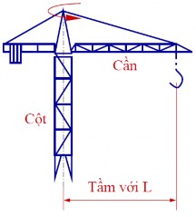
2.3. Cranes and jib cranes 103
2.3.1. Crane 103
2.3.2. 116 slewing crane
2.3.3. Calculation of metal structures in common cranes 126
CHAPTER 3: CONTINUOUS TRANSFER MACHINE 127
3.1. Transfer machine with traction device 128
3.1.1. General concepts 128
3.1.2. Calculation of traction force 131
3.1.3. Drive and tensioning parts 134
3.1.4. Conveyor 136
3.1.5. Chain conveyor 137
3.1.6. Vertical conveyor 140
3.2. Transfer machine without traction device 141
3.2.1. Roller conveyor 141
3.2.2. Inertia transfer machine 142
3.2.3. Screw type converter 143
CHAPTER 1: LIFTING MACHINE DETAILS AND EQUIPMENT
1.1. Basic characteristics of the lift
1.1.1. Payload Q
The crane's load capacity is the maximum nominal weight of the load (lift object) that the machine can lift according to design calculations.
Load ranges (in Tons) are standardized in load ranges
following weight:- - | - | - | - | - | - | 0.05 | - | - | |
0.1 | - - | 0.2 | 0.25 | 0.32 | 0.4 | 0.5 | 0.63 | 0.8 | |
1 | 1.25 | 1.6 | 2 | 2.5 | 3.2 | 4 | 5 | 6.3 | 8 |
10 | 12.5 | 16 | 20 | 25 | 32 | 40 | 50 | 63 | 80 |
100 | 125 | 160 | 200 | 250 | 320 | 400 | 500 | 630 | 800 |
140 | 180 | 225 | 280 | 360 | 450 | 550 | 710 | 900 |
Maybe you are interested!
-
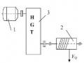
 Machine part principle 2 - 1
 -
 Study on the influence of some factors on specific energy cost and surface roughness when milling flat surfaces with face milling cutters on milling machine TUM 20VS - 1
 -
 Machine part principle 2 - 2
 -
 Preparation: Machine, Cutting Tools, Measuring Tools, Fixtures and Workpieces According to the Requirements of the Box Detail to Be Machined.
 -
 How to Determine Stress Generated in Machine Parts
1000
1.1.2. Service area
a. Lifting height H
Lifting height H is the distance from the vertical machine level to the center of the load-carrying device at its highest position. For cranes with booms, the lifting height varies depending on the reach.
b. Aperture L
The span L is the horizontal distance between the axes of the two rails on which the machine moves.
c. Journey S
L
The travel is the distance to be moved along the rail (with the crane being the rotation angle)
H
S
Figure 1.1: Bridge crane diagram
Figure 1.2: Crane diagram |
1.1.3. Movement speeds
The working speed of each mechanism in each machine shaft depends on the nature of the work, the function of the machine and the working mode of the machine.
In general-purpose cranes today, the speeds are as follows:
+ Lifting speed does not exceed 25 ÷ 30 m/min
+ Car speed on the bridge is 35 ÷ 50 m/min
+ Bridge moving speed 100 ÷ 120 m/min
+ Rotation speed (for crane): n q = 0.5 ÷ 3.0 rpm
1.1.4. Working mode
The characteristics of the crane are that it works in a intermittent, repetitive, cyclical manner. In addition, each machine is used with different loads, different usage time ratios and working intensities... Therefore, they are classified into different working mode groups. Working mode is a very important characteristic of the crane. It is reflected in each step of calculating the design of the mechanisms as well as the metal structure. The crane is designed, manufactured and used in the correct working mode to ensure safety and economic efficiency.
Each mechanism of a crane can be used with different modes. The general mode for the crane is taken from the usage mode of the lifting mechanism.
a. Classify working regimes according to targets
The shaft mechanisms are divided into two groups:
Group 1: hand crank drive with hand crank mode
Group 2: motor driven with 4 modes: light, medium, heavy and
very heavy
To classify working modes use the following criteria:
1. Load factor
K Q tb
Q Q
In there:
Q tb _ average weight of the object lifted in 1 working shift. Q _ nominal load of the machine.
2. Annual utilization rate
k = Number of working days in a year
n365
3. Daily usage coefficient
k = Number of working hours per day
ng24
In addition, there are criteria to evaluate the usage mode of electric motors.
4. Engine closing time
TD % T 0 100%
T
T 0 _ motor closing time in one operating cycle of the machine
T 0 = Σt m + Σt v
T _ cycle operating time
T = Σt m + Σt v + Σt p + Σt d
In there:
Σt m _ total machine on time
Σt v _ total time of movement at steady velocity
Σt p _ total braking time
Σt d _ total downtime
5. Number of times the machine is opened in 1 hour (m)
6. Number of cycles in 1 hour (a ck )
7. Ambient temperature (t 0 )
The data of the characteristic indicators of the working mode are given in Table 2.
This classification is complex, based on too many criteria and hardly reflects the diversity of crane usage.
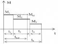
Table 2: Typical indicators of usage mode
Indicators
Usage mode | ||||
Light | Medium | Heavy | Very heavy | |
K Q | 0.25-1.0 | 0.75 | 0.75-1.0 | 1.0 |
K n | ~ 0.25 | 0.5 | 0.75 | 1.0 |
no | ~ 0.33 | 0.67 | 0.67 | 1.0 |
% | 15 | 25 | 40 | 40-60 |
m times/h | 60 | 120 | 240 | 360 |
a ck /h | 10-15 | 20-25 | 30-35 | 40 |
t 0 C | 25 | 25 | 25 | 45 |
b. Classification of structures according to international standards (ISO)
Based on the following two criteria:
1. Usage level: characterized by the total number of hours the mechanism is used. During the entire machine life. There are 10 usage levels (table 3) from T 0 to T 9 .
Table 3. Level of use of the structure
Usage level
Total usage time (h) | Note | |
T 0 | 200 | Rare, irregular use |
T 1 | 400 | |
T 2 | 800 | |
T 3 | 1600 | |
T 4 | 3200 | Use lightly and regularly |
T 5 | 6300 | Use intermittently, regularly |
T 6 | 12500 | Use tense, abnormal |
T 7 | 25000 | Use tension |
T 8 | 50000 | |
T 9 | 100000 |
t P
2. Load status of the structure: characterized by the load factor
K t i
P i
m
In there:
i max
P i _ load levels,
t i _ load bearing time (table 3) symbols from L 1 to L 4
Table 4: Nominal load factors for structures
Loading status
K m | Note | |
L 1 – light | 0.125 | The structure rarely bears maximum load, through usually light load |
L 2 – medium | 0.25 | Relative maximum load bearing structure many, usually moderate load |
L 3 – heavy | 0.5 | The structure is often under maximum load, usually heavy duty |
L 4 – very heavy | 1.0 | Structure regularly bears maximum load |
The operating mode group is classified based on the combination of the above 2 criteria - there are 8 operating modes of the mechanism (Table 4) denoted from M 1 to M 8.
Table 5: Working mode groups of the mechanism
Status
load
Usage level | ||||||||||
T 0 | T 1 | T 2 | T 3 | T 4 | T 5 | T 6 | T 7 | T 8 | T 9 | |
L 1 | M 1 | M 2 | M 3 | M 4 | M 5 | M 6 | M 7 | M 8 | ||
L 2 | M 1 | M 2 | M 3 | M 4 | M 5 | M 6 | M 7 | M 8 | ||
L 3 | M 1 | M 2 | M 3 | M 4 | M 5 | M 6 | M 7 | M 8 | ||
L 4 | M 2 | M 3 | M 4 | M 5 | M 6 | M 7 | M 8 | |||
Approximate correspondence between the two classifications of working mode groups: M 1 – manual; M 2 , M 3 – light; M 4 , M 5 – medium; M 6 , M 7 – heavy and M 8 – very heavy.
1.2. Structure and components of lifting mechanism
1.2.1. Lifting mechanism diagram
The lifting mechanism of all existing cranes is constructed according to the same principle diagram (Figure 1.3a).
According to this diagram, the lifting mechanism consists of a cylindrical drum with a rope (cable or chain) on it, an object hanging at the end of the rope, and a shaft with a crank at the end. The tension force T 0 on the rope is equal to the weight Q of the object, causing a moment on the drum shaft.
M P
T o
M v
Q
T o
M o
M P
Q
i o
Because
R
Because
P
R
P
a) b)
M v
T'o
M P
i o
T" o
Q
M P
i o
Because
Because
M v
R
R
P P
Q
c) d)
Figure 1.3: Lifting mechanism diagram