INTRODUCTION
Machine principles and machine parts are two of the fundamental subjects taught in technical colleges and universities. It is not only the basis for a series of mechanical engineering subjects but also builds the scientific thinking potential for future engineers and scientists.
Nowadays, to meet the new requirements for quality training standards in the region, especially in vocational teacher training (RAVTE). Nam Dinh University of Technology Education is directing a comprehensive reform of teaching and learning according to the new training process (credit system), in which the subject Principles - Machine Parts 2 is included in teaching for students majoring in mechanics, after completing the basic subjects, Drawing - Technical Drawing, Tolerance - Measurement, Mechanics 1, Technical Materials 1, Principles - Machine Parts 1...
Lecture series Principles - Machine Details 2 compiled with 2 credits includes three parts:
Maybe you are interested!
-
 Machine part principle 2 - 2
 -
 Car body electrical practice - 8
zt2i3t4l5ee
zt2a3gs
zt2a3ge
zc2o3n4t5e6n7ts
If the voltage is out of specification, replace the wire or connector.
If the voltage is within specification, install the front fog light relay and follow step 5.
Step 5 Check the front fog light switch
- Remove the D4 connector of the fog light switch
- Use a multimeter to measure the resistance of the front fog light switch.
Measurement location
Condition
Standard
D4-3 (BFG) -D4-4 (LFG)
Light switchFront Fog OFF
>10kΩ
D4-3 (BFG) -D4-4 (LFG)
Front fog light switchON
<1 Ω
- Standard resistor
D4 connector is located on the combination switch assembly.
If the resistance is out of specification, replace the combination switch (the fog light switch is located in the combination switch).
If the resistance is within specification, follow step 6.
Step 6 Check wiring and connectors (front fog light relay-light selector switch)
- Disconnect connector D4 of the combination switch assembly
- Use a voltmeter to measure the voltage value of jack D4 on the wire side.
Measurement location
Control modecontrol
Standard
D4-3 (BFG) - (-) AQ
TAIL
11 to 14 V
D4 connector for the wiring of the combination switch assembly
If the voltage does not meet the standard, replace the wire or connector.
If the voltage is within standard, there may have been an error in the previous measurements.
Step 7 Check the front fog lights
- Remove the front fog light electrical connector.
- Supply battery voltage to the fog lamp terminals
Jack 8, B9 of front fog lamp on the electrical side
blind first.
Power supply location
Terms and Conditions
Battery positive terminal - Terminal 2Battery negative terminal - Terminal 1
Fog lightsbefore morning
- If the light does not come on, replace the bulb.
If the light is on, re-plug the jack and continue to step 8.
Step 8 Check wiring and connectors (relay and front fog lights)
- Disconnect the B8 and B9 connectors of the front fog lights.
- Use a voltmeter to measure voltage at the following locations:
Measurement location
Switch location
Terms and Conditions
B8-2 - (-) AQ
Electric lock ON TAIL size switchFog switch ON
11 to 14 V
B9-2 - (-) AQ
Electric lock ONTAIL size switch Fog switch ON
11 to 14 V
B8 and B9 connectors on the front fog lamp wiring side
Voltage is not up to standard, repair or replace the jack. If up to standard, there may have been an error in the measurement process.
2.2.4. Procedure for removing, installing and adjusting fog lights 1. Procedure for removing
- Remove the front inner ear pads
Use a screwdriver to remove the 3 screws and remove the front part of the front inner ear liner
-Remove the fog light assembly
+ Disconnect the connector.
+ Use a screwdriver to remove 3 screws to remove the fog light cover
2. Installation sequence
-Rotate the fog lamp bulb in the direction indicated by the arrow as shown in the figure and remove the fog lamp from the fog lamp assembly.
-Rotate the fog light bulb in the direction indicated by the arrow as shown in the figure and install the light into the fog light assembly.
- Use a screwdriver to install the fog light cover
-Install the electrical connector
Attention: Be careful not to damage the plastic thread on the lamp assembly.
- Install the front inner ear pads
Use a screwdriver to install the front inner bumper with 3 screws.
3. Prepare the vehicle to adjust the fog light convergence. Prepare the vehicle:
- Make sure there is no damage or deformation to the vehicle body around the fog lights.
- Add fuel to the fuel tank
- Add oil to standard level.
- Add engine coolant to standard level.
- Inflate the tire to standard pressure.
- Place spare tire, tools and jack in original design position
- Do not leave any load in the luggage compartment.
- Let a person weighing about 75 kg sit in the driver's seat.
4. Prepare to check the fog light convergence
a/ Prepare the vehicle status as follows:
- Place the car in a dark enough place to see the lines. The lines are the dividing line, below which the light from the fog lights can be seen but above which it cannot.
- Place the car perpendicular to the wall.
- Keep a distance of 7.62 m between the center of the fog lamp and the wall.
- Park the car on level ground.
- Press the car down a few times to stabilize the suspension.
Note: A distance of approximately 7.62 m is required between the vehicle (fog lamp center) and the wall to adjust the convergence correctly. If the distance of 7.62 m cannot be achieved, set the correct distance of 3 m to check and adjust the fog lamp convergence. (Since the target area varies with the distance, please follow the instructions as shown in the figure.)
b/ Prepare a piece of thick white paper about 2 m high and 4 m wide to use as a screen.
c/ Draw a vertical line through the center of the screen (line V).
d/ Set the screen as shown in the picture. Note:
- Keep the screen perpendicular to the ground.
- Align the V line on the screen with the center of the vehicle.
e/Draw the reference lines (H, V LH and V RH lines) on the screen as shown in the figure.HINT:
Mark the center of the fog lamp on the screen. If the center mark cannot be seen on the fog lamp, use the center of the fog lamp or the manufacturer's name mark on the fog lamp as the center mark.
H line (fog light height):
Draw a line across the screen so that it passes through the center mark. Line H should be at the same height as the center mark of the fog light bulb.
Line V LH, V RH (center mark position of left fog lamp LH and right fog lamp RH):
Draw two lines so that they intersect line H at the center marks.
5. Check the fog light convergence
a/ Cover the fog lamp or remove the connector of the other side fog lamp to prevent light from the unchecked fog lamp from affecting the fog lamp convergence test.
b/ Start the engine.
c/ Turn on the fog lights and make sure that the dividing line is outside the standard area as shown in the drawing.
6. Adjust the fog light convergence
Use a screwdriver to adjust the fog light to the standard area by turning the toe adjustment screw.
Note: If the screw is adjusted too far, loosen it and then tighten it again, so that the last rotation of the light adjustment screw is clockwise.
3. Self-study questions
1. Describe the operating principle of the lighting system with automatic headlight function
2. Describe the operating principle of the lighting system with the function of rotating headlights when turning
3. Draw diagram and connect lighting system on Hyundai Porter car
4. Draw diagram and connect lighting system on Honda Accord 1992
5. Draw the lighting circuit on a 1993 Toyota Lexus
LESSON 3 MAINTENANCE AND REPAIR OF SIGNAL SYSTEM
I. IMPLEMENTATION GOAL
After completing this lesson, students will be able to:
- Distinguish between types of signals on cars
- Correctly describe common symptoms and suspected areas causing damage.
- Connecting signal circuits ensures technical requirements
- Disassemble, install, check, maintain and repair the signal system to ensure technical requirements.
- Ensure safety in work and industrial hygiene
II. LESSON CONTENT
1. General description
The signal system equipped on cars aims to create signals to notify other vehicles participating in traffic about the vehicle's operating status such as: stopping, parking, braking, reversing, turning...
Signals are used either by light such as headlamps, brake lights, turn signals….. or by sound such as horns, reverse music….
Just like the lighting system. A signal system circuit usually consists of: battery, fuse, wire, relay, electrical load and control switch. Only some switches of the signal system are on the combination switch. The switches of other signals are usually located in different locations such as in the gearbox or brake pedal……
2. Maintenance and repair
2.1. Turn signals and hazard lights
The installation location of the turn signal is shown in Figure 3.1. The turn signal control switch is located in the combination switch under the steering wheel. Turning this switch to the right or left will make the turn signal turn right or left.
The hazard light switch is used when the vehicle has a problem while participating in traffic. When the hazard light switch is turned on, all the turn signals on the vehicle will light up at a certain frequency. The hazard light switch is usually placed separately from the turn signal switch (some old cars integrate the hazard and turn signal switches on the same combination switch cluster).
Figure 3.1 Turn signal switch Figure 3.2 Hazard switch
The part that generates the flashing frequency for the lights is called a turn signal relay. The turn signal relay usually has 3 terminals: B (positive power supply); E (negative power supply); L (providing the turn signal switch to distribute to the
lamp)
2.1.1. Circuit diagram
To generate the frequency for the turn signal, a turn signal relay is used in the turn signal circuit. The current from the turn signal relay will be sent to the turn signal switch assembly to distribute the current to the turn signal lights for the driver's purpose.
Figure 3.3. Schematic diagram of a turn signal circuit without a hazard switch
1. Battery; 2. Electric lock; 3. Turn signal relay; 4. Turn signal switch; 5. Turn signal lamp; 6. Turn signal lamp; 7. Hazard switch
Figure 3.4 Schematic diagram of turn signal circuit with hazard switch
1. Battery; 2. Combination switch cluster; 3. Turn signal;
4. Turn signal light; 5. Turn signal relay
Today's cars no longer use three-pin turn signal relays (B, L, E) but use eight-pin turn signal relays (figure 3.5) (pin number 8 is used for hazard lights).
For this type, the current supplying the turn signal lights is supplied directly from the turn signal relay to the lights.
div.maincontent .p { color: black; font-family:"Times New Roman", serif; font-style: normal; font-weight: normal; text-decoration: none; font-size: 14pt; margin:0pt; } div.maincontent p { color: black; font-family:"Times New Roman", serif; font-style: normal; font-weight: normal; text-decoration: none; font-size: 14pt; margin:0pt; } div.maincontent .s1 { color: black; font-family:"Times New Roman", serif; font-style: normal; font-weight: normal; text-decoration: none; font-size: 13pt; } div.maincontent .s2 { color: black; font-family:"Times New Roman", serif; font-style: italic; font-weight: normal; text-decoration: none; font-size: 14pt; } div.maincontent .s3 { color: black; font-family:"Times New Roman", serif; font-style: normal; font-weight: normal; text-decoration: none; font-size: 14pt; } div.maincontent .s4 { color: black; font-family:"Times New Roman", serif; font-style: normal; font-weight: normal; text-decoration: none; font-size: 13pt; } div.maincontent .s5 { color: black; font-family:"Times New Roman", serif; font-style: normal; font-weight: normal; text-decoration: none; font-size: 13pt; vertical-align: 1pt; } div.maincontent .s6 { color: black; font-family:"Times New Roman", serif; font-style: normal; font-weight: normal; text-decoration: none; font-size: 11pt; } div.maincontent .s7 { color: black; font-family:"Times New Roman", serif; font-style: normal; font-weight: normal; text-decoration: none; font-size: 14pt; vertical-align: -9pt; } div.maincontent .s8 { color: black; font-family:"Times New Roman", serif; font-style: normal; font-weight: normal; text-decoration: none; font-size: 11pt; } div.maincontent .s9 { color: #008000; font-family:"Times New Roman", serif; font-style: normal; font-weight: normal; text-decoration: none; font-size: 14pt; } div.maincontent .s10 { color: black; font-family:"Times New Roman", serif; font-style: italic; font-weight: normal; te
Car body electrical practice - 8
zt2i3t4l5ee
zt2a3gs
zt2a3ge
zc2o3n4t5e6n7ts
If the voltage is out of specification, replace the wire or connector.
If the voltage is within specification, install the front fog light relay and follow step 5.
Step 5 Check the front fog light switch
- Remove the D4 connector of the fog light switch
- Use a multimeter to measure the resistance of the front fog light switch.
Measurement location
Condition
Standard
D4-3 (BFG) -D4-4 (LFG)
Light switchFront Fog OFF
>10kΩ
D4-3 (BFG) -D4-4 (LFG)
Front fog light switchON
<1 Ω
- Standard resistor
D4 connector is located on the combination switch assembly.
If the resistance is out of specification, replace the combination switch (the fog light switch is located in the combination switch).
If the resistance is within specification, follow step 6.
Step 6 Check wiring and connectors (front fog light relay-light selector switch)
- Disconnect connector D4 of the combination switch assembly
- Use a voltmeter to measure the voltage value of jack D4 on the wire side.
Measurement location
Control modecontrol
Standard
D4-3 (BFG) - (-) AQ
TAIL
11 to 14 V
D4 connector for the wiring of the combination switch assembly
If the voltage does not meet the standard, replace the wire or connector.
If the voltage is within standard, there may have been an error in the previous measurements.
Step 7 Check the front fog lights
- Remove the front fog light electrical connector.
- Supply battery voltage to the fog lamp terminals
Jack 8, B9 of front fog lamp on the electrical side
blind first.
Power supply location
Terms and Conditions
Battery positive terminal - Terminal 2Battery negative terminal - Terminal 1
Fog lightsbefore morning
- If the light does not come on, replace the bulb.
If the light is on, re-plug the jack and continue to step 8.
Step 8 Check wiring and connectors (relay and front fog lights)
- Disconnect the B8 and B9 connectors of the front fog lights.
- Use a voltmeter to measure voltage at the following locations:
Measurement location
Switch location
Terms and Conditions
B8-2 - (-) AQ
Electric lock ON TAIL size switchFog switch ON
11 to 14 V
B9-2 - (-) AQ
Electric lock ONTAIL size switch Fog switch ON
11 to 14 V
B8 and B9 connectors on the front fog lamp wiring side
Voltage is not up to standard, repair or replace the jack. If up to standard, there may have been an error in the measurement process.
2.2.4. Procedure for removing, installing and adjusting fog lights 1. Procedure for removing
- Remove the front inner ear pads
Use a screwdriver to remove the 3 screws and remove the front part of the front inner ear liner
-Remove the fog light assembly
+ Disconnect the connector.
+ Use a screwdriver to remove 3 screws to remove the fog light cover
2. Installation sequence
-Rotate the fog lamp bulb in the direction indicated by the arrow as shown in the figure and remove the fog lamp from the fog lamp assembly.
-Rotate the fog light bulb in the direction indicated by the arrow as shown in the figure and install the light into the fog light assembly.
- Use a screwdriver to install the fog light cover
-Install the electrical connector
Attention: Be careful not to damage the plastic thread on the lamp assembly.
- Install the front inner ear pads
Use a screwdriver to install the front inner bumper with 3 screws.
3. Prepare the vehicle to adjust the fog light convergence. Prepare the vehicle:
- Make sure there is no damage or deformation to the vehicle body around the fog lights.
- Add fuel to the fuel tank
- Add oil to standard level.
- Add engine coolant to standard level.
- Inflate the tire to standard pressure.
- Place spare tire, tools and jack in original design position
- Do not leave any load in the luggage compartment.
- Let a person weighing about 75 kg sit in the driver's seat.
4. Prepare to check the fog light convergence
a/ Prepare the vehicle status as follows:
- Place the car in a dark enough place to see the lines. The lines are the dividing line, below which the light from the fog lights can be seen but above which it cannot.
- Place the car perpendicular to the wall.
- Keep a distance of 7.62 m between the center of the fog lamp and the wall.
- Park the car on level ground.
- Press the car down a few times to stabilize the suspension.
Note: A distance of approximately 7.62 m is required between the vehicle (fog lamp center) and the wall to adjust the convergence correctly. If the distance of 7.62 m cannot be achieved, set the correct distance of 3 m to check and adjust the fog lamp convergence. (Since the target area varies with the distance, please follow the instructions as shown in the figure.)
b/ Prepare a piece of thick white paper about 2 m high and 4 m wide to use as a screen.
c/ Draw a vertical line through the center of the screen (line V).
d/ Set the screen as shown in the picture. Note:
- Keep the screen perpendicular to the ground.
- Align the V line on the screen with the center of the vehicle.
e/Draw the reference lines (H, V LH and V RH lines) on the screen as shown in the figure.HINT:
Mark the center of the fog lamp on the screen. If the center mark cannot be seen on the fog lamp, use the center of the fog lamp or the manufacturer's name mark on the fog lamp as the center mark.
H line (fog light height):
Draw a line across the screen so that it passes through the center mark. Line H should be at the same height as the center mark of the fog light bulb.
Line V LH, V RH (center mark position of left fog lamp LH and right fog lamp RH):
Draw two lines so that they intersect line H at the center marks.
5. Check the fog light convergence
a/ Cover the fog lamp or remove the connector of the other side fog lamp to prevent light from the unchecked fog lamp from affecting the fog lamp convergence test.
b/ Start the engine.
c/ Turn on the fog lights and make sure that the dividing line is outside the standard area as shown in the drawing.
6. Adjust the fog light convergence
Use a screwdriver to adjust the fog light to the standard area by turning the toe adjustment screw.
Note: If the screw is adjusted too far, loosen it and then tighten it again, so that the last rotation of the light adjustment screw is clockwise.
3. Self-study questions
1. Describe the operating principle of the lighting system with automatic headlight function
2. Describe the operating principle of the lighting system with the function of rotating headlights when turning
3. Draw diagram and connect lighting system on Hyundai Porter car
4. Draw diagram and connect lighting system on Honda Accord 1992
5. Draw the lighting circuit on a 1993 Toyota Lexus
LESSON 3 MAINTENANCE AND REPAIR OF SIGNAL SYSTEM
I. IMPLEMENTATION GOAL
After completing this lesson, students will be able to:
- Distinguish between types of signals on cars
- Correctly describe common symptoms and suspected areas causing damage.
- Connecting signal circuits ensures technical requirements
- Disassemble, install, check, maintain and repair the signal system to ensure technical requirements.
- Ensure safety in work and industrial hygiene
II. LESSON CONTENT
1. General description
The signal system equipped on cars aims to create signals to notify other vehicles participating in traffic about the vehicle's operating status such as: stopping, parking, braking, reversing, turning...
Signals are used either by light such as headlamps, brake lights, turn signals….. or by sound such as horns, reverse music….
Just like the lighting system. A signal system circuit usually consists of: battery, fuse, wire, relay, electrical load and control switch. Only some switches of the signal system are on the combination switch. The switches of other signals are usually located in different locations such as in the gearbox or brake pedal……
2. Maintenance and repair
2.1. Turn signals and hazard lights
The installation location of the turn signal is shown in Figure 3.1. The turn signal control switch is located in the combination switch under the steering wheel. Turning this switch to the right or left will make the turn signal turn right or left.
The hazard light switch is used when the vehicle has a problem while participating in traffic. When the hazard light switch is turned on, all the turn signals on the vehicle will light up at a certain frequency. The hazard light switch is usually placed separately from the turn signal switch (some old cars integrate the hazard and turn signal switches on the same combination switch cluster).
Figure 3.1 Turn signal switch Figure 3.2 Hazard switch
The part that generates the flashing frequency for the lights is called a turn signal relay. The turn signal relay usually has 3 terminals: B (positive power supply); E (negative power supply); L (providing the turn signal switch to distribute to the
lamp)
2.1.1. Circuit diagram
To generate the frequency for the turn signal, a turn signal relay is used in the turn signal circuit. The current from the turn signal relay will be sent to the turn signal switch assembly to distribute the current to the turn signal lights for the driver's purpose.
Figure 3.3. Schematic diagram of a turn signal circuit without a hazard switch
1. Battery; 2. Electric lock; 3. Turn signal relay; 4. Turn signal switch; 5. Turn signal lamp; 6. Turn signal lamp; 7. Hazard switch
Figure 3.4 Schematic diagram of turn signal circuit with hazard switch
1. Battery; 2. Combination switch cluster; 3. Turn signal;
4. Turn signal light; 5. Turn signal relay
Today's cars no longer use three-pin turn signal relays (B, L, E) but use eight-pin turn signal relays (figure 3.5) (pin number 8 is used for hazard lights).
For this type, the current supplying the turn signal lights is supplied directly from the turn signal relay to the lights.
div.maincontent .p { color: black; font-family:"Times New Roman", serif; font-style: normal; font-weight: normal; text-decoration: none; font-size: 14pt; margin:0pt; } div.maincontent p { color: black; font-family:"Times New Roman", serif; font-style: normal; font-weight: normal; text-decoration: none; font-size: 14pt; margin:0pt; } div.maincontent .s1 { color: black; font-family:"Times New Roman", serif; font-style: normal; font-weight: normal; text-decoration: none; font-size: 13pt; } div.maincontent .s2 { color: black; font-family:"Times New Roman", serif; font-style: italic; font-weight: normal; text-decoration: none; font-size: 14pt; } div.maincontent .s3 { color: black; font-family:"Times New Roman", serif; font-style: normal; font-weight: normal; text-decoration: none; font-size: 14pt; } div.maincontent .s4 { color: black; font-family:"Times New Roman", serif; font-style: normal; font-weight: normal; text-decoration: none; font-size: 13pt; } div.maincontent .s5 { color: black; font-family:"Times New Roman", serif; font-style: normal; font-weight: normal; text-decoration: none; font-size: 13pt; vertical-align: 1pt; } div.maincontent .s6 { color: black; font-family:"Times New Roman", serif; font-style: normal; font-weight: normal; text-decoration: none; font-size: 11pt; } div.maincontent .s7 { color: black; font-family:"Times New Roman", serif; font-style: normal; font-weight: normal; text-decoration: none; font-size: 14pt; vertical-align: -9pt; } div.maincontent .s8 { color: black; font-family:"Times New Roman", serif; font-style: normal; font-weight: normal; text-decoration: none; font-size: 11pt; } div.maincontent .s9 { color: #008000; font-family:"Times New Roman", serif; font-style: normal; font-weight: normal; text-decoration: none; font-size: 14pt; } div.maincontent .s10 { color: black; font-family:"Times New Roman", serif; font-style: italic; font-weight: normal; te -
 Basic electronic engineering - City College of Construction. HCM Part 1 - 1
 -
 Business Communication and Negotiation Part 2 - 12
 -
 Office 2013 Basic Part 2 - 1
Part 1. Basic issues of machine design and machine parts
Part 2. Transmission machine parts
Part 3. Machine support and connection details
Lecture book Principles - Machine parts 2 is the main document serving the teaching work of lecturers and the learning of university students majoring in Mechanical Engineering at Nam Dinh University of Technology Education.
During the compilation process, the group of authors tried to use the knowledge and experience as well as the Vietnamese reality accumulated in decades of teaching and practice, and at the same time referred to the curriculum as well as textbooks on Machine Principles and Machine Parts published by universities in recent years.
In order to further improve the content of the lecture series Principles - Machine Parts 2, we hope to receive many comments from readers. Please send them to the address: Department of Basic Engineering, Faculty of Mechanics, Nam Dinh University of Technical Education.
AUTHOR TEAM
INDEX
CHAPTER 1 : GENERAL INFORMATION ABOUT MACHINE DESIGN AND MACHINE DETAILS 1
1.1. Content and sequence of machine design 1
1.1.1. Machines, machine parts and machine details 1
1.1.2. Main requirements for machines and machine parts 2
1.1.3. Steps to design a machine 3
1.1.4. Steps to design a machine part 4
1.2. Overview of requirements for machines and machine parts 5
1.3. Loads and stresses 6
1.3.1. Loads acting on machines and machine parts 6
1.3.2. Stress 7
1.4. Fatigue strength of machine parts 8
1.4.1. Fatigue failure 8
1.4.2. Factors affecting fatigue strength of machine parts 10
1.4.3. Measures to improve fatigue strength of machine parts 12
1.5. Select materials 12
1.5.1. Requirements for materials for manufacturing machine parts 12
1.5.2. Commonly used materials in the machine manufacturing industry 12
1.6. Problem of standardizing machine parts 15
1.6.1. General concepts 15
1.6.2. Standardized objects in the machine manufacturing industry 15
1.6.3. Standardization levels 15
1.6.4. Benefits of standardization 16
CHAPTER 2 : MAIN PERFORMANCE INDICATORS OF MACHINE PARTS.. 18
2.1. Durability 18
2.1.1. Durability requirements 18
2.1.2. How to determine the stress generated in machine parts 18
2.1.3. How to determine allowable stress 19
2.2. Fatigue strength 20
2.3. Hardness 21
2.3.1. Hardness requirements 21
2.3.2. How to evaluate the hardness index of machine parts 21
2.4. Heat resistance 22
2.4.1. Requirements for heat resistance index 22
2.4.2. How to evaluate the heat resistance index of the machine 22
2.5. Oscillation stability 23
CHAPTER 3 : BELT TRANSMISSION 26
3.1. General concepts 26
3.2. Types of belts and pulleys 27
3.3. Main geometric parameters 28
3.3.1. Main working parameters of belt drive 28
3.3.2. Main geometric parameters of belt drive 29
3.4. Belt drive mechanics 29
3.4.1. Forces acting in belt drive 29
3.4.2. Stress in belt 30
3.4.3. Slippage in belt drive 31
3.4.4. Slip curve and performance curve 32
3.5. Belt drive calculation 33
3.5.1. Failure modes of belt transmission and calculation criteria 33
3.5.2. Calculating belt drive based on effective stress 34
3.5.3. Calculate belt according to durability 35
3.5.4. Calculate belt according to tensile capacity 36
3.6. Belt drive design sequence. Example 36
3.6.1. Flat belt drive design sequence 36
3.6.2. Design sequence of elevator belt drive 38
3.7. Example 38
CHAPTER 4 : FRICTION GEAR TRANSMISSION 44
4.1. General concepts 44
4.1.1. Introduction to friction gear transmission 44
4.1.2. Classification of friction gear transmission 45
4.1.3. Main working parameters of friction gear transmission 46
4.1.4. Main geometric parameters of friction gear transmission 46
4.2. Friction transmission mechanics 47
4.2.1. Forces acting in friction gear transmission 47
4.2.2. Slippage in friction gear transmission 48
4.3. Calculation of friction gear transmission 49
4.3.1. Failure modes and calculation criteria 49
4.3.2. Calculation of friction gear transmission using metal material 50
4.3.3. Calculation of friction gear transmission using non-metallic materials 51
4.4. Materials and allowable stresses 52
4.4.1. Materials 52
4.4.2. Allowable stress 52
4.5. Continuously variable speed drive 53
CHAPTER 5 : GEAR TRANSMISSION 55
5.1. General concepts 55
5.1.1. Introduction to gear transmission 55
5.1.2. Classification of gear transmission 56
5.1.3. Geometric parameters of spur gear transmission 57
5.1.4. Geometric parameters of helical gear transmission 59
5.1.5. Geometric parameters of 60 straight tooth bevel gear transmission
5.1.6. Main working parameters of gear transmission 61
5.1.7. Gear transmission accuracy 62
5.2. Loads in gear transmission 63
Forces acting on shaft and bearing of gear train 64
5.3. Failure modes and calculation criteria of gear transmission 66
5.4. Calculation of the durability of spur gear transmission 67
5.4.1. Calculation of spur gear transmission based on contact strength 67
5.4.2. Calculation of spur gear transmission based on bending strength 69
5.4.3. Calculation of helical and V-shaped gear transmission 71
5.5. Bevel gear drive 74
5.5.1. General concepts 74
5.5.2. Calculation of straight tooth bevel gear transmission 75
5.5.2. Testing the durability of the gear transmission under overload load 78
5.6. Materials, heat treatment and allowable stresses 78
5.7. Gear transmission design sequence 80
5.8. Crossed helical gear drives and cross bevel gear drives 81
5.9. Example 81
CHAPTER 6 : SCREW TRANSMISSION 90
6.1. General concepts 90
6.1.1. Introduction to 90 screw drive
6.1.2. Classification of screw drives 91
6.1.3. Main geometric parameters of screw transmission 92
6.1.4. Accuracy of screw transmission 94
6.1.5. Loads and stresses in screw drives 95
6.1.6. Structure of screw shaft, worm gear 95
6.2. Screw drive mechanics 96
6.2.1. Main working parameters of screw transmission 96
6.3. Calculating the durability of screw transmission 98
6.3.1. Failure modes and calculation criteria of screw transmission 98
6.3.2. Calculation of screw transmission based on contact strength 99
6.3.3. Calculation of screw drive according to bending strength 100
6.3.4. Calculating screw shaft according to stability conditions 101
6.3.5. Checking the screw drive for overload load 101
6.4. Materials and allowable stresses 102
6.5. Calculation of heat, cooling and lubrication 103
6.6. Design sequence of screw drive 104
6.7. Screw drive 104
6.8. Example 105
CHAPTER 7 : CHAIN TRANSMISSION 111
7.1. General concepts 111
7.1.1. Introduction to chain drive 111
7.2. Types of transmission chains and sprockets 112
7.2.1. Types of transmission chains 112
7.2.2. Sprocket 113
7.3. Main geometric parameters 114
7.4. Chain drive mechanics 115
7.4.1. Speed and transmission ratio 115
7.4.2. Forces acting in chain drive 115
7.5. Chain drive calculation 117
7.5.1. Failure modes and calculation criteria of chain drive 117
7.5.2. Calculation of roller chain transmission 118
7.6. Chain drive design sequence 119
7.7. Example 119
CHAPTER 8 : SCREW - NUTS TRANSMISSION 124
8.1. General concepts 124
8.1.1. Introduction to screw - nut transmission 124
8.1.2. Classification of screw - nut transmission 125
8.1.3. Main geometrical parameters of screw-nut transmission 126
8.1.4. Main working parameters of screw - nut transmission 127
8.2. Calculation of screw - nut transmission 128
8.2.1. Failure modes of screw-nut transmission and calculation criteria 128
8.2.2. Calculation of screw-nut transmission according to wear resistance 128
8.2.3. Calculation of screw-nut transmission under stable conditions 129
8.2.4. Calculation of screw-nut transmission according to strength 129
8.2.5. Design sequence of screw - nut transmission 130
CHAPTER 9 : ANALYSIS AND SELECTION OF TRANSMISSION 132
9.1. Gear transmission 132
9.1.1. Advantages of gear transmission 132
9.1.2. Disadvantages of gear transmission 132
9.1.3. Scope of use of gear transmission 132
9.2. Belt drive 132
9.2.1. Advantages of belt drive 132
9.2.2. Disadvantages of belt drive 133
9.2.3. Scope of use of belt drive 133
9.3. Chain drive 133
9.3.1. Advantages of chain drive 133
9.3.2. Disadvantages of chain drive 133
9.3.3. Scope of use of chain drive 133
9.4. Screw drive 134
9.4.1. Advantages of 134 screw drive
9.4.2. Disadvantages of screw drive 134
9.4.3. Scope of use of screw drive 134
9.5. Friction gear transmission 134
9.5.1. Advantages of friction gear transmission 134
9.5.2. Disadvantages of friction gear transmission 134
9.5.3. Scope of use of friction gear transmission 135
9.6. Screw - nut transmission 135
9.6.1. Advantages of screw-nut transmission 135
9.6.2. Disadvantages of screw-nut transmission 135
9.6.3. Scope of use of screw-nut transmission 135
CHAPTER 10 : MACHINE DETAILS 137
10.1. Axis 137
10.1.1. General issues 137
10.1.2. Calculate axis 141
10.2. Slide bearing 149
10.2.1. General issues 149
10.2.2. Calculation of sliding bearing 156
10.3. Roller bearing 160
10.3.1. General issues 160
10.3.2. Calculation of rolling bearing 167
10.4. Joint 172
10.4.1. General issues 172
10.4.2. Coupling 178
10.5. Spring 182
10.5.1. General issues 182
10.5.2. Spring calculation 184
REFERENCES 190
CHAPTER 1
GENERAL INFORMATION ABOUT MACHINE DESIGN AND MACHINE DETAILS
1.1. Machine design content and sequence
1.1.1. Machines, machine parts and machine details
a. Machine
In daily life , we encounter many different types of machines. For example: airplanes, tractors, pumps, drills, grinders, motorbikes, cars, trains, cranes, generators, electric motors , manipulators, robots, combine harvesters, etc. Each machine performs a certain function, serving the interests of the user.
Can be defined as follows: A machine is a complex working tool that performs a
certain functions, serving human interests.
We can divide machines into 4 groups:
- Working machine group. Each machine performs a certain job, replacing human manual labor , the machine operates under the control of the user. For example: plow, grinder, car, airplane, motorbike.
- Automatic machine group . Includes working machines that operate automatically according to a pre-existing program adjusted by humans. For example: automatic beer bottle capping line , automatic lathe, robot, CNC milling machine.
- Combined machine group. Each machine is a set of several working machines, to complete a certain job. For example: a combine harvester, including a cutter, a thresher and a classifier, three machines linked together to form one machine.
- Energy converters. These are machines that convert energy from one form to another. For example: electric motors convert electrical energy into mechanical energy, generators convert mechanical energy into electrical energy.
In the lecture Principles - Machine Details 2 we only study the machine group.
collaborate.
b. Machine parts
Each working machine usually has 3 main parts (Figure 1-1):
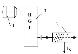
Figure 1-1: Machine parts diagram