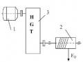
- The starter 1, provides the power source for the machine to operate. The starter can be an electric motor, internal combustion engine, crank, or pedal. This is an indispensable part of a machine.
- Working part 2, is the part that performs the specified function of the machine, different machines will have different working parts. For example: plow blade in plow, grinding wheel shaft in grinder, main shaft and tool table in lathe. Different machines have different working parts. This is also an indispensable part of a machine.
- Transmission part 3, is the part connecting the starter and the drive part.
working part. The transmission part has the task of changing the speed of movement, changing the law of movement, changing the direction of movement or ensuring a certain distance between the driving part and the working part. For example: belt drive, chain drive, gearbox.
In some simple machines there may be no drive train.
Maybe you are interested!
-
 Machine part principle 2 - 1
 -
 Car body electrical practice - 8
zt2i3t4l5ee
zt2a3gs
zt2a3ge
zc2o3n4t5e6n7ts
If the voltage is out of specification, replace the wire or connector.
If the voltage is within specification, install the front fog light relay and follow step 5.
Step 5 Check the front fog light switch
- Remove the D4 connector of the fog light switch
- Use a multimeter to measure the resistance of the front fog light switch.
Measurement location
Condition
Standard
D4-3 (BFG) -D4-4 (LFG)
Light switchFront Fog OFF
>10kΩ
D4-3 (BFG) -D4-4 (LFG)
Front fog light switchON
<1 Ω
- Standard resistor
D4 connector is located on the combination switch assembly.
If the resistance is out of specification, replace the combination switch (the fog light switch is located in the combination switch).
If the resistance is within specification, follow step 6.
Step 6 Check wiring and connectors (front fog light relay-light selector switch)
- Disconnect connector D4 of the combination switch assembly
- Use a voltmeter to measure the voltage value of jack D4 on the wire side.
Measurement location
Control modecontrol
Standard
D4-3 (BFG) - (-) AQ
TAIL
11 to 14 V
D4 connector for the wiring of the combination switch assembly
If the voltage does not meet the standard, replace the wire or connector.
If the voltage is within standard, there may have been an error in the previous measurements.
Step 7 Check the front fog lights
- Remove the front fog light electrical connector.
- Supply battery voltage to the fog lamp terminals
Jack 8, B9 of front fog lamp on the electrical side
blind first.
Power supply location
Terms and Conditions
Battery positive terminal - Terminal 2Battery negative terminal - Terminal 1
Fog lightsbefore morning
- If the light does not come on, replace the bulb.
If the light is on, re-plug the jack and continue to step 8.
Step 8 Check wiring and connectors (relay and front fog lights)
- Disconnect the B8 and B9 connectors of the front fog lights.
- Use a voltmeter to measure voltage at the following locations:
Measurement location
Switch location
Terms and Conditions
B8-2 - (-) AQ
Electric lock ON TAIL size switchFog switch ON
11 to 14 V
B9-2 - (-) AQ
Electric lock ONTAIL size switch Fog switch ON
11 to 14 V
B8 and B9 connectors on the front fog lamp wiring side
Voltage is not up to standard, repair or replace the jack. If up to standard, there may have been an error in the measurement process.
2.2.4. Procedure for removing, installing and adjusting fog lights 1. Procedure for removing
- Remove the front inner ear pads
Use a screwdriver to remove the 3 screws and remove the front part of the front inner ear liner
-Remove the fog light assembly
+ Disconnect the connector.
+ Use a screwdriver to remove 3 screws to remove the fog light cover
2. Installation sequence
-Rotate the fog lamp bulb in the direction indicated by the arrow as shown in the figure and remove the fog lamp from the fog lamp assembly.
-Rotate the fog light bulb in the direction indicated by the arrow as shown in the figure and install the light into the fog light assembly.
- Use a screwdriver to install the fog light cover
-Install the electrical connector
Attention: Be careful not to damage the plastic thread on the lamp assembly.
- Install the front inner ear pads
Use a screwdriver to install the front inner bumper with 3 screws.
3. Prepare the vehicle to adjust the fog light convergence. Prepare the vehicle:
- Make sure there is no damage or deformation to the vehicle body around the fog lights.
- Add fuel to the fuel tank
- Add oil to standard level.
- Add engine coolant to standard level.
- Inflate the tire to standard pressure.
- Place spare tire, tools and jack in original design position
- Do not leave any load in the luggage compartment.
- Let a person weighing about 75 kg sit in the driver's seat.
4. Prepare to check the fog light convergence
a/ Prepare the vehicle status as follows:
- Place the car in a dark enough place to see the lines. The lines are the dividing line, below which the light from the fog lights can be seen but above which it cannot.
- Place the car perpendicular to the wall.
- Keep a distance of 7.62 m between the center of the fog lamp and the wall.
- Park the car on level ground.
- Press the car down a few times to stabilize the suspension.
Note: A distance of approximately 7.62 m is required between the vehicle (fog lamp center) and the wall to adjust the convergence correctly. If the distance of 7.62 m cannot be achieved, set the correct distance of 3 m to check and adjust the fog lamp convergence. (Since the target area varies with the distance, please follow the instructions as shown in the figure.)
b/ Prepare a piece of thick white paper about 2 m high and 4 m wide to use as a screen.
c/ Draw a vertical line through the center of the screen (line V).
d/ Set the screen as shown in the picture. Note:
- Keep the screen perpendicular to the ground.
- Align the V line on the screen with the center of the vehicle.
e/Draw the reference lines (H, V LH and V RH lines) on the screen as shown in the figure.HINT:
Mark the center of the fog lamp on the screen. If the center mark cannot be seen on the fog lamp, use the center of the fog lamp or the manufacturer's name mark on the fog lamp as the center mark.
H line (fog light height):
Draw a line across the screen so that it passes through the center mark. Line H should be at the same height as the center mark of the fog light bulb.
Line V LH, V RH (center mark position of left fog lamp LH and right fog lamp RH):
Draw two lines so that they intersect line H at the center marks.
5. Check the fog light convergence
a/ Cover the fog lamp or remove the connector of the other side fog lamp to prevent light from the unchecked fog lamp from affecting the fog lamp convergence test.
b/ Start the engine.
c/ Turn on the fog lights and make sure that the dividing line is outside the standard area as shown in the drawing.
6. Adjust the fog light convergence
Use a screwdriver to adjust the fog light to the standard area by turning the toe adjustment screw.
Note: If the screw is adjusted too far, loosen it and then tighten it again, so that the last rotation of the light adjustment screw is clockwise.
3. Self-study questions
1. Describe the operating principle of the lighting system with automatic headlight function
2. Describe the operating principle of the lighting system with the function of rotating headlights when turning
3. Draw diagram and connect lighting system on Hyundai Porter car
4. Draw diagram and connect lighting system on Honda Accord 1992
5. Draw the lighting circuit on a 1993 Toyota Lexus
LESSON 3 MAINTENANCE AND REPAIR OF SIGNAL SYSTEM
I. IMPLEMENTATION GOAL
After completing this lesson, students will be able to:
- Distinguish between types of signals on cars
- Correctly describe common symptoms and suspected areas causing damage.
- Connecting signal circuits ensures technical requirements
- Disassemble, install, check, maintain and repair the signal system to ensure technical requirements.
- Ensure safety in work and industrial hygiene
II. LESSON CONTENT
1. General description
The signal system equipped on cars aims to create signals to notify other vehicles participating in traffic about the vehicle's operating status such as: stopping, parking, braking, reversing, turning...
Signals are used either by light such as headlamps, brake lights, turn signals….. or by sound such as horns, reverse music….
Just like the lighting system. A signal system circuit usually consists of: battery, fuse, wire, relay, electrical load and control switch. Only some switches of the signal system are on the combination switch. The switches of other signals are usually located in different locations such as in the gearbox or brake pedal……
2. Maintenance and repair
2.1. Turn signals and hazard lights
The installation location of the turn signal is shown in Figure 3.1. The turn signal control switch is located in the combination switch under the steering wheel. Turning this switch to the right or left will make the turn signal turn right or left.
The hazard light switch is used when the vehicle has a problem while participating in traffic. When the hazard light switch is turned on, all the turn signals on the vehicle will light up at a certain frequency. The hazard light switch is usually placed separately from the turn signal switch (some old cars integrate the hazard and turn signal switches on the same combination switch cluster).
Figure 3.1 Turn signal switch Figure 3.2 Hazard switch
The part that generates the flashing frequency for the lights is called a turn signal relay. The turn signal relay usually has 3 terminals: B (positive power supply); E (negative power supply); L (providing the turn signal switch to distribute to the
lamp)
2.1.1. Circuit diagram
To generate the frequency for the turn signal, a turn signal relay is used in the turn signal circuit. The current from the turn signal relay will be sent to the turn signal switch assembly to distribute the current to the turn signal lights for the driver's purpose.
Figure 3.3. Schematic diagram of a turn signal circuit without a hazard switch
1. Battery; 2. Electric lock; 3. Turn signal relay; 4. Turn signal switch; 5. Turn signal lamp; 6. Turn signal lamp; 7. Hazard switch
Figure 3.4 Schematic diagram of turn signal circuit with hazard switch
1. Battery; 2. Combination switch cluster; 3. Turn signal;
4. Turn signal light; 5. Turn signal relay
Today's cars no longer use three-pin turn signal relays (B, L, E) but use eight-pin turn signal relays (figure 3.5) (pin number 8 is used for hazard lights).
For this type, the current supplying the turn signal lights is supplied directly from the turn signal relay to the lights.
div.maincontent .p { color: black; font-family:"Times New Roman", serif; font-style: normal; font-weight: normal; text-decoration: none; font-size: 14pt; margin:0pt; } div.maincontent p { color: black; font-family:"Times New Roman", serif; font-style: normal; font-weight: normal; text-decoration: none; font-size: 14pt; margin:0pt; } div.maincontent .s1 { color: black; font-family:"Times New Roman", serif; font-style: normal; font-weight: normal; text-decoration: none; font-size: 13pt; } div.maincontent .s2 { color: black; font-family:"Times New Roman", serif; font-style: italic; font-weight: normal; text-decoration: none; font-size: 14pt; } div.maincontent .s3 { color: black; font-family:"Times New Roman", serif; font-style: normal; font-weight: normal; text-decoration: none; font-size: 14pt; } div.maincontent .s4 { color: black; font-family:"Times New Roman", serif; font-style: normal; font-weight: normal; text-decoration: none; font-size: 13pt; } div.maincontent .s5 { color: black; font-family:"Times New Roman", serif; font-style: normal; font-weight: normal; text-decoration: none; font-size: 13pt; vertical-align: 1pt; } div.maincontent .s6 { color: black; font-family:"Times New Roman", serif; font-style: normal; font-weight: normal; text-decoration: none; font-size: 11pt; } div.maincontent .s7 { color: black; font-family:"Times New Roman", serif; font-style: normal; font-weight: normal; text-decoration: none; font-size: 14pt; vertical-align: -9pt; } div.maincontent .s8 { color: black; font-family:"Times New Roman", serif; font-style: normal; font-weight: normal; text-decoration: none; font-size: 11pt; } div.maincontent .s9 { color: #008000; font-family:"Times New Roman", serif; font-style: normal; font-weight: normal; text-decoration: none; font-size: 14pt; } div.maincontent .s10 { color: black; font-family:"Times New Roman", serif; font-style: italic; font-weight: normal; te
Car body electrical practice - 8
zt2i3t4l5ee
zt2a3gs
zt2a3ge
zc2o3n4t5e6n7ts
If the voltage is out of specification, replace the wire or connector.
If the voltage is within specification, install the front fog light relay and follow step 5.
Step 5 Check the front fog light switch
- Remove the D4 connector of the fog light switch
- Use a multimeter to measure the resistance of the front fog light switch.
Measurement location
Condition
Standard
D4-3 (BFG) -D4-4 (LFG)
Light switchFront Fog OFF
>10kΩ
D4-3 (BFG) -D4-4 (LFG)
Front fog light switchON
<1 Ω
- Standard resistor
D4 connector is located on the combination switch assembly.
If the resistance is out of specification, replace the combination switch (the fog light switch is located in the combination switch).
If the resistance is within specification, follow step 6.
Step 6 Check wiring and connectors (front fog light relay-light selector switch)
- Disconnect connector D4 of the combination switch assembly
- Use a voltmeter to measure the voltage value of jack D4 on the wire side.
Measurement location
Control modecontrol
Standard
D4-3 (BFG) - (-) AQ
TAIL
11 to 14 V
D4 connector for the wiring of the combination switch assembly
If the voltage does not meet the standard, replace the wire or connector.
If the voltage is within standard, there may have been an error in the previous measurements.
Step 7 Check the front fog lights
- Remove the front fog light electrical connector.
- Supply battery voltage to the fog lamp terminals
Jack 8, B9 of front fog lamp on the electrical side
blind first.
Power supply location
Terms and Conditions
Battery positive terminal - Terminal 2Battery negative terminal - Terminal 1
Fog lightsbefore morning
- If the light does not come on, replace the bulb.
If the light is on, re-plug the jack and continue to step 8.
Step 8 Check wiring and connectors (relay and front fog lights)
- Disconnect the B8 and B9 connectors of the front fog lights.
- Use a voltmeter to measure voltage at the following locations:
Measurement location
Switch location
Terms and Conditions
B8-2 - (-) AQ
Electric lock ON TAIL size switchFog switch ON
11 to 14 V
B9-2 - (-) AQ
Electric lock ONTAIL size switch Fog switch ON
11 to 14 V
B8 and B9 connectors on the front fog lamp wiring side
Voltage is not up to standard, repair or replace the jack. If up to standard, there may have been an error in the measurement process.
2.2.4. Procedure for removing, installing and adjusting fog lights 1. Procedure for removing
- Remove the front inner ear pads
Use a screwdriver to remove the 3 screws and remove the front part of the front inner ear liner
-Remove the fog light assembly
+ Disconnect the connector.
+ Use a screwdriver to remove 3 screws to remove the fog light cover
2. Installation sequence
-Rotate the fog lamp bulb in the direction indicated by the arrow as shown in the figure and remove the fog lamp from the fog lamp assembly.
-Rotate the fog light bulb in the direction indicated by the arrow as shown in the figure and install the light into the fog light assembly.
- Use a screwdriver to install the fog light cover
-Install the electrical connector
Attention: Be careful not to damage the plastic thread on the lamp assembly.
- Install the front inner ear pads
Use a screwdriver to install the front inner bumper with 3 screws.
3. Prepare the vehicle to adjust the fog light convergence. Prepare the vehicle:
- Make sure there is no damage or deformation to the vehicle body around the fog lights.
- Add fuel to the fuel tank
- Add oil to standard level.
- Add engine coolant to standard level.
- Inflate the tire to standard pressure.
- Place spare tire, tools and jack in original design position
- Do not leave any load in the luggage compartment.
- Let a person weighing about 75 kg sit in the driver's seat.
4. Prepare to check the fog light convergence
a/ Prepare the vehicle status as follows:
- Place the car in a dark enough place to see the lines. The lines are the dividing line, below which the light from the fog lights can be seen but above which it cannot.
- Place the car perpendicular to the wall.
- Keep a distance of 7.62 m between the center of the fog lamp and the wall.
- Park the car on level ground.
- Press the car down a few times to stabilize the suspension.
Note: A distance of approximately 7.62 m is required between the vehicle (fog lamp center) and the wall to adjust the convergence correctly. If the distance of 7.62 m cannot be achieved, set the correct distance of 3 m to check and adjust the fog lamp convergence. (Since the target area varies with the distance, please follow the instructions as shown in the figure.)
b/ Prepare a piece of thick white paper about 2 m high and 4 m wide to use as a screen.
c/ Draw a vertical line through the center of the screen (line V).
d/ Set the screen as shown in the picture. Note:
- Keep the screen perpendicular to the ground.
- Align the V line on the screen with the center of the vehicle.
e/Draw the reference lines (H, V LH and V RH lines) on the screen as shown in the figure.HINT:
Mark the center of the fog lamp on the screen. If the center mark cannot be seen on the fog lamp, use the center of the fog lamp or the manufacturer's name mark on the fog lamp as the center mark.
H line (fog light height):
Draw a line across the screen so that it passes through the center mark. Line H should be at the same height as the center mark of the fog light bulb.
Line V LH, V RH (center mark position of left fog lamp LH and right fog lamp RH):
Draw two lines so that they intersect line H at the center marks.
5. Check the fog light convergence
a/ Cover the fog lamp or remove the connector of the other side fog lamp to prevent light from the unchecked fog lamp from affecting the fog lamp convergence test.
b/ Start the engine.
c/ Turn on the fog lights and make sure that the dividing line is outside the standard area as shown in the drawing.
6. Adjust the fog light convergence
Use a screwdriver to adjust the fog light to the standard area by turning the toe adjustment screw.
Note: If the screw is adjusted too far, loosen it and then tighten it again, so that the last rotation of the light adjustment screw is clockwise.
3. Self-study questions
1. Describe the operating principle of the lighting system with automatic headlight function
2. Describe the operating principle of the lighting system with the function of rotating headlights when turning
3. Draw diagram and connect lighting system on Hyundai Porter car
4. Draw diagram and connect lighting system on Honda Accord 1992
5. Draw the lighting circuit on a 1993 Toyota Lexus
LESSON 3 MAINTENANCE AND REPAIR OF SIGNAL SYSTEM
I. IMPLEMENTATION GOAL
After completing this lesson, students will be able to:
- Distinguish between types of signals on cars
- Correctly describe common symptoms and suspected areas causing damage.
- Connecting signal circuits ensures technical requirements
- Disassemble, install, check, maintain and repair the signal system to ensure technical requirements.
- Ensure safety in work and industrial hygiene
II. LESSON CONTENT
1. General description
The signal system equipped on cars aims to create signals to notify other vehicles participating in traffic about the vehicle's operating status such as: stopping, parking, braking, reversing, turning...
Signals are used either by light such as headlamps, brake lights, turn signals….. or by sound such as horns, reverse music….
Just like the lighting system. A signal system circuit usually consists of: battery, fuse, wire, relay, electrical load and control switch. Only some switches of the signal system are on the combination switch. The switches of other signals are usually located in different locations such as in the gearbox or brake pedal……
2. Maintenance and repair
2.1. Turn signals and hazard lights
The installation location of the turn signal is shown in Figure 3.1. The turn signal control switch is located in the combination switch under the steering wheel. Turning this switch to the right or left will make the turn signal turn right or left.
The hazard light switch is used when the vehicle has a problem while participating in traffic. When the hazard light switch is turned on, all the turn signals on the vehicle will light up at a certain frequency. The hazard light switch is usually placed separately from the turn signal switch (some old cars integrate the hazard and turn signal switches on the same combination switch cluster).
Figure 3.1 Turn signal switch Figure 3.2 Hazard switch
The part that generates the flashing frequency for the lights is called a turn signal relay. The turn signal relay usually has 3 terminals: B (positive power supply); E (negative power supply); L (providing the turn signal switch to distribute to the
lamp)
2.1.1. Circuit diagram
To generate the frequency for the turn signal, a turn signal relay is used in the turn signal circuit. The current from the turn signal relay will be sent to the turn signal switch assembly to distribute the current to the turn signal lights for the driver's purpose.
Figure 3.3. Schematic diagram of a turn signal circuit without a hazard switch
1. Battery; 2. Electric lock; 3. Turn signal relay; 4. Turn signal switch; 5. Turn signal lamp; 6. Turn signal lamp; 7. Hazard switch
Figure 3.4 Schematic diagram of turn signal circuit with hazard switch
1. Battery; 2. Combination switch cluster; 3. Turn signal;
4. Turn signal light; 5. Turn signal relay
Today's cars no longer use three-pin turn signal relays (B, L, E) but use eight-pin turn signal relays (figure 3.5) (pin number 8 is used for hazard lights).
For this type, the current supplying the turn signal lights is supplied directly from the turn signal relay to the lights.
div.maincontent .p { color: black; font-family:"Times New Roman", serif; font-style: normal; font-weight: normal; text-decoration: none; font-size: 14pt; margin:0pt; } div.maincontent p { color: black; font-family:"Times New Roman", serif; font-style: normal; font-weight: normal; text-decoration: none; font-size: 14pt; margin:0pt; } div.maincontent .s1 { color: black; font-family:"Times New Roman", serif; font-style: normal; font-weight: normal; text-decoration: none; font-size: 13pt; } div.maincontent .s2 { color: black; font-family:"Times New Roman", serif; font-style: italic; font-weight: normal; text-decoration: none; font-size: 14pt; } div.maincontent .s3 { color: black; font-family:"Times New Roman", serif; font-style: normal; font-weight: normal; text-decoration: none; font-size: 14pt; } div.maincontent .s4 { color: black; font-family:"Times New Roman", serif; font-style: normal; font-weight: normal; text-decoration: none; font-size: 13pt; } div.maincontent .s5 { color: black; font-family:"Times New Roman", serif; font-style: normal; font-weight: normal; text-decoration: none; font-size: 13pt; vertical-align: 1pt; } div.maincontent .s6 { color: black; font-family:"Times New Roman", serif; font-style: normal; font-weight: normal; text-decoration: none; font-size: 11pt; } div.maincontent .s7 { color: black; font-family:"Times New Roman", serif; font-style: normal; font-weight: normal; text-decoration: none; font-size: 14pt; vertical-align: -9pt; } div.maincontent .s8 { color: black; font-family:"Times New Roman", serif; font-style: normal; font-weight: normal; text-decoration: none; font-size: 11pt; } div.maincontent .s9 { color: #008000; font-family:"Times New Roman", serif; font-style: normal; font-weight: normal; text-decoration: none; font-size: 14pt; } div.maincontent .s10 { color: black; font-family:"Times New Roman", serif; font-style: italic; font-weight: normal; te -
 Basic electronic engineering - City College of Construction. HCM Part 1 - 1
 -
 Business Communication and Negotiation Part 2 - 12
 -
 Office 2013 Basic Part 2 - 1
c. Machine details
When we disassemble a machine, a machine part will receive small elements of the machine, for example: bolts, nuts, gears, shafts. If we continue to separate these elements, it will no longer be useful. Small elements of the machine are called machine parts.
Can be defined as follows: Machine parts are the first basic elements that make up a machine, have a definite shape and size, and have a certain function in the machine.
Machine parts can be divided into 2 groups:
- Group of machine parts with common uses. Including machine parts used in many different types of machines. In different types of machines, machine parts have the same shape and use. For example: gears, joints, shafts, bolts, bearings.
- Group of machine parts with specific uses . Including machine parts that are only used for
used in a certain type of machine. In different types of machines, the shape or function of machine parts is different. For example: crankshaft, turbine, gearbox housing, engine block.
In the lecture Principles - Machine Details 2, we only study the details.
general purpose machine
1.1.2. Main requirements for machines and machine parts
Before studying machine design and machine parts, we need to know what a good machine is. To do that, we need to know the parameters to evaluate the quality of the machine, or the main requirements for the machine and machine parts.
A machine or machine part design is called reasonable when the machine satisfies the following 6 main requirements:
- The machine has high efficiency, shown in:
+ Consumes little energy for a product processed on the machine,
+ High processing productivity,
+ High precision of machined products,
+ Low cost of using the machine,
+ Reasonable size and weight of the machine.
- The machine has high working capacity: the machine completes its intended function well under the working conditions of the production facility, is always durable and hard enough, can withstand the temperature and humidity of the environment, and is not subject to excessive vibration.
- The machine has high reliability: the machine always works well, ensuring technical standards.
technical design. During the time of use, the machine rarely breaks down, the time and cost for repair is low.
- Safe to use: does not cause danger to users, machines, and equipment.
other machine parts, when the machine is working normally and even when the machine has a problem.
- The machine has high technology, shown in:
+ The structure of the machine must be suitable for production conditions and scale.
+ The structure of machine parts is simple and reasonable,
+ Correct accuracy and roughness level selected,
+ Choose the appropriate method of making blanks .
- The machine is highly economical, shown in:
+ The effort and cost for design is minimal,
+ Materials for manufacturing machine parts are cheap and easy to supply.
+ Easy to process, manufacturing cost is the least,
+ The price of the machine is the lowest.
1.1.3. Steps to design a machine
Before starting to design a machine, we must master the design task,
need to know the following figures:
- Number of machines to be manufactured. How many to manufacture?
- Machined products. Shape , size, material, accuracy?
- Machine productivity . How many products need to be processed in 1 hour?
- Machine life, or how long does it take to use the machine until it is discarded?
- Requirements for machine size and weight?
- What are the characteristics of the environment in which the machine will work?
- Other requirements?
The design work is carried out in 7 steps:
1. Determine the operating principle and working mode of the machine. It is advisable to refer to existing machines to select the appropriate operating principle. The working mode of the machine and the machine structure are related to the selection of the values of the calculation coefficients during the determination process.
size of machine part
2. Make a general diagram of the whole machine and diagrams of machine parts. The diagram must satisfy the requirements of the design task. It is necessary to make several machine diagram options, then compare and choose the best option.
3. Determine the load acting on the machine, machine parts and each machine detail. This is an important step. If the load is not determined correctly, we will design a machine that is either not durable enough or not economically viable.
4. Calculate and design machine parts. Determine shape, size, and draw.
structure of each machine part
5. Establish technological process for processing each machine part.
6. Establish the process of assembling machine parts and assembling the whole machine.
7. Create design documents for the machine. Create drawings, descriptions, and instruction documents.
use and repair machine.
1.1.4. Steps to design a machine part
To carry out the fourth step in the machine design process, we must calculate the design of each machine part in turn. Before carrying out the design of the machine part, it is necessary to know the data related to the machine part:
- Loads acting on machine parts: intensity, direction, direction, point of application and its characteristics.
- The life of the machine part. Normally the life of the machine part is equal to the age of the machine.
The life of the machine, in some cases only a fraction of the life of the machine.
- Working conditions of machine parts.
- Requirements on materials, weight , size.
- Machining capabilities of the mechanical facility that will manufacture the machine parts.
Designing a machine part usually proceeds through 7 steps:
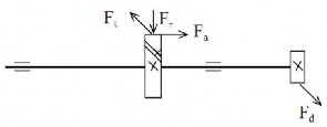
Figure 1-2: Axis calculation diagram
1. Create detailed machine calculation diagram - diagram the structure of machine parts.
2. Place loads on the detailed machine calculation diagram (Figure 1-2).
3. Select materials for manufacturing machine parts.
4. Calculate the main dimensions of machine parts according to durability conditions or load conditions.
hard case
5. Select other dimensions and draw the structure of the machine part.
6. Test machine parts for durability, hardness, heat resistance, and knife resistance.
If not guaranteed, the size must be increased, if too much, the size of the machine part must be reduced.
7. Make detailed manufacturing drawings of machine parts. They fully show the shape, size, tolerance, surface quality, materials, heat treatment methods, and technical requirements for processing and assembly.
1.2. Overview of requirements for machines and machine parts
When determining the dimensions of machine parts, we need to pay attention to the following points:
- The load acting on machine parts is very complex and difficult to determine accurately, so we only determine the main load components, the secondary components are considered by an adjustment coefficient, called the load coefficient.
- Formulas used in calculating machine part design have 3 types: formulas
exact formula, approximate formula, and empirical formula.
+ Precise formula, built on the basis of Mathematics and Physics theory. Using precise formula, in all cases we always get correct results. In the field of machine part design, this type of formula is very rare.
+ Approximate formulas are built on the basis of having to make assumptions. For example : assuming the material is homogeneous, isotropic , or absolutely rigid. Calculation results, when using approximate formulas, are considered accurate when the conditions of the problem coincide with the assumptions. The further the conditions of the design problem are from the assumptions, the less reliable the calculation results are. In approximate formulas, people put in coefficients to adjust the accuracy of the calculation results, taking into account the deviation between the actual conditions of the problem and the assumed conditions. When designing, we must choose reasonable values for the coefficients. This type of formula is very popular in the field of machine part design.
+ Empirical formulas, or empirical formulas, are built on the basis of statistics of results obtained from experiments, or from experience in using machines. Design calculation results using empirical formulas are only accepted when the conditions of the problem coincide with experimental conditions, or coincide with experience in use. In conditions other than experiments and experience, they cannot be used .
- There are dimensions of machine parts that can be determined accurately through only one calculation. There are also dimensions that must go through two or more calculation steps to get the correct result, because there is not enough data to calculate accurately right away.
- A machine part usually has many dimensions, only the dimensions of the main sections should be calculated (including sections involved in assembly, sections with high stress values, sections that often have damage). The remaining dimensions will be selected during the process of drawing the structure of the machine part. Select according to the assembly conditions with the parts.
other details, according to the rationality, aesthetics of the structure, or according to the experience of the person
design .
- In each step of calculating the machine part design, there may be many options that satisfy the requirements of the problem, we should analyze and choose 2 to 3 most reasonable options to continue calculating. In the final step, we need to compare and choose the best option as the design result.
- Currently, there are many computer programs (application software) used to calculate and automatically draw machine parts, machine components, and even machines. When using them, we need to choose the appropriate software for the design problem, and must have a firm grasp of machine part design knowledge to effectively use the above application software.
1.3. Loads and stresses
1.3.1. Loads acting on machines and machine parts
Loads acting on machines and machine parts include force, moment and pressure. Load is a vector quantity, determined by the parameters: intensity, direction, direction, point of application and characteristics of the load. In which:
- Force , symbolized by the letter F, unit of measurement is N, 1 N = 1 kg.m/s.
- Bending moment, symbol is M, unit of measurement is Nmm.
- Torque, symbol is T, unit of measurement is Nmm.
- Pressure, symbol is p, unit of measurement is MPa, 1 MPa = 1 N/mm 2 .
Classification of loads. Let's get acquainted with some names of loads, and their characteristics:
- Constant load is a load whose direction, direction, and intensity do not change.
over time. The diagram of the constant load is shown above ( Figure 1-3).
- Variable load is a load in which at least one of the three quantities (direction, direction , intensity) changes over time. In actual machine part calculations, it is common to encounter loads with variable intensity; the diagram of the variable load is shown above (Figure 1-4).
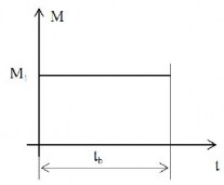
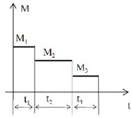
Figure 1-3: Constant load Figure 1-4 : Variable load
- Equivalent load, is the conventional constant load, equivalent to the regime
The variable load acting on the machine part. In other words: when calculating the machine part subjected to variable load, we must use a constant load mode equivalent to the variable load mode in terms of strength and service life of the machine part.
- Fixed load is a load whose set point does not change during the operation of the machine part.
- Moving load, is a load whose application point moves on the machine part, when the machine
work.
- Nominal load is the load acting on the machine part in theory.
- Calculated load . When working , a machine part, or a part of a machine part , must bear a load greater than the nominal load. The additional load can be caused by vibration , or by a load concentrated on a part of the machine part. The machine part must be designed so that the part that bears the large load does not become weak.
So we have to calculate the machine details according to the load greater than the nominal load, this load is called calculated load.
1.3.2. Stress
Stress is the force that appears in the elements of a machine part when the machine part is subjected to a load.
Stress is a vector quantity, it is determined by direction, direction, and intensity.
The unit of measurement of stress is MPa, 1MPa = 1N/mm 2 .
Stress is divided into two groups:
- The symbol for normal stress is . The direction of normal stress coincides with the direction of the method.
The line of the element is separated from the machine part.
- Shear stress is denoted by . Shear stress has direction parallel to the plane of the segment
elements are separated from machine parts.
Corresponding to the applied loads, stress is divided into the following types:
- Tensile stress, denoted by σ k ,
- Compressive stress, denoted by σ n ,
- Bending stress, denoted by σ u ,
- Contact stress, denoted by σ tx , or σ H ,
- Stamping stress, denoted by σ d ,
- Torsional stress, denoted by τ x ,
- Shear stress, denoted by τ c .
In addition, stress is also divided into constant stress and changing stress :
- Constant stress, also known as static stress, is stress whose direction, magnitude, and intensity do not change over time. The diagram of static stress is shown above (Figure 1-5).
- Changing stress is stress that has at least one quantity (direction, direction, intensity ) changing over time. Stress can change randomly, or change periodically. In calculating machine part design, we often encounter the type of stress that changes periodically, or almost periodically. The diagram of cyclic stress change is shown above (Figure 1-6).
A stress cycle is defined by the parameters:
- Maximum stress σ max ,
A stress cycle is defined by the parameters:
- Maximum stress σ min ,
- Average stress σ m ; σ m = (σ max + σ min ) / 2,
- Stress amplitude σ a ; σ a = (σ max - σ min )/2,
- Stress cycle factor r; r = σ max / σ min , or r = σ min / σ max , when σ min = 0.
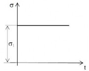
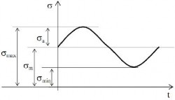
Figure 1-5. Static stress diagram Figure 1-6. Changing stress diagram
Based on the value of the stress cycle coefficient r, stress is divided into the following types:
- Stress changes cyclically, when the stress cycle has r ≥ 0.
- Stress changes symmetrically when the stress cycle has r < 0.
- Static stress is a special case of changing stress, with r = 1.
With the same stress value, but different r, the ability of the stress to destroy the material is also different. Machine parts subjected to static stress have a longer life than machine parts subjected to dynamic changing stress, machine parts subjected to symmetrically changing stress have the lowest life.
1.4. Fatigue resistance of machine parts
1.4.1. Fatigue failure
When a machine part is subjected to static stress and is damaged , it is called static stress failure . In other words, the machine part does not have enough static strength. Calculating the machine part to prevent this type of failure is called static strength calculation.
When a machine part is damaged by changing stress, it is called fatigue failure, or the machine part does not have enough fatigue strength. Calculating the machine part to prevent this type of failure is called fatigue calculation.
When the static stress exceeds the limit stress value, the machine part is suddenly damaged.
The fracture is rough and new, and under microscope observation shows leakage of metal grain structure (Figure 1-7).
Figure 1-7: Fracture due to insufficient
static resistance
Figure 1-8: Fracture due to insufficient
fatigue strength
Fatigue failure occurs slowly, in the following sequence:
- After a certain number of stress cycles, small cracks will appear at places where stress is concentrated on the machine part.
- This crack grows larger and larger, gradually reducing the load-bearing cross-sectional area of the
machine parts, thereby increasing the stress value.
- Until the machine part no longer has enough static strength, it is damaged.
Observation of the fracture shows that the machine part is damaged due to fatigue (old surface is smooth) and the machine part is damaged due to insufficient static strength (new surface is rough) (Figure 1-8).
A machine part will be damaged by fatigue when the stress generated in the machine part (σ, τ) is greater than the allowable stress ([σ], [τ]). The value of the allowable stress chosen depends not only on the mechanical properties of the material used to make the machine part, but also on the number of cycles required to operate the machine part . The fewer the number of cycles required to operate, the higher the value of the allowable stress that can be chosen.
Experiments were conducted to determine the relationship between the stress value and the number of operating cycles until failure of the machine part, shown in Figure 1-9. This is the fatigue curve of the machine part in the Cartesian coordinate system ONσ.
In there:
NO : is the basic cycle number .
σ r : fatigue limit of the material. m: exponential of the fatigue curve. σ N : short-term fatigue limit:
σ N = K N σ r .
K N : short-term fatigue limit increase factor:
m
N 0
N
K N