CHAPTER 2
MAIN PERFORMANCE INDICATORS OF MACHINE PARTS
2.1. Durability
2.1.1. Durability requirements
Maybe you are interested!
-

 Applying MIKE 11 model to determine minimum flow on the main stream of Vu Gia - Thu Bon river and proposing maintenance solutions - 13
 -
 Machine part principle 2 - 1
 -
 Steps to Determine the Competitiveness of a Business
 -
 Study on the influence of some factors on specific energy cost and surface roughness when milling flat surfaces with face milling cutters on milling machine TUM 20VS - 1
 -
 User Generated Database
Durability is the most important criterion of machine parts. If the machine part is not durable enough , it will be damaged such as: broken, cracked, cut, bent, warped, worn, crushed, pitted surface, etc. At that time, the machine part can no longer continue to work. It loses its ability to work.
A machine part is considered to have sufficient durability when it satisfies the durability conditions.
The stability conditions are written as follows:
σ ≤ [σ]
τ ≤ [τ] S ≥ [S].
In which: σ and τ are the stresses generated in the machine part when under load.
[σ] and [τ] are the allowable stresses of the machine part.
S is the calculated safety factor of the machine part,
[S] is the allowable safety factor of the machine part.
2.1.2. How to determine the stress generated in machine parts
The stress generated in machine parts is determined according to the theory of the subjects Strength of Materials and Elasticity Theory. On that basis, the subject Machine Parts inherits or builds specific stress calculation formulas for each type of machine part.
a. For machine parts subjected to constant loads
In case the machine part has a single stress state (only σ or τ), the
Stress generated in machine parts according to the formula of Strength of Materials.
F
For example , calculate the tensile stress generated in the load-bearing bar F: K A
In case the machine part has complex stress (with both σ and τ), when measuring the stress generated in the machine part, it is taken according to the equivalent stress σ tđ , σ tđ is calculated according to the "Potential energy can change shape" theory of strength - Fourth strength theory:
2 3 2
td
or according to the "Maximum shear stress" theory - Third strength theory:
2 4 2
td
In case the contact area between two surfaces is quite large, the stress generated is
calculated by stamping stress.
If the contact area between two surfaces is very small (initially contact along the line,
or pointwise), the stress generated is the maximum contact stress at the center of the contact area.
contact, calculated by the Hertz formula σ H .
b. For machine parts subject to variable loads
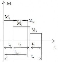
Figure 2-1 Variable load
For example: Consider a machine part working with a changing load mode: during the usage time tb, the machine part works with n load modes, each load mode M i works with time t i ( Figure 2-1).
The stress generated in the machine part will be calculated according to the equivalent constant load mode.
The equivalent load mode is usually selected as follows:
M tđ = M 1 (M 1 is the largest load in the variable load mode).
The equivalent working time t btđ of a machine part is determined based on the principle of " Simple addition of fatigue losses". The equivalent life of a machine part, in most cases, is calculated according to the formula:
n M m
M
t btd i t i
i 1 1
In case of determining the number of contact stress cycles, the tbtđ is calculated
by formula:
n M
m / 2
M
t btd i t i i 1 1
Where m is the power of the fatigue curve.
The stress value is calculated according to the load M tđ , or according to the load M 1 , the number of stress cycles will be calculated according to t btđ .
2.1.3. How to determine allowable stress
- Determine the allowable stress by looking up the table. In the Mechanical Design Handbook, and in the Machine Detail Exercise Book, there are tables recording the allowable stress of some common machine parts. The allowable stress table is established by experiment , or by experience gained during the use of the part.
machine. This method of determination gives fairly accurate results.
- Calculate allowable stress according to the approximate formula:
[σ]= σ lim /S [τ] = τ lim /S,
In which: σ lim and τ lim are the limiting stress. Depending on each specific case, the limiting stress can be the yield limit (σ ch , τ ch ), the tensile limit (σ b , τ b ), the fatigue limit (σ r , τ r ), the short-term fatigue limit (σ rN , τ rN ) of the material used to manufacture the machine part.
S is the safety factor, the S factor is determined from the component safety factors:
S = S 1 .S 2 .S 3
In which: S 1 is the coefficient considering the accuracy in determining load and stress, S 1 can be selected in the range of 1.2 ÷ 1.5.
S 2 is a coefficient that considers the uniformity of mechanical properties of the material. For machine parts
Forged or rolled steel, take S 2 = 1.5, cast iron machine parts can take S 2 = 2 ÷ 2.5.
S 3 is a coefficient considering special safety requirements for important machine parts in the machine, or directly related to labor safety , taking S 3 = 1.2÷1.5.
- Allowable stress can also be calculated by empirical formula.
For example , when calculating friction wheels, the allowable contact stress is taken according to the surface hardness.
surface: [σ H ] = (1.5 ÷ 2.5) HB, or [σ H ] = (13 ÷ 18) HRC.
2.2. Fatigue strength
- When two contact surfaces have pressure p, have relative sliding with each other and have friction, there will always be wear. The greater the pressure, the greater the relative sliding velocity, the greater the coefficient of friction, the faster the wear rate. Between the pressure p and the friction distance s, there is a relationship according to the following formula:
p m s = constant.
The exponent m depends on the coefficient of friction f of the contact surfaces.
The value of m is taken as follows: when there is semi-wet friction (f = 0.01 ÷ 0.09) take m = 3, when there is semi- dry friction (f = 0.1 ÷ 0.3) take m = 2, when there is dry friction or there is abrasive between the two contact surfaces (f = 0.4 ÷ 0.9) take m = 1.
- Wear causes a loss of material on the surface of the part, the shaft size of the machine part decreases, the hole size increases, the gaps increase, reducing the accuracy and reducing the performance of the machine. When the size is reduced too much, it can lead to the machine part not being durable enough. Wear also reduces the surface quality of the machine part, reduces the working capacity of the machine, and accelerates the wear rate.
- Machine parts are considered to have sufficient wear resistance if, during use,
The amount of wear has not exceeded the allowable value.
- To ensure wear resistance , machine parts are calculated according to the following empirical formula:
p ≤ [p] or pv ≤ [pv].
Where p is the pressure on the contact surface, v is the relative sliding velocity between the two
surface
- To improve the wear resistance of machine parts, it is necessary to fully lubricate the contact surface, use materials with low coefficient of friction. Increase the contact surface area to reduce pressure. Choose the shape of the machine part and its movement law reasonably so that the relative sliding velocity is the smallest. Use surface heat treatment measures to increase hardness, increase the allowable pressure of the surface.
- In addition, to avoid electrochemical corrosion , the non-working surfaces of the parts
The machine needs to be protected by coating with anti-rust paint, or by plating.
2.3. Hardness
2.3.1. Hardness requirements
A machine part is considered to be under-rigid when its elastic deformation exceeds the allowable value.
When a machine part is not hard enough, its working accuracy will decrease, often leading to the phenomenon of jamming and not being able to move, or increasing the additional load in the machine part, or affecting the working quality of other machine parts assembled with it.
Hardness is also an important criterion of machine parts. In some cases, machine parts are durable enough but not hard enough, then the size of the machine part must be increased to be hard enough, accepting excess durability.
2.3.2. How to evaluate the hardness index of machine parts
A machine part meets the hardness criteria when it satisfies the following hardness conditions:
∆l ≤ [∆l],
y ≤ [y],
θ ≤ [θ],
φ ≤ [φ],
∆h ≤ [∆h].
In which: ∆ l is the elongation or contraction of the machine part when under load, y is the rotation of the machine part being bent,
θ is the rotation angle of the cross-section of the machine part being bent, φ is the twist angle of the machine part being twisted,
∆ h is the deformation of the contact surface.
[∆l], [y], [θ], [φ] and [ ∆ h] are the allowable values of the strains.
The values of ∆l, y, θ, φ are calculated according to the formula of Strength of Materials.
The ∆ h value of the initial contact object according to the point or line is determined
According to Herzegovina's theory, the contact area of an object is determined by
by experiment
The values of [∆l], [y], [ θ], [φ], [ ∆h] are selected according to the specific working conditions of the
Machine parts can be looked up in Mechanical Design Handbooks or Machine Parts Exercise Books.
To evaluate the ability to resist deformation of machine parts, people also use the stiffness coefficient C, which is the ratio between deformation and the force caused by them. The higher the stiffness coefficient of a machine part, the smaller the ability to deform. The coefficient C is determined according to the formula of Strength of Materials.
To increase the stiffness of machine parts, it is necessary to choose a reasonable cross-sectional shape of the machine part , especially hollow cross-section. If necessary, additional stiffening ribs should be used. For machine parts requiring high stiffness, materials with low mechanical properties should be selected to avoid residual strength.
2.4. Heat resistance
2.4.1. Requirements for heat resistance index
During the machine's operation, the power lost due to friction is converted into heat energy to heat up the machine parts. Working temperature higher than the allowable value can cause the following harmful effects:
+ Reduces the mechanical properties of the material, leading to a reduction in the load-bearing capacity of the component.
machine part
+ Reduces viscosity of oil and lubricating grease, increases abrasion resistance.
+ Machine parts with large thermal deformation change the clearance in the dynamic links, which can lead to jamming or warping.
2.4.2. How to evaluate the heat resistance index of the machine
A machine or machine part is considered to have sufficient heat resistance when it satisfies the following conditions:
Heat resistant:
θ ≤ [θ],
In which: θ is the working temperature of the machine or machine part.
[θ] is the allowable temperature of the machine.
The working temperature θ is determined from the heat balance equation: Ω = Ω 1 + Ω 2
In which: Ω is the heat generated in a unit of time, when the machine
work,
Ω = 860.(1 - η).P (kCal/h)
η: machine performance,
P: working capacity of the machine, kW.
Ω 1 is the heat released into the environment in a unit of time, kCal/h.
Ω 1 = k t .A t .(θ - θ 0 ) (kCal/h)
k t : heat dissipation coefficient to the environment, can be taken as k t = (7.5 ÷ 15) kCal/m 2 h 0 C
A t : heat dissipation area of the machine, in m2, θ 0 : working environment temperature of the machine, 0 C.
Ω 2 is the heat output by the cooling device in one hour, kCal/h.
Instead of the heat balance equation, we have the formula for calculating the working temperature θ as follows:
860(1 ) P 2
k A0
tt
Allowable temperature [θ] can be found in Mechanical Design Handbooks, depending on the type of lubricating oil , material of the machine part and working function of the machine part.
When the machine part does not meet the heat resistance criteria, meaning θ > [θ], it is necessary to find a solution. It is possible to re-select the lubricant to increase the allowable temperature [ θ].
Or reduce the working temperature θ by:
+ Increase the heat dissipation surface area A t by using ribs and heat dissipation fins .
+ Increase the heat dissipation coefficient k t by using a fan or water spray.
+ Use cooling devices .
2.5. Oscillation stability
In the structure of the machine, each machine part is an oscillating system with its own oscillation frequency ω 0 . If the machine part oscillates beyond the allowable level, it will cause vibration, reducing the working accuracy of the machine part and other machine parts. At the same time, it will cause additional load, causing large deformation of the part, which can lead to damage to the machine part. Or cause loud noise, unpleasant noise.
When starting the machine, the machine parts begin to oscillate freely. During operation , if there is no source of oscillation affecting the machine part, the free oscillation of the machine part will gradually die out after a few minutes. If the machine part is subjected to a source of oscillation, it will oscillate forcedly.
The source of vibration is usually rotating machine parts with eccentric mass, machine parts moving back and forth periodically, or transmitted by surrounding machines . The larger the amplitude of the source, the more the machine part oscillates , especially when the frequency of the source is equal to or close to the natural frequency ω 0 , at which time the machine part oscillates very strongly (resonance phenomenon).
A machine part is considered to be oscillating when its oscillation amplitude is less than the allowable amplitude. In practice, it is very difficult to accurately determine the oscillation amplitude of a machine part. Therefore, calculating the oscillation tolerance is replaced by finding measures to limit the oscillation of the machine part.
Measures to limit vibration of machine parts include :
- Eliminate sources of vibration: by balancing the machine, limiting the use of
the laws of reciprocating motion in the machine, isolating the machine from sources of vibration
around.
- Let the machine part work with a number of revolutions far from the critical number of revolutions
(corresponding to the natural frequency ω 0 ) to avoid resonance.
- Change the dynamic properties of the system to change the natural frequency ω 0 .
- Use vibration reduction devices.
Chapter 2 review questions
Sentence 2.1
State the requirements for the durability of machine parts.
Sentence 2.2
State the requirements for fatigue strength of machine parts.
Sentence 2.3
State the requirements for the hardness of machine parts.
Sentence 2.4
State how to evaluate the heat resistance index of the machine.
Sentence 2.5
What is oscillatory stability?