tire bone
For example: A passenger car tire has the symbol 185/70 HR 14
In which: 185 - tire width (mm) 70 - profile index
H - standard car speed corresponding to v = 210 km/h R - tire structure
14 - wheel rim diameter (inches)
2.2. General concepts
2.2.1. Theoretical motion velocity v o :
v o is the velocity of the vehicle when moving completely without slipping.
Here:
v S l o t
2 r b N b
t
b r b
(2-3)
S l – Theoretical distance the wheel has rolled. t – Time the wheel has rolled.
r b – Calculated radius of the wheel. N b – Total number of revolutions of the wheel.
b – Angular velocity of the wheel.
2.2.2. Actual motion velocity v:
v is the vehicle's speed when taking into account the effect of wheel slippage with the road surface.
In there:
v S t
t
2 r l N b
t
b r l
(2-4)
S t – actual distance the wheel has rolled. t – time the wheel has rolled.
r l – rolling radius of the wheel.
2.2.3. Sliding speed
When the vehicle moves, there is a slippage between the wheels and the road surface, the actual speed of the vehicle and the theoretical speed will be different. The difference between the two speeds mentioned above is the slippage speed:
v v v o b r l b r b
2.3. Dynamics of passive wheels
2.3.1. Problem statement
(2-5)
When the car moves, the surface of the tire contacts the road at many points and forms a contact area. Due to the interaction between the wheel and the road surface, at
At the point of contact, partial reactions from the road will act on the wheel and are called road reactions. These reactions are divided into three force components as follows:
- The normal reaction force is the component perpendicular to the road surface, located in the wheel plane, denoted as the resultant force Z.
- Tangential reaction force acts in the plane of the wheel, parallel to the road surface, denoted by P t .
- The horizontal reaction force lies in the plane of the road and is perpendicular to the plane.
flat wheel, symbol is Y.
In addition, the wheel is also subject to the vertical load G b and the thrust force from the chassis acting on the wheel axle, denoted as P x .
Rolling of wheels on the road can be considered in the following cases:
- Case 1: Elastic wheel rolling on hard road (asphalt or concrete road)
- Case 2: Elastic wheel rolling on deformed road (dirt road or sand road).
2.3.2. Dynamics of elastic wheels rolling on rigid roads
2.3.2.1. Tire deformation
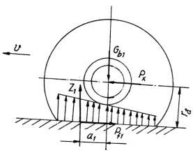
When a car moves, the wheels roll and are subjected to the following forces:
- Vertical load G b1
- The thrust from the chassis acts at the center of the wheel axle P x
- The resultant force of perpendicular reactions
Z 1 , rolling resistance P f1 .
These forces are shown in Figure 2.2. There are also frictional forces and moments.
In wheel bearings, moments of inertia exist but they are of small value and can be ignored in calculations.
Figure 2. 2. Diagram of forces acting on the wheel
elastic car rolling on hard road
In this case, the wheel is deformed, but the hard asphalt road surface is considered not deformed. Therefore, when the wheel rolls, only the tire elements are deformed. The tire elements in the front will enter the contact area and be compressed, the tire elements in the back will exit the contact area and return to their original state. If the tire has ideal elasticity, the energy consumed for the tire deformation will be completely returned when it returns to its original state. However, in reality, the consumed energy is not completely returned, but a part is converted into heat and radiated to the surrounding environment. Thus, resistance to motion will arise.
of a car due to friction between the tire elements (called internal friction) and friction between the tire and the road.
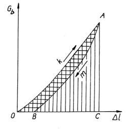
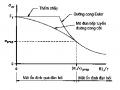
Figure 2.3 shows the variation of deformation in tire elements (Dl) according to the load applied to the wheel (G b ). As the load increases, the deformation of the tire increases, the energy consumed for tire deformation in the compression stage corresponds to the area OAC.
As the load decreases, the tire will spring back, and energy is returned due to the elasticity of the tire corresponding to the BAC area. Thus, the energy is dissipated due to the internal friction of the tire and
The friction between the tire and the road is the difference between the two areas mentioned above (area OAB).
Figure 2. 3. Deformation characteristic graph of elastic wheel
Due to the deformation of the tire elements when entering the contact area, the partial reactions of the road acting on the wheel in the front part of the contact area are larger than those at the rear. Therefore, their resultant force is deflected forward by a distance a 1 compared to the vertical line passing through the center of the wheel axle.
2.3.2.2. Determination of rolling resistance and rolling resistance coefficient
To determine the value of rolling resistance (the resultant of the tangential reactions) and the rolling resistance coefficient, we establish the moment balance equation of all forces about the wheel axle center:
Z 1 .a 1 - P f1 .r đ = 0 Z 1 .a 1 = P f1 .r đ
Which Z 1 .a 1 = G b1 .a 1 = P x .r d (2-6)
From the above formula we derive the formula for calculating rolling resistance as follows:
P f1 = Z 1 a 1 = G b1 a 1 (2-7)
r d r d
In which: r - dynamic radius of the wheel
a 1 - distance from the point of application of the resultant force Z 1 to the intersection of the perpendicular line passing through the center of the wheel axle with the line
If we denote f 1 =
a 1 (2-8)
r d
then we have: P f1 = f 1 .G b1 = f 1 .Z 1
The coefficient f 1 is called the rolling resistance coefficient. Thus, the rolling resistance force is equal to the vertical load acting on the wheel multiplied by the rolling resistance coefficient.
Rolling resistance moment: M f = P f1 .r đ (2-9)
Comment:
Factors affecting rolling resistance and rolling resistance moment are:
* Vertical load acting on the wheel
* Tire manufacturing materials
* Air pressure in tires
* Physical properties of sugar.
2.3.3. Dynamics of elastic wheel rolling on deformable road
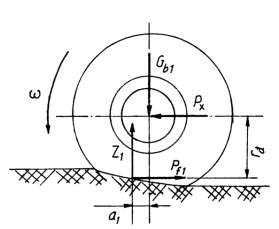
When the wheel rolls, both the wheel and the road deform, but the deformation of the road is smaller than the deformation of the tire.
Figure 2.4 is a diagram of the dynamic study of a passive wheel when the elastic wheel rolls on a deformed road. In this case, the method of determining the rolling resistance force, rolling resistance coefficient and rolling resistance moment is similar to case 1.
2.4. Dynamics of the driving wheel
Figure 2.4. Dynamics of a passive wheel when the elastic wheel rolls on a deformed road
When the active wheel rolls on the road, the same three cases occur as the passive wheel. In this section, we only consider the case of the active wheel rolling on a deformed road.
2.4.1. Tire deformation
In this case, when the wheel rolls, both the wheel and the road are deformed, but the deformation of the tire will be smaller than when the elastic wheel rolls on a hard road. In addition to the forces acting on the wheel such as G b2 , P x , the wheel is also subjected to the following forces:
- Torque Mk is transmitted from the semi-axle to the wheel. This torque makes the
Radial tire grain is deformed. When the wheel rolls, the tire grain enters the contact area and is bent and compressed, and when it leaves the contact area, it is stretched.
Thus, part of the energy is dissipated in the round deformation of the tire.
- The resultant force of the partial normal reactions from the road acting on the wheel is denoted as R and the tangential reaction T is directed in the direction of the vehicle's motion.
Analyzing the resultant forces R and T in two directions vertical and parallel to the road surface, we have:
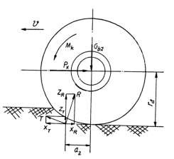
R = Z R + X R
T = Z T + X T
The point of application of the resultant force R , T will be at point
distance a 2 from the intersection of the vertical line passing through the center of the wheel axle and the road . Due to the influence of the moment M k , the value a 2 is larger than a 1 of the passive wheel.
2.4.2. Determination of rolling resistance and rolling resistance coefficient
Figure 2.5. Force diagram acting on the driving wheel
To determine the rolling resistance, we also use the moment balance equation for all forces about the wheel axle center.
M k = (Z R + Z T )a 2 + (X T - X R )r d (2-10)
In which: Z 2 = Z R + Z T
P x = X T - X R = X k (2-11)
With : Z 2 - resultant force of perpendicular reactions of the road acting on the driving wheel X k - propulsive reaction of the road
Substitute (2-11) into (2-10) and simplify to get:
M k = Z 2 a 2 + X k r đ (2-12)
On the other hand we have:
Z 2 a 2 = G b2 a 2 = P f2 r d = M f2 with P f2 = X R (2-13)
P f2 = Z 2 a 2 = G b2 a 2 (2-14)
r d
Let f 2 =
r d
a 2 (2-15)
r d
With: f 2 is the rolling resistance coefficient of the driving wheel with the road surface.
From that we have: P f2 = f 2 .Z 2 = G b2 .f 2
M f2 , P f2 - are the rolling resistance moment and rolling resistance force of the driving wheel, respectively.
Due to the influence of the moment M k , the loss due to deformation of the active wheel is greater than that of the passive wheel (a 2 >a 1 ). This proves that the rolling resistance coefficient of the active wheel is greater than that of the passive wheel. However, to simplify the calculation, the rolling resistance coefficients of the active and passive wheels are considered the same.
2.4.3. Factors affecting rolling resistance coefficient
Through analyzing the nature of rolling resistance and the formula for calculating rolling resistance and rolling resistance coefficient, we see that the factors causing deformation of tires and roads all affect rolling resistance.
affect rolling resistance and rolling resistance coefficient. Influencing factors include:
- Physical properties and state of the road surface through the degree of road deformation and deformation between the tire and the road surface
- The load acting on the wheel (symbol G b ) is a factor that directly affects the radial deformation of the tire and the compression deformation of the road. The higher the load, the higher the deformation and the greater the resistance.
- The material used to make the tire and the air pressure in the tire also affect the deformation of the tire. Therefore, when the car moves on different types of roads, people need to adjust the tire pressure to reduce rolling resistance.
- The torque acting on the driving wheel causes circular deformation of the tire fibers, increasing internal friction in the tire, thereby increasing rolling resistance.
- The higher the vehicle speed, the higher the deformation speed, the internal friction in the tire increases, thereby increasing the rolling resistance. Experiments show that when the vehicle speed is less than 80km/h (equivalent to 22.2 m/s), the rolling resistance coefficient remains almost unchanged, but when the vehicle speed is greater than 80km/h, the rolling resistance coefficient will change and increase according to the formula:
f = f v 2
(2-16)
0 1 1500
In which: f 0 - rolling resistance coefficient corresponding to vehicle speed v < 22.2 m/s.
Value of rolling resistance coefficient f 0 on some types of roads (table 2.1)
v - vehicle speed in m/s
Table 2.1. Rolling resistance coefficient of some types of roads (according to [3], page 54)
Type of sugar
Rolling resistance coefficient corresponding to speed v 22.2 m/s (80 km/h) | ||
Concrete road | 0.012 | 0.015 |
Good asphalt | 0.015 | 0.018 |
Paved road | 0.023 | 0.030 |
Dry dirt road | 0.025 | 0.035 |
Sugar | 0.010 | 0.030 |
Maybe you are interested!
-
 Tourist Routes Are Routes Connecting Tourist Areas, Tourist Attractions, Tourist Service Providers, Associated With Road and Rail Traffic Routes
 -
 Bridge and road structure - Ho Chi Minh City College of Construction Part 2 - 9
 -
 Strengthening state management by law in the field of road traffic in Vietnam today - 10
 -
 Research on the application of smartphone utility software to evaluate traffic noise and road surface iri index - 14
 -
 Research on Building Bot Contract Templates for Road Traffic Projects
2.5. Slippage of the driving wheel
2.5.1. Concept of slippage
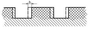
When the wheels roll, under the effect of active torque, the wheels have grips on the ground, pressing the ground horizontally and in the opposite direction to the rotational direction.
vehicle movement. The soil will be compressed a Figure 2. 6. Diagram of the main wheel slippage
dynamic
Section b makes the wheel axle move back a distance compared to the undeformed case. Because
This causes the vehicle to lose its forward speed and that is the nature of the spin slip phenomenon.
In addition, the tangential deformation of the tire fibers under the effect of torque Mk also reduces the vehicle's translational speed, causing slippage. This is explained as follows: when the tire elements enter the contact area, they will be compressed, causing the actual radius of the wheel to become smaller, thus reducing the distance the vehicle can travel after one rotation. Therefore, torque is the main cause of slippage in the driving wheel.
When the wheel is braking, under the effect of braking torque, the ground will be compressed in the same direction as the direction of the vehicle's movement. Therefore, the wheel axle moves forward a distance compared to the case of no deformation. Therefore, the actual speed of the vehicle is increased, which is the nature of the phenomenon of skidding. On the other hand, the tangential deformation of the tire fibers under the effect of braking torque also increases the speed of the vehicle, causing skidding in the braking wheels. In addition, the load, tire material, tire pressure and road surface conditions are also the causes of skidding in the wheels.
2.5.2. Slip coefficient and slip:
+ Slip coefficient and sliding when pulling:
The wheel slippage is expressed through the slip coefficient.
k :
v v o v 1 r l
(2.17)
v
v
r
k
oob
The degree of wheel slip is assessed through the slippage.
k :
k k 100%
+ Slip coefficient and braking slip:
(2.18)
In the case of braking, we have the following slip coefficient and slippage:
v v o v v o 1 r b 1
(2.19)
l
p vvvr
p p 100%
2.5.3. Method of determining slip coefficient
(2.20)
The slippage of the driving wheel is evaluated by the slip coefficient, denoted by and determined by the following formula:
v 1 etc.r 0
1
etc.
1 r
100%
(2-21)
1
Or you can write:
1 1
n 0
1
n
100%
b
(2-22)
In which: - slip in percentage
v 1 - theoretical speed of the car
v- actual speed of the driving wheel
r b - actual radius of the driving wheel r 1 - theoretical radius of the driving wheel
n 0 - number of revolutions of the driving wheel when no load n b - actual number of revolutions of the driving wheel
When the car is moving, one can determine the number of revolutions of the driving wheel when not loaded and consider that in this case the wheel slippage is very small and can be ignored. It should be noted that during the process of car movement, the following phenomena may occur:
- Rolling without slipping on passive and unbraked wheels.
- Rolling has rotational slip on the driving wheel and is having traction.
- Rolling with skidding on the braked wheel.
2.5.3.1. Non-slip rolling wheels:
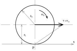
In this case, the speed of the wheel center (which is also the speed of the car) is equal to the rotational speed. That is, the actual speed v is equal to the theoretical speed v o , we have:
v v o b r b
(2.23)
Therefore, the instantaneous center of rotation (pole P) of the wheel lies on the wheel ring and
Rolling radius equals calculated radius: Figure 2. 7. Rolling without slipping.
r l = r b (2.24)
This state is only obtained in the passive wheel with M p = 0, then v 0