elastic . The tangent modulus or over-elastic modulus of the buckling load is defined by substituting E T for E in Equation 10.3 for elastic behavior.
2 E
` T(10.5)
T ( KL / r ) 2
The combined elastic and hyperelastic buckling curves (according to Euler and tangent modulus) are shown in Figure 4.6. The transition point representing the change from elastic to plastic behavior is the proportional limit prop of formula (4.4) and the corresponding slenderness ratio ( KL / r ) prop .
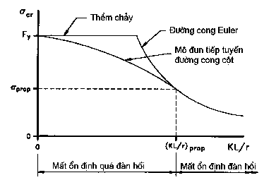
Figure 10.6 - Conjugate tangent module and column curve according to Euler
10.3. COMPRESSIVE STRENGTH
The axial compressive strength of a short column is maximum when buckling does not occur and the entire cross-section has a yield stress F y . The fully yield load P y is the maximum load that the column can withstand and can be used to normalize column curves so that they are independent of the structural steel grade. The axial yield load is:
P AF (10.6)
ysy
For long columns, the Euler ultimate buckling load P cr is obtained by multiplying Equation 10.3 by
A s :
P cr
2 EA
S
K L / r 2
(10.7)
When dividing expression 10.7 by expression 4.6, we have the formula to determine the elastic column curve
P r 2 2 E 1
Euler standard:
cr
P KL F 2
(10.8)
With c
yyc
is the slenderness limit of the column:
KL
r
c
(10.9)
F y E
The Euler column curve and the standard yield bed are shown as the top curve in Figure 10.7. The over-elastic transition curve is also shown. The column curve taking into account the further reduction in buckling load due to the initial curvature is the bottom curve in Figure 10.7.
10.7. This bottom line is the column strength curve used in the design standard.
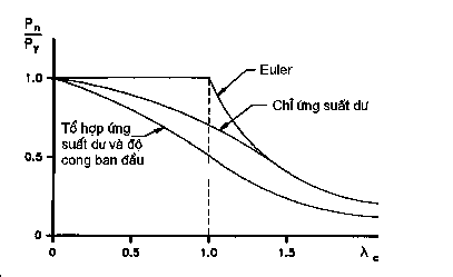
Figure 10.7 - Standard column curve with effects of imperfections.
The strength curve of a column reflects a combination of elastic and hyperelastic behavior. Hyperelastic buckling occurs for columns with average lengths from c = 0 to c = prop , where prop is the slenderness limit for an Euler critical stress prop (Equation 10.4). Elastic buckling occurs for long columns with c larger than prop . Substituting Equation 10.4 and these definitions into Equation 10.8, we obtain:
F y rc
A s 1
or 2
1
(10.10)
FA 2
prop
ys prop
1 rc
F y
The value of prop depends on the relative magnitude of the compressive residual stress rc and the yield stress F y . For example, if F y = 345 MPa and rc = 190 MPa, then Equation 10.10 gives
2
prop
12, 23 and prop = 1.49.
1 190
345
The larger the residual stress, the larger the slenderness limit at which the transition to elastic instability occurs. Almost all columns designed in practice behave as overly elastic mid-length columns. It is rare to find columns that are slender enough to behave as elastic long columns, buckling at the Euler critical load .
10.3.1.Nominal compressive strength
To avoid the radical in formula 10.9, the column slenderness limit is redefined as follows:
KL 2 F
c
r
2 y
E
(10.11)
The transition point between elastic buckling and elastic buckling or between medium-length and long-length columns is determined corresponding to = 2.25. For long columns ( ≥ 2.25), intensity
column nominal P n
(10.12)
given by:
P 0.88 F y As n
Is the Euler ultimate buckling load of formula 10.7 multiplied by a reduction factor of 0.88 to take into account the initial curvature of L /1500. For medium length columns ( < 2.25), the nominal strength of the column P n is determined from the tangent modulus curve with a smooth transition between P n = P y and the Euler buckling curve . The formula for the transition curve is:
P 0.66 FA (10.13)
nys
The curves describing formulas 10.12 and 10.13 shown in Figure 4.8 correspond to c and not to maintain the shape of the curve as shown previously in Figures 10.6 and 10.7. The final step in determining the compressive strength of the column is to multiply the nominal strength P n by the coefficient of resistance to compression c taken from Table 10.1, i.e.:
rcn
P P (10.14)
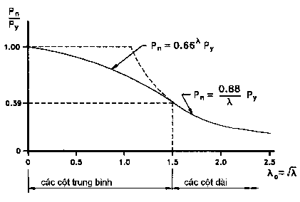
Figure 10.8 - Design column curve.
10.3.2.Limited width/thickness ratio
E
F y
The compressive strength of a medium-length column is based on the tangent modulus curve obtained from a cantilever test. A typical stress-strain curve of a cantilever column is shown in Figure 4.5. Since the cantilever column is relatively short, it will not experience bending instability. However, local instability with consequent reduction in load-bearing capacity may occur if the width/thickness ratio of the column members is too large. Therefore, the slenderness of the plates
must satisfy:
(10.15)
b kt
Where, k is the plate buckling factor taken from Table 10.1, b is the plate width given in Table 10.1 (mm) and t is the plate thickness (mm). The requirements given in Table 10.1 for plates supported longitudinally on one edge and plates supported longitudinally on two edges are illustrated in Figure 10.9.
10.3.3.Limited slenderness ratio
If the columns are too thin, they will have very little strength and be uneconomical. The limit is designed
The recommended value for main load-bearing members is ( KL / r ) 120 ( KL / r ) 140 .
EXAMPLE 10.1
and for the structural bars are
P
cn
Calculate the design compressive strength of a W360 x 110 column with a length of 6100 mm
and two pin-connected ends. Use grade 250 construction steel.
Features
Look up from AISC (1992): A s = 14100 mm 2 , d = 360 mm, t w = 11.4 mm, b f = 256 mm, t f = 19.9 mm, h c /t w = 25.3 , r x = 153 mm, r y = 62.9 mm.
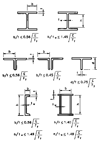
Figure 10.9 - Limiting width/thickness ratios
Table 10.1 - Limiting width/thickness ratios
The panels are supported along
one side
k | b | |
The edges and projections of the plate | 0.56 | Half-wing width of section I Overall width of the U-section Distance between free edge and first bolt line or weld line in plate Overall width of an angle bar protruding for a pair of angles placed close together |
Body of T-rolled Steel | 0.75 | Total height of T steel |
Other exposed details | 0.45 | Overall width of one overhanging angle steel flange for single angle steel strut or double angle steel strut placed not closely Overall width of overhang for other cases |
The panels are supported along two sides | k | b |
The box edges and covers | 1.4 | Clear distance between walls minus inside corner radius on each side for the edge plates of a box section Clear distance between welds |
Maybe you are interested!
-

 Basic Electronic Engineering - Ho Chi Minh City College of Construction Part 2 - 7
 -
 Basic Electronic Engineering - Ho Chi Minh City College of Construction Part 1 - 11
 -
 Basic Electronic Engineering - Ho Chi Minh City College of Construction Part 1 - 9
 -
 Electronic Engineering - Ho Chi Minh City College of Transport - 31
 -
 Marketing Management - Ho Chi Minh City College of Construction Part 2 - 6
or bolts for wing covers | ||||||
Other panel walls | and | the | structure | case | 1.49 | Clear distance between the edge plates minus the radius of curvature for the wall of the rolled steel beam Clearance between edge supports for other cases |
Cover plates with holes | 1.86 | Clearance between edge supports | ||||
References
[1] Nguyen Quoc Thai. Steel structure . University of Transport, 1980.
[2] Bridge design standards 22 TCN 272-01 . Ministry of Transport.
[3] Le Dinh Tam. Steel bridge . Transport Publishing House, 2003.
[4] Richard M. Barker; Jay A. Puckett. Design of highway bridges . Wiley Interscience Publishing House, 1997.
[5] William T. Segui. LRFD Steel Design . Thomson Brooks/Cole, 2003.
[6] Nguyen Viet Trung; Hoang Ha. Simple span reinforced concrete bridges, volume I. Transport Publishing House, 2003.