Wrong
Set t=1 week
Set x = first day
Database
Rules
Repeat comparing the data with the rule patterns taken from the database (starting from x )
(t weeks/all weeks taken)
Count duplicates with 10%-20% error.
Wrong
If t> 5 weeks
correct
Repeat with x< x +numberofdays(t)
correct
Call the algorithm to find new rules
correct
If R>= 80%
Sort samples by R,
Accept sample with R max
Wrong
Calculate the ratio R=Number of duplicates/total number of calculations, Save R in the result evaluation table
Increase t=t+ 1 week

Table 4.3 Algorithm diagram for finding rules from rule sample database.
An illustrative example of applying the above two algorithms to find treatment rules: Suppose there are the following two sample rules:
Date order
1 | 2 | 3 | 4 | 5 | 6 | 7 | |
Rule 1 (dosage/day) | 1 | 2 | 1 | 2 | 1 | 2 | 1 |
Rule 2 (dosage/day) | 1 | 1 | 1 | 2 | 1 | 1 | 1 |
Maybe you are interested!
-
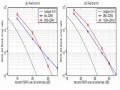
 d-blast algorithm in mimo technology - 8
 -
 d-blast algorithm in mimo technology - 7
 -
 D. Service Provider Structure Customer Survey Sample Card
 -
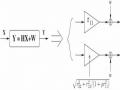
 Pascal's Triangle Rule O(N,k) Is Comb(N,k) And We Have The Following Algorithm:
 -
 Car body electrical practice - 8
zt2i3t4l5ee
zt2a3gs
zt2a3ge
zc2o3n4t5e6n7ts
If the voltage is out of specification, replace the wire or connector.
If the voltage is within specification, install the front fog light relay and follow step 5.
Step 5 Check the front fog light switch
- Remove the D4 connector of the fog light switch
- Use a multimeter to measure the resistance of the front fog light switch.
Measurement location
Condition
Standard
D4-3 (BFG) -D4-4 (LFG)
Light switchFront Fog OFF
>10kΩ
D4-3 (BFG) -D4-4 (LFG)
Front fog light switchON
<1 Ω
- Standard resistor
D4 connector is located on the combination switch assembly.
If the resistance is out of specification, replace the combination switch (the fog light switch is located in the combination switch).
If the resistance is within specification, follow step 6.
Step 6 Check wiring and connectors (front fog light relay-light selector switch)
- Disconnect connector D4 of the combination switch assembly
- Use a voltmeter to measure the voltage value of jack D4 on the wire side.
Measurement location
Control modecontrol
Standard
D4-3 (BFG) - (-) AQ
TAIL
11 to 14 V
D4 connector for the wiring of the combination switch assembly
If the voltage does not meet the standard, replace the wire or connector.
If the voltage is within standard, there may have been an error in the previous measurements.
Step 7 Check the front fog lights
- Remove the front fog light electrical connector.
- Supply battery voltage to the fog lamp terminals
Jack 8, B9 of front fog lamp on the electrical side
blind first.
Power supply location
Terms and Conditions
Battery positive terminal - Terminal 2Battery negative terminal - Terminal 1
Fog lightsbefore morning
- If the light does not come on, replace the bulb.
If the light is on, re-plug the jack and continue to step 8.
Step 8 Check wiring and connectors (relay and front fog lights)
- Disconnect the B8 and B9 connectors of the front fog lights.
- Use a voltmeter to measure voltage at the following locations:
Measurement location
Switch location
Terms and Conditions
B8-2 - (-) AQ
Electric lock ON TAIL size switchFog switch ON
11 to 14 V
B9-2 - (-) AQ
Electric lock ONTAIL size switch Fog switch ON
11 to 14 V
B8 and B9 connectors on the front fog lamp wiring side
Voltage is not up to standard, repair or replace the jack. If up to standard, there may have been an error in the measurement process.
2.2.4. Procedure for removing, installing and adjusting fog lights 1. Procedure for removing
- Remove the front inner ear pads
Use a screwdriver to remove the 3 screws and remove the front part of the front inner ear liner
-Remove the fog light assembly
+ Disconnect the connector.
+ Use a screwdriver to remove 3 screws to remove the fog light cover
2. Installation sequence
-Rotate the fog lamp bulb in the direction indicated by the arrow as shown in the figure and remove the fog lamp from the fog lamp assembly.
-Rotate the fog light bulb in the direction indicated by the arrow as shown in the figure and install the light into the fog light assembly.
- Use a screwdriver to install the fog light cover
-Install the electrical connector
Attention: Be careful not to damage the plastic thread on the lamp assembly.
- Install the front inner ear pads
Use a screwdriver to install the front inner bumper with 3 screws.
3. Prepare the vehicle to adjust the fog light convergence. Prepare the vehicle:
- Make sure there is no damage or deformation to the vehicle body around the fog lights.
- Add fuel to the fuel tank
- Add oil to standard level.
- Add engine coolant to standard level.
- Inflate the tire to standard pressure.
- Place spare tire, tools and jack in original design position
- Do not leave any load in the luggage compartment.
- Let a person weighing about 75 kg sit in the driver's seat.
4. Prepare to check the fog light convergence
a/ Prepare the vehicle status as follows:
- Place the car in a dark enough place to see the lines. The lines are the dividing line, below which the light from the fog lights can be seen but above which it cannot.
- Place the car perpendicular to the wall.
- Keep a distance of 7.62 m between the center of the fog lamp and the wall.
- Park the car on level ground.
- Press the car down a few times to stabilize the suspension.
Note: A distance of approximately 7.62 m is required between the vehicle (fog lamp center) and the wall to adjust the convergence correctly. If the distance of 7.62 m cannot be achieved, set the correct distance of 3 m to check and adjust the fog lamp convergence. (Since the target area varies with the distance, please follow the instructions as shown in the figure.)
b/ Prepare a piece of thick white paper about 2 m high and 4 m wide to use as a screen.
c/ Draw a vertical line through the center of the screen (line V).
d/ Set the screen as shown in the picture. Note:
- Keep the screen perpendicular to the ground.
- Align the V line on the screen with the center of the vehicle.
e/Draw the reference lines (H, V LH and V RH lines) on the screen as shown in the figure.HINT:
Mark the center of the fog lamp on the screen. If the center mark cannot be seen on the fog lamp, use the center of the fog lamp or the manufacturer's name mark on the fog lamp as the center mark.
H line (fog light height):
Draw a line across the screen so that it passes through the center mark. Line H should be at the same height as the center mark of the fog light bulb.
Line V LH, V RH (center mark position of left fog lamp LH and right fog lamp RH):
Draw two lines so that they intersect line H at the center marks.
5. Check the fog light convergence
a/ Cover the fog lamp or remove the connector of the other side fog lamp to prevent light from the unchecked fog lamp from affecting the fog lamp convergence test.
b/ Start the engine.
c/ Turn on the fog lights and make sure that the dividing line is outside the standard area as shown in the drawing.
6. Adjust the fog light convergence
Use a screwdriver to adjust the fog light to the standard area by turning the toe adjustment screw.
Note: If the screw is adjusted too far, loosen it and then tighten it again, so that the last rotation of the light adjustment screw is clockwise.
3. Self-study questions
1. Describe the operating principle of the lighting system with automatic headlight function
2. Describe the operating principle of the lighting system with the function of rotating headlights when turning
3. Draw diagram and connect lighting system on Hyundai Porter car
4. Draw diagram and connect lighting system on Honda Accord 1992
5. Draw the lighting circuit on a 1993 Toyota Lexus
LESSON 3 MAINTENANCE AND REPAIR OF SIGNAL SYSTEM
I. IMPLEMENTATION GOAL
After completing this lesson, students will be able to:
- Distinguish between types of signals on cars
- Correctly describe common symptoms and suspected areas causing damage.
- Connecting signal circuits ensures technical requirements
- Disassemble, install, check, maintain and repair the signal system to ensure technical requirements.
- Ensure safety in work and industrial hygiene
II. LESSON CONTENT
1. General description
The signal system equipped on cars aims to create signals to notify other vehicles participating in traffic about the vehicle's operating status such as: stopping, parking, braking, reversing, turning...
Signals are used either by light such as headlamps, brake lights, turn signals….. or by sound such as horns, reverse music….
Just like the lighting system. A signal system circuit usually consists of: battery, fuse, wire, relay, electrical load and control switch. Only some switches of the signal system are on the combination switch. The switches of other signals are usually located in different locations such as in the gearbox or brake pedal……
2. Maintenance and repair
2.1. Turn signals and hazard lights
The installation location of the turn signal is shown in Figure 3.1. The turn signal control switch is located in the combination switch under the steering wheel. Turning this switch to the right or left will make the turn signal turn right or left.
The hazard light switch is used when the vehicle has a problem while participating in traffic. When the hazard light switch is turned on, all the turn signals on the vehicle will light up at a certain frequency. The hazard light switch is usually placed separately from the turn signal switch (some old cars integrate the hazard and turn signal switches on the same combination switch cluster).
Figure 3.1 Turn signal switch Figure 3.2 Hazard switch
The part that generates the flashing frequency for the lights is called a turn signal relay. The turn signal relay usually has 3 terminals: B (positive power supply); E (negative power supply); L (providing the turn signal switch to distribute to the
lamp)
2.1.1. Circuit diagram
To generate the frequency for the turn signal, a turn signal relay is used in the turn signal circuit. The current from the turn signal relay will be sent to the turn signal switch assembly to distribute the current to the turn signal lights for the driver's purpose.
Figure 3.3. Schematic diagram of a turn signal circuit without a hazard switch
1. Battery; 2. Electric lock; 3. Turn signal relay; 4. Turn signal switch; 5. Turn signal lamp; 6. Turn signal lamp; 7. Hazard switch
Figure 3.4 Schematic diagram of turn signal circuit with hazard switch
1. Battery; 2. Combination switch cluster; 3. Turn signal;
4. Turn signal light; 5. Turn signal relay
Today's cars no longer use three-pin turn signal relays (B, L, E) but use eight-pin turn signal relays (figure 3.5) (pin number 8 is used for hazard lights).
For this type, the current supplying the turn signal lights is supplied directly from the turn signal relay to the lights.
div.maincontent .p { color: black; font-family:"Times New Roman", serif; font-style: normal; font-weight: normal; text-decoration: none; font-size: 14pt; margin:0pt; } div.maincontent p { color: black; font-family:"Times New Roman", serif; font-style: normal; font-weight: normal; text-decoration: none; font-size: 14pt; margin:0pt; } div.maincontent .s1 { color: black; font-family:"Times New Roman", serif; font-style: normal; font-weight: normal; text-decoration: none; font-size: 13pt; } div.maincontent .s2 { color: black; font-family:"Times New Roman", serif; font-style: italic; font-weight: normal; text-decoration: none; font-size: 14pt; } div.maincontent .s3 { color: black; font-family:"Times New Roman", serif; font-style: normal; font-weight: normal; text-decoration: none; font-size: 14pt; } div.maincontent .s4 { color: black; font-family:"Times New Roman", serif; font-style: normal; font-weight: normal; text-decoration: none; font-size: 13pt; } div.maincontent .s5 { color: black; font-family:"Times New Roman", serif; font-style: normal; font-weight: normal; text-decoration: none; font-size: 13pt; vertical-align: 1pt; } div.maincontent .s6 { color: black; font-family:"Times New Roman", serif; font-style: normal; font-weight: normal; text-decoration: none; font-size: 11pt; } div.maincontent .s7 { color: black; font-family:"Times New Roman", serif; font-style: normal; font-weight: normal; text-decoration: none; font-size: 14pt; vertical-align: -9pt; } div.maincontent .s8 { color: black; font-family:"Times New Roman", serif; font-style: normal; font-weight: normal; text-decoration: none; font-size: 11pt; } div.maincontent .s9 { color: #008000; font-family:"Times New Roman", serif; font-style: normal; font-weight: normal; text-decoration: none; font-size: 14pt; } div.maincontent .s10 { color: black; font-family:"Times New Roman", serif; font-style: italic; font-weight: normal; te
Car body electrical practice - 8
zt2i3t4l5ee
zt2a3gs
zt2a3ge
zc2o3n4t5e6n7ts
If the voltage is out of specification, replace the wire or connector.
If the voltage is within specification, install the front fog light relay and follow step 5.
Step 5 Check the front fog light switch
- Remove the D4 connector of the fog light switch
- Use a multimeter to measure the resistance of the front fog light switch.
Measurement location
Condition
Standard
D4-3 (BFG) -D4-4 (LFG)
Light switchFront Fog OFF
>10kΩ
D4-3 (BFG) -D4-4 (LFG)
Front fog light switchON
<1 Ω
- Standard resistor
D4 connector is located on the combination switch assembly.
If the resistance is out of specification, replace the combination switch (the fog light switch is located in the combination switch).
If the resistance is within specification, follow step 6.
Step 6 Check wiring and connectors (front fog light relay-light selector switch)
- Disconnect connector D4 of the combination switch assembly
- Use a voltmeter to measure the voltage value of jack D4 on the wire side.
Measurement location
Control modecontrol
Standard
D4-3 (BFG) - (-) AQ
TAIL
11 to 14 V
D4 connector for the wiring of the combination switch assembly
If the voltage does not meet the standard, replace the wire or connector.
If the voltage is within standard, there may have been an error in the previous measurements.
Step 7 Check the front fog lights
- Remove the front fog light electrical connector.
- Supply battery voltage to the fog lamp terminals
Jack 8, B9 of front fog lamp on the electrical side
blind first.
Power supply location
Terms and Conditions
Battery positive terminal - Terminal 2Battery negative terminal - Terminal 1
Fog lightsbefore morning
- If the light does not come on, replace the bulb.
If the light is on, re-plug the jack and continue to step 8.
Step 8 Check wiring and connectors (relay and front fog lights)
- Disconnect the B8 and B9 connectors of the front fog lights.
- Use a voltmeter to measure voltage at the following locations:
Measurement location
Switch location
Terms and Conditions
B8-2 - (-) AQ
Electric lock ON TAIL size switchFog switch ON
11 to 14 V
B9-2 - (-) AQ
Electric lock ONTAIL size switch Fog switch ON
11 to 14 V
B8 and B9 connectors on the front fog lamp wiring side
Voltage is not up to standard, repair or replace the jack. If up to standard, there may have been an error in the measurement process.
2.2.4. Procedure for removing, installing and adjusting fog lights 1. Procedure for removing
- Remove the front inner ear pads
Use a screwdriver to remove the 3 screws and remove the front part of the front inner ear liner
-Remove the fog light assembly
+ Disconnect the connector.
+ Use a screwdriver to remove 3 screws to remove the fog light cover
2. Installation sequence
-Rotate the fog lamp bulb in the direction indicated by the arrow as shown in the figure and remove the fog lamp from the fog lamp assembly.
-Rotate the fog light bulb in the direction indicated by the arrow as shown in the figure and install the light into the fog light assembly.
- Use a screwdriver to install the fog light cover
-Install the electrical connector
Attention: Be careful not to damage the plastic thread on the lamp assembly.
- Install the front inner ear pads
Use a screwdriver to install the front inner bumper with 3 screws.
3. Prepare the vehicle to adjust the fog light convergence. Prepare the vehicle:
- Make sure there is no damage or deformation to the vehicle body around the fog lights.
- Add fuel to the fuel tank
- Add oil to standard level.
- Add engine coolant to standard level.
- Inflate the tire to standard pressure.
- Place spare tire, tools and jack in original design position
- Do not leave any load in the luggage compartment.
- Let a person weighing about 75 kg sit in the driver's seat.
4. Prepare to check the fog light convergence
a/ Prepare the vehicle status as follows:
- Place the car in a dark enough place to see the lines. The lines are the dividing line, below which the light from the fog lights can be seen but above which it cannot.
- Place the car perpendicular to the wall.
- Keep a distance of 7.62 m between the center of the fog lamp and the wall.
- Park the car on level ground.
- Press the car down a few times to stabilize the suspension.
Note: A distance of approximately 7.62 m is required between the vehicle (fog lamp center) and the wall to adjust the convergence correctly. If the distance of 7.62 m cannot be achieved, set the correct distance of 3 m to check and adjust the fog lamp convergence. (Since the target area varies with the distance, please follow the instructions as shown in the figure.)
b/ Prepare a piece of thick white paper about 2 m high and 4 m wide to use as a screen.
c/ Draw a vertical line through the center of the screen (line V).
d/ Set the screen as shown in the picture. Note:
- Keep the screen perpendicular to the ground.
- Align the V line on the screen with the center of the vehicle.
e/Draw the reference lines (H, V LH and V RH lines) on the screen as shown in the figure.HINT:
Mark the center of the fog lamp on the screen. If the center mark cannot be seen on the fog lamp, use the center of the fog lamp or the manufacturer's name mark on the fog lamp as the center mark.
H line (fog light height):
Draw a line across the screen so that it passes through the center mark. Line H should be at the same height as the center mark of the fog light bulb.
Line V LH, V RH (center mark position of left fog lamp LH and right fog lamp RH):
Draw two lines so that they intersect line H at the center marks.
5. Check the fog light convergence
a/ Cover the fog lamp or remove the connector of the other side fog lamp to prevent light from the unchecked fog lamp from affecting the fog lamp convergence test.
b/ Start the engine.
c/ Turn on the fog lights and make sure that the dividing line is outside the standard area as shown in the drawing.
6. Adjust the fog light convergence
Use a screwdriver to adjust the fog light to the standard area by turning the toe adjustment screw.
Note: If the screw is adjusted too far, loosen it and then tighten it again, so that the last rotation of the light adjustment screw is clockwise.
3. Self-study questions
1. Describe the operating principle of the lighting system with automatic headlight function
2. Describe the operating principle of the lighting system with the function of rotating headlights when turning
3. Draw diagram and connect lighting system on Hyundai Porter car
4. Draw diagram and connect lighting system on Honda Accord 1992
5. Draw the lighting circuit on a 1993 Toyota Lexus
LESSON 3 MAINTENANCE AND REPAIR OF SIGNAL SYSTEM
I. IMPLEMENTATION GOAL
After completing this lesson, students will be able to:
- Distinguish between types of signals on cars
- Correctly describe common symptoms and suspected areas causing damage.
- Connecting signal circuits ensures technical requirements
- Disassemble, install, check, maintain and repair the signal system to ensure technical requirements.
- Ensure safety in work and industrial hygiene
II. LESSON CONTENT
1. General description
The signal system equipped on cars aims to create signals to notify other vehicles participating in traffic about the vehicle's operating status such as: stopping, parking, braking, reversing, turning...
Signals are used either by light such as headlamps, brake lights, turn signals….. or by sound such as horns, reverse music….
Just like the lighting system. A signal system circuit usually consists of: battery, fuse, wire, relay, electrical load and control switch. Only some switches of the signal system are on the combination switch. The switches of other signals are usually located in different locations such as in the gearbox or brake pedal……
2. Maintenance and repair
2.1. Turn signals and hazard lights
The installation location of the turn signal is shown in Figure 3.1. The turn signal control switch is located in the combination switch under the steering wheel. Turning this switch to the right or left will make the turn signal turn right or left.
The hazard light switch is used when the vehicle has a problem while participating in traffic. When the hazard light switch is turned on, all the turn signals on the vehicle will light up at a certain frequency. The hazard light switch is usually placed separately from the turn signal switch (some old cars integrate the hazard and turn signal switches on the same combination switch cluster).
Figure 3.1 Turn signal switch Figure 3.2 Hazard switch
The part that generates the flashing frequency for the lights is called a turn signal relay. The turn signal relay usually has 3 terminals: B (positive power supply); E (negative power supply); L (providing the turn signal switch to distribute to the
lamp)
2.1.1. Circuit diagram
To generate the frequency for the turn signal, a turn signal relay is used in the turn signal circuit. The current from the turn signal relay will be sent to the turn signal switch assembly to distribute the current to the turn signal lights for the driver's purpose.
Figure 3.3. Schematic diagram of a turn signal circuit without a hazard switch
1. Battery; 2. Electric lock; 3. Turn signal relay; 4. Turn signal switch; 5. Turn signal lamp; 6. Turn signal lamp; 7. Hazard switch
Figure 3.4 Schematic diagram of turn signal circuit with hazard switch
1. Battery; 2. Combination switch cluster; 3. Turn signal;
4. Turn signal light; 5. Turn signal relay
Today's cars no longer use three-pin turn signal relays (B, L, E) but use eight-pin turn signal relays (figure 3.5) (pin number 8 is used for hazard lights).
For this type, the current supplying the turn signal lights is supplied directly from the turn signal relay to the lights.
div.maincontent .p { color: black; font-family:"Times New Roman", serif; font-style: normal; font-weight: normal; text-decoration: none; font-size: 14pt; margin:0pt; } div.maincontent p { color: black; font-family:"Times New Roman", serif; font-style: normal; font-weight: normal; text-decoration: none; font-size: 14pt; margin:0pt; } div.maincontent .s1 { color: black; font-family:"Times New Roman", serif; font-style: normal; font-weight: normal; text-decoration: none; font-size: 13pt; } div.maincontent .s2 { color: black; font-family:"Times New Roman", serif; font-style: italic; font-weight: normal; text-decoration: none; font-size: 14pt; } div.maincontent .s3 { color: black; font-family:"Times New Roman", serif; font-style: normal; font-weight: normal; text-decoration: none; font-size: 14pt; } div.maincontent .s4 { color: black; font-family:"Times New Roman", serif; font-style: normal; font-weight: normal; text-decoration: none; font-size: 13pt; } div.maincontent .s5 { color: black; font-family:"Times New Roman", serif; font-style: normal; font-weight: normal; text-decoration: none; font-size: 13pt; vertical-align: 1pt; } div.maincontent .s6 { color: black; font-family:"Times New Roman", serif; font-style: normal; font-weight: normal; text-decoration: none; font-size: 11pt; } div.maincontent .s7 { color: black; font-family:"Times New Roman", serif; font-style: normal; font-weight: normal; text-decoration: none; font-size: 14pt; vertical-align: -9pt; } div.maincontent .s8 { color: black; font-family:"Times New Roman", serif; font-style: normal; font-weight: normal; text-decoration: none; font-size: 11pt; } div.maincontent .s9 { color: #008000; font-family:"Times New Roman", serif; font-style: normal; font-weight: normal; text-decoration: none; font-size: 14pt; } div.maincontent .s10 { color: black; font-family:"Times New Roman", serif; font-style: italic; font-weight: normal; te

The dosage data for a patient under consideration are as follows:
Day
1 | 2 | 3 | 4 | 5 | 6 | 7 | 8 | 9 | 10 | 11 | 12 | 13 | 14 | 15 | 16 | 17 | ||
Dose quantity | 1 | 2 | 1 | 1 | 2 | 2 | 1 | 1 | 2 | 1 | 1 | 2 | 2 | 1 | 1 | 2 | 1 | |
Day | 18 | 19 | 20 | 21 | 22 | 23 | 24 | 25 | 26 | 27 | 28 | 29 | 30 | 31 | 32 | 33 | 34 | 35 |
Dose quantity | 1 | 2 | 2 | 1 | 1 | 2 | 1 | 1 | 2 | 2 | 1 | 1 | 2 | 1 | 1 | 2 | 2 | 1 |
Apply the rule search algorithm according to diagram 4.3, Recurrence value R (rule 1/data set under consideration)=0/5=0; Recurrence value R (rule 2/data set under consideration)=0/5=0;
The algorithm for finding rules on sample rule data does not converge. At this time, apply the algorithm for finding rules according to diagram 4.2: Get the time series value t=5 days:
Rule 1'
1 | 2 | 1 | 1 | 2 |
Recurrence value R (1' rule/considered data set)=1/7=0.143; Take the time series value t=6 days:
Rule 2'
1 | 2 | 1 | 1 | 2 | 2 |
Recurrence value R (2' rule/considered data set)=1/6=0.167; Take the time series value t=7 days:
Rule 3'
1 | 2 | 1 | 1 | 2 | 2 | 1 |
Recurrence value R (3' rule/considered data set)=5/5=1;
So the chosen rule will be Rule 3' because it has the largest repetition rate in the data set.
4.4. Combination of the above methods
In fact, a patient's treatment lasts throughout their life. Therefore, the use of a combination of dosage prediction methods will be appropriate for each stage of the treatment process. The combination method simulates the long-term treatment process for a patient. The methods of exploration, finding similar cases and finding dosage rules will be applied in turn at each different time of the treatment process, which helps to quickly determine the stable dosage of a patient. And that is also the goal of the problem.
Step 1: in the early stage of the patient: Use the method of finding the most similar sample medical records, build a backbone dosage system.
Step 2: Determine if there is a similar case history. When the method of finding similar cases is effective and used, it must still be combined with the exploration method to rely on the basic system of rules to estimate and adjust the dosage more realistically between the patient's follow-up visits.
Step 3: In case no similar medical record exists, apply the exploratory method.
Step 4: After certain periods of time (1 week, 2 weeks, 1 month, 3 months): apply the method of finding the patient's drug use pattern.
The key to this hybrid approach is the combination of prediction algorithms over treatment time. The goal is to find the most stable treatment solution for the patient. This hybrid approach can improve the system's ability to predict dosage.
New patient case
correct
Wrong
Exist?
Wrong
correct
correct
Wrong
Exist? Exist?
Use method 2: find the best sample medical record
Build the spine dosage based on method 2
Using method 1: calculate dosage according to basic rules
Use method 1: adjust dosage according to basic rules
After each re-examination
Use method 3: Find the treatment rule
Use method 3: Find the treatment rule
Dosage prediction
stable


Table 4.4 Hybrid method algorithm diagram.
Example:
Consider a patient with the following data:
Patient id
age | sex | H. | W. | Operated Date | Risk of Frozen Blood | Risk of Me. | Clinical En. | Type of Waltz | No of Waltz | Region | Epidemic | |
05-00- | Valve | Region | Hot | |||||||||
10001 | 22 | Male | 170 | 62 | 2005/4/19 | High | High | yes | 2 | Bac | Slim |
This patient's safe INR range is as follows:
Patient_id
Date | INR_Min | INR_max | Basic dose | |
05-00-10001 | 2005/9/26 | 2.5 | 3.5 | 2 |
Sample medical record as follows:
Patient id
sex | age | H. | W. | Operated Date | Risk of Frozen Blood | Risk of Me. | Clinical En. | Type of waltz | No of waltz | Region | Epidemic | |
BN1 | Male | 45 | 160 | 43 | 10/9/2005 | High | High | Atrial fibrillation, | Ball mechanics | 2 | North | Urban |
BN2 | Male | 45 | 160 | 43 | 10/9/2005 | Short | Short | history of obstruction circuit, | Disc Mechanics 1 wing | 2 | North | Urban |
BN3 | Female | 45 | 160 | 43 | 10/9/2005 | High | High | thrombosis ear, | Disc Mechanics 2 wing | 2 | North | Urban |
BN4 | Female | 45 | 160 | 43 | 10/9/2005 | Short | Short | left ventricular dysfunction heavy | More mechanics valve | 2 | North | Urban |
BN5 | Male | 45 | 160 | 43 | 10/9/2005 | High | High | Born heterologous | 2 | North | Urban |
Step 1: Calculate similar medical records.
Step 2: No medical records are satisfied because the patient entered had a surgery date 5 months earlier than the sample medical record. All similarity measures are not satisfied greater than 0.9.
Step 3: Apply the survey method: The results are returned in the following table:
No | Date | INR | Dose | INR_Pred | Dose_Pred | Err_INR | Err_Dose | |
05-00-10001 | 31 | 2005/10/26 | 6.38 | 1 | 5.88 | 0 | -0.5 | -1 |
05-00-10001 | 32 | 2005/10/27 | 6.38 | 1 | 3.5 | 1 | -2.88 | 0 |
05-00-10001 | 33 | 2005/10/28 | 6.38 | 1 | 3.5 | 1 | -2.88 | 0 |
05-00-10001 | 34 | 2005/10/29 | 6.38 | 1 | 3.5 | 1 | -2.88 | 0 |
05-00-10001 | 35 | 2005/10/30 | 6.38 | 1 | 3.5 | 1 | -2.88 | 0 |
05-00-10001 | 36 | 2005/10/31 | 6.38 | 1 | 3.5 | 1 | -2.88 | 0 |
05-00-10001 | 37 | 2005/11/1 | 1.3 | 3 | 3.5 | 1 | 2.2 | -2 |
05-00-10001 | 38 | 2005/11/2 | 1.3 | 2 | 2.5 | 3 | 1.2 | 1 |
05-00-10001 | 39 | 2005/11/3 | 1.3 | 2 | 2.5 | 3 | 1.2 | 1 |
05-00-10001 | 40 | 2005/11/4 | 1.3 | 2 | 2.5 | 3 | 1.2 | 1 |
05-00-10001 | 41 | 2005/11/5 | 1.3 | 2 | 2.5 | 3 | 1.2 | 1 |
05-00-10001 | 42 | 2005/11/6 | 1.3 | 2 | 2.5 | 3 | 1.2 | 1 |
05-00-10001 | 43 | 2005/11/7 | 1.3 | 2 | 2.5 | 3 | 1.2 | 1 |
05-00-10001 | 44 | 2005/11/8 | 1.3 | 2 | 2.5 | 3 | 1.2 | 1 |
05-00-10001 | 45 | 2005/11/9 | 1.3 | 2 | 2.5 | 3 | 1.2 | 1 |
05-00-10001 | 46 | 2005/11/10 | 1.3 | 2 | 2.5 | 3 | 1.2 | 1 |
05-00-10001 | 47 | 2005/11/11 | 2.86 | 2 | 2.86 | 2 | 0 | 0 |
05-00-10001 | 48 | 2005/11/12 | 2.86 | 3 | 2.86 | 2 | 0 | -1 |
05-00-10001 | 49 | 2005/11/13 | 2.86 | 2 | 2.86 | 2 | 0 | 0 |
05-00-10001 | 50 | 2005/11/14 | 2.86 | 3 | 2.86 | 2 | 0 | -1 |
05-00-10001 | 51 | 2005/11/15 | 2.86 | 2 | 2.86 | 2 | 0 | 0 |
05-00-10001 | 52 | 2005/11/16 | 2.86 | 3 | 2.86 | 2 | 0 | -1 |
05-00-10001 | 53 | 2005/11/17 | 2.86 | 2 | 2.86 | 2 | 0 | 0 |
05-00-10001 | 54 | 2005/11/18 | 2.86 | 3 | 2.86 | 2 | 0 | -1 |
05-00-10001 | 55 | 2005/11/19 | 2.86 | 2 | 2.86 | 2 | 0 | 0 |
05-00-10001 | 56 | 2005/11/20 | 2.86 | 3 | 2.86 | 2 | 0 | -1 |
05-00-10001 | 57 | 2005/11/21 | 2.86 | 2 | 2.86 | 2 | 0 | 0 |
05-00-10001 | 58 | 2005/11/22 | 2.86 | 3 | 2.86 | 2 | 0 | -1 |
05-00-10001 | 59 | 2005/11/23 | 2.86 | 2 | 2.86 | 2 | 0 | 0 |
05-00-10001 | 60 | 2005/11/24 | 2.86 | 3 | 2.86 | 2 | 0 | -1 |
05-00-10001 | 61 | 2005/11/25 | 2.86 | 2 | 2.86 | 2 | 0 | 0 |
05-00-10001 | 62 | 2005/11/26 | 2.86 | 3 | 2.86 | 2 | 0 | -1 |
05-00-10001 | 63 | 2005/11/27 | 2.86 | 2 | 2.86 | 2 | 0 | 0 |
05-00-10001 | 64 | 2005/11/28 | 2.86 | 3 | 2.86 | 2 | 0 | -1 |
05-00-10001 | 65 | 2005/11/29 | 2.86 | 2 | 2.86 | 2 | 0 | 0 |
05-00-10001 | 66 | 2005/11/30 | 2.86 | 3 | 2.86 | 2 | 0 | -1 |
05-00-10001 | 67 | 2005/12/1 | 2.86 | 2 | 2.86 | 2 | 0 | 0 |
05-00-10001 | 68 | 2005/12/2 | 2.86 | 3 | 2.86 | 2 | 0 | -1 |
05-00-10001 | 69 | 2005/12/3 | 2.86 | 2 | 2.86 | 2 | 0 | 0 |
05-00-10001 | 70 | 2005/12/4 | 2.86 | 3 | 2.86 | 2 | 0 | -1 |
05-00-10001 | 71 | 2005/12/5 | 2.86 | 2 | 2.86 | 2 | 0 | 0 |
05-00-10001 | 72 | 2005/12/6 | 2.86 | 3 | 2.86 | 2 | 0 | -1 |
Patient_id
Step 4: Find the treatment rule. In the above data segment, the patient came for a routine check-up on the last day (No. 72) and the INR test result was still within the safe range (2.86). Applying the rule search method on the patient's data set, using the algorithm to automatically search for the rule, the result returned is as follows:
1 | 1 1 | 1 | 1 | 1 | 3 | 2 | ||
Rule 2 | 2 | 2 | 2 | 2 | 2 | 2 | 2 | 2 |
Rule 3 | 2 | 3 | 2 | 3 | 2 | 3 | 2 | 3 |
Rule 1
Repeatability calculation results: R(rule 1)=1/5=0.2, R(rule 2)=1/5=0.2, R(rule 3)=3/5=0.6,
In this case the third rule may exist, and the third rule can be applied to the dosage calculation of subsequent stages, taking into account the patient's next follow-up visit.
In case rule 3 is applied, the dosage calculation for the following days will be based on this rule, that is, on the second day of the week, take 2/8 sintrom pills, on the third day, take 3/8 pills, on the fourth day, take 2/8 pills, on the fifth day, take 3/8 pills, on the sixth day, take 2/8 pills, on the seventh day, take 3/8 pills, on the Sunday:
Patient_id
No | Date | INR | Dose | INR_Pred | Dose_Pred | Err_INR | Err_Dose | |
05-00-10001 | 73 | 2005/12/3 | 2.86 | 2 | ||||
05-00-10001 | 74 | 2005/12/4 | 2.86 | 3 | ||||
05-00-10001 | 75 | 2005/12/5 | 2.86 | 2 | ||||
05-00-10001 | 76 | 2005/12/7 | 2.86 | 3 | ||||
05-00-10001 | 77 | 2005/12/8 | 2.86 | 2 | ||||
05-00-10001 | 78 | 2005/12/9 | 2.86 | 3 | ||||
05-00-10001 | 79 | 2005/12/10 | 2.86 | 2 |
The combination of the above three methods will clearly manifest in the whole process of predicting the patient's treatment dosage:
From day 31 to day 72 of treatment: dosage is predicted by the exploratory method.
From day 73 until the last follow-up visit, dosage was predicted using a treatment rule search method.
However, for this example, the time to apply the dosage rule calculation is too short, so it will only be used to illustrate the method of combining the three algorithms above.
Chapter 5: Building software to test algorithms for predicting anticoagulant dosage
5.1. System design
Module name | |
Patient information management section | |
STT | Related Sections |
1 | Enter general patient data |
2 | Enter patient's personal status |
3 | Enter the patient's diet |
4 | Enter the patient's lifestyle |
5 | Enter the patient's safe INR range |
6 | Enter patient's medication regimen |
Support for predicting the next dose of medication to take | |
STT | Related Sections |
1 | Apply the method of exploration, use basic fuzzy rules |
2 | Apply case-based reasoning |
3 | Apply the rule finding method patient treatment |
4 | Apply hybrid method: integrate the above 3 solutions |
STT | Related Sections |
1 | Table of vitamin K content in food |
2 | Reference medical records table |
3 | Table of types of artificial heart valves |
4 | Table of regions |
5 | Table of regions |