Use correct dosage and concentration
Use medicine properly (according to the Plant Protection Ordinance)
- Must master the method of using tools and sprayers:
Tools, sprayers and equipment used for mixing, measuring and measuring pesticides must always be ready for use. After each spraying, technical errors must be immediately corrected, any detected damage must be repaired and the sprayer must be cleaned and maintained.
Regularly check the quality of spraying by ensuring the correct working pressure of the solution (for carrier pumps) and the correct number of fan revolutions (for motor pumps). Through visual inspection of the size of the drug particles and the speed of the drug particles flying out of the nozzle.
Maybe you are interested!
-

 Car body electrical practice - 8
zt2i3t4l5ee
zt2a3gs
zt2a3ge
zc2o3n4t5e6n7ts
If the voltage is out of specification, replace the wire or connector.
If the voltage is within specification, install the front fog light relay and follow step 5.
Step 5 Check the front fog light switch
- Remove the D4 connector of the fog light switch
- Use a multimeter to measure the resistance of the front fog light switch.
Measurement location
Condition
Standard
D4-3 (BFG) -D4-4 (LFG)
Light switchFront Fog OFF
>10kΩ
D4-3 (BFG) -D4-4 (LFG)
Front fog light switchON
<1 Ω
- Standard resistor
D4 connector is located on the combination switch assembly.
If the resistance is out of specification, replace the combination switch (the fog light switch is located in the combination switch).
If the resistance is within specification, follow step 6.
Step 6 Check wiring and connectors (front fog light relay-light selector switch)
- Disconnect connector D4 of the combination switch assembly
- Use a voltmeter to measure the voltage value of jack D4 on the wire side.
Measurement location
Control modecontrol
Standard
D4-3 (BFG) - (-) AQ
TAIL
11 to 14 V
D4 connector for the wiring of the combination switch assembly
If the voltage does not meet the standard, replace the wire or connector.
If the voltage is within standard, there may have been an error in the previous measurements.
Step 7 Check the front fog lights
- Remove the front fog light electrical connector.
- Supply battery voltage to the fog lamp terminals
Jack 8, B9 of front fog lamp on the electrical side
blind first.
Power supply location
Terms and Conditions
Battery positive terminal - Terminal 2Battery negative terminal - Terminal 1
Fog lightsbefore morning
- If the light does not come on, replace the bulb.
If the light is on, re-plug the jack and continue to step 8.
Step 8 Check wiring and connectors (relay and front fog lights)
- Disconnect the B8 and B9 connectors of the front fog lights.
- Use a voltmeter to measure voltage at the following locations:
Measurement location
Switch location
Terms and Conditions
B8-2 - (-) AQ
Electric lock ON TAIL size switchFog switch ON
11 to 14 V
B9-2 - (-) AQ
Electric lock ONTAIL size switch Fog switch ON
11 to 14 V
B8 and B9 connectors on the front fog lamp wiring side
Voltage is not up to standard, repair or replace the jack. If up to standard, there may have been an error in the measurement process.
2.2.4. Procedure for removing, installing and adjusting fog lights 1. Procedure for removing
- Remove the front inner ear pads
Use a screwdriver to remove the 3 screws and remove the front part of the front inner ear liner
-Remove the fog light assembly
+ Disconnect the connector.
+ Use a screwdriver to remove 3 screws to remove the fog light cover
2. Installation sequence
-Rotate the fog lamp bulb in the direction indicated by the arrow as shown in the figure and remove the fog lamp from the fog lamp assembly.
-Rotate the fog light bulb in the direction indicated by the arrow as shown in the figure and install the light into the fog light assembly.
- Use a screwdriver to install the fog light cover
-Install the electrical connector
Attention: Be careful not to damage the plastic thread on the lamp assembly.
- Install the front inner ear pads
Use a screwdriver to install the front inner bumper with 3 screws.
3. Prepare the vehicle to adjust the fog light convergence. Prepare the vehicle:
- Make sure there is no damage or deformation to the vehicle body around the fog lights.
- Add fuel to the fuel tank
- Add oil to standard level.
- Add engine coolant to standard level.
- Inflate the tire to standard pressure.
- Place spare tire, tools and jack in original design position
- Do not leave any load in the luggage compartment.
- Let a person weighing about 75 kg sit in the driver's seat.
4. Prepare to check the fog light convergence
a/ Prepare the vehicle status as follows:
- Place the car in a dark enough place to see the lines. The lines are the dividing line, below which the light from the fog lights can be seen but above which it cannot.
- Place the car perpendicular to the wall.
- Keep a distance of 7.62 m between the center of the fog lamp and the wall.
- Park the car on level ground.
- Press the car down a few times to stabilize the suspension.
Note: A distance of approximately 7.62 m is required between the vehicle (fog lamp center) and the wall to adjust the convergence correctly. If the distance of 7.62 m cannot be achieved, set the correct distance of 3 m to check and adjust the fog lamp convergence. (Since the target area varies with the distance, please follow the instructions as shown in the figure.)
b/ Prepare a piece of thick white paper about 2 m high and 4 m wide to use as a screen.
c/ Draw a vertical line through the center of the screen (line V).
d/ Set the screen as shown in the picture. Note:
- Keep the screen perpendicular to the ground.
- Align the V line on the screen with the center of the vehicle.
e/Draw the reference lines (H, V LH and V RH lines) on the screen as shown in the figure.HINT:
Mark the center of the fog lamp on the screen. If the center mark cannot be seen on the fog lamp, use the center of the fog lamp or the manufacturer's name mark on the fog lamp as the center mark.
H line (fog light height):
Draw a line across the screen so that it passes through the center mark. Line H should be at the same height as the center mark of the fog light bulb.
Line V LH, V RH (center mark position of left fog lamp LH and right fog lamp RH):
Draw two lines so that they intersect line H at the center marks.
5. Check the fog light convergence
a/ Cover the fog lamp or remove the connector of the other side fog lamp to prevent light from the unchecked fog lamp from affecting the fog lamp convergence test.
b/ Start the engine.
c/ Turn on the fog lights and make sure that the dividing line is outside the standard area as shown in the drawing.
6. Adjust the fog light convergence
Use a screwdriver to adjust the fog light to the standard area by turning the toe adjustment screw.
Note: If the screw is adjusted too far, loosen it and then tighten it again, so that the last rotation of the light adjustment screw is clockwise.
3. Self-study questions
1. Describe the operating principle of the lighting system with automatic headlight function
2. Describe the operating principle of the lighting system with the function of rotating headlights when turning
3. Draw diagram and connect lighting system on Hyundai Porter car
4. Draw diagram and connect lighting system on Honda Accord 1992
5. Draw the lighting circuit on a 1993 Toyota Lexus
LESSON 3 MAINTENANCE AND REPAIR OF SIGNAL SYSTEM
I. IMPLEMENTATION GOAL
After completing this lesson, students will be able to:
- Distinguish between types of signals on cars
- Correctly describe common symptoms and suspected areas causing damage.
- Connecting signal circuits ensures technical requirements
- Disassemble, install, check, maintain and repair the signal system to ensure technical requirements.
- Ensure safety in work and industrial hygiene
II. LESSON CONTENT
1. General description
The signal system equipped on cars aims to create signals to notify other vehicles participating in traffic about the vehicle's operating status such as: stopping, parking, braking, reversing, turning...
Signals are used either by light such as headlamps, brake lights, turn signals….. or by sound such as horns, reverse music….
Just like the lighting system. A signal system circuit usually consists of: battery, fuse, wire, relay, electrical load and control switch. Only some switches of the signal system are on the combination switch. The switches of other signals are usually located in different locations such as in the gearbox or brake pedal……
2. Maintenance and repair
2.1. Turn signals and hazard lights
The installation location of the turn signal is shown in Figure 3.1. The turn signal control switch is located in the combination switch under the steering wheel. Turning this switch to the right or left will make the turn signal turn right or left.
The hazard light switch is used when the vehicle has a problem while participating in traffic. When the hazard light switch is turned on, all the turn signals on the vehicle will light up at a certain frequency. The hazard light switch is usually placed separately from the turn signal switch (some old cars integrate the hazard and turn signal switches on the same combination switch cluster).
Figure 3.1 Turn signal switch Figure 3.2 Hazard switch
The part that generates the flashing frequency for the lights is called a turn signal relay. The turn signal relay usually has 3 terminals: B (positive power supply); E (negative power supply); L (providing the turn signal switch to distribute to the
lamp)
2.1.1. Circuit diagram
To generate the frequency for the turn signal, a turn signal relay is used in the turn signal circuit. The current from the turn signal relay will be sent to the turn signal switch assembly to distribute the current to the turn signal lights for the driver's purpose.
Figure 3.3. Schematic diagram of a turn signal circuit without a hazard switch
1. Battery; 2. Electric lock; 3. Turn signal relay; 4. Turn signal switch; 5. Turn signal lamp; 6. Turn signal lamp; 7. Hazard switch
Figure 3.4 Schematic diagram of turn signal circuit with hazard switch
1. Battery; 2. Combination switch cluster; 3. Turn signal;
4. Turn signal light; 5. Turn signal relay
Today's cars no longer use three-pin turn signal relays (B, L, E) but use eight-pin turn signal relays (figure 3.5) (pin number 8 is used for hazard lights).
For this type, the current supplying the turn signal lights is supplied directly from the turn signal relay to the lights.
div.maincontent .p { color: black; font-family:"Times New Roman", serif; font-style: normal; font-weight: normal; text-decoration: none; font-size: 14pt; margin:0pt; } div.maincontent p { color: black; font-family:"Times New Roman", serif; font-style: normal; font-weight: normal; text-decoration: none; font-size: 14pt; margin:0pt; } div.maincontent .s1 { color: black; font-family:"Times New Roman", serif; font-style: normal; font-weight: normal; text-decoration: none; font-size: 13pt; } div.maincontent .s2 { color: black; font-family:"Times New Roman", serif; font-style: italic; font-weight: normal; text-decoration: none; font-size: 14pt; } div.maincontent .s3 { color: black; font-family:"Times New Roman", serif; font-style: normal; font-weight: normal; text-decoration: none; font-size: 14pt; } div.maincontent .s4 { color: black; font-family:"Times New Roman", serif; font-style: normal; font-weight: normal; text-decoration: none; font-size: 13pt; } div.maincontent .s5 { color: black; font-family:"Times New Roman", serif; font-style: normal; font-weight: normal; text-decoration: none; font-size: 13pt; vertical-align: 1pt; } div.maincontent .s6 { color: black; font-family:"Times New Roman", serif; font-style: normal; font-weight: normal; text-decoration: none; font-size: 11pt; } div.maincontent .s7 { color: black; font-family:"Times New Roman", serif; font-style: normal; font-weight: normal; text-decoration: none; font-size: 14pt; vertical-align: -9pt; } div.maincontent .s8 { color: black; font-family:"Times New Roman", serif; font-style: normal; font-weight: normal; text-decoration: none; font-size: 11pt; } div.maincontent .s9 { color: #008000; font-family:"Times New Roman", serif; font-style: normal; font-weight: normal; text-decoration: none; font-size: 14pt; } div.maincontent .s10 { color: black; font-family:"Times New Roman", serif; font-style: italic; font-weight: normal; te
Car body electrical practice - 8
zt2i3t4l5ee
zt2a3gs
zt2a3ge
zc2o3n4t5e6n7ts
If the voltage is out of specification, replace the wire or connector.
If the voltage is within specification, install the front fog light relay and follow step 5.
Step 5 Check the front fog light switch
- Remove the D4 connector of the fog light switch
- Use a multimeter to measure the resistance of the front fog light switch.
Measurement location
Condition
Standard
D4-3 (BFG) -D4-4 (LFG)
Light switchFront Fog OFF
>10kΩ
D4-3 (BFG) -D4-4 (LFG)
Front fog light switchON
<1 Ω
- Standard resistor
D4 connector is located on the combination switch assembly.
If the resistance is out of specification, replace the combination switch (the fog light switch is located in the combination switch).
If the resistance is within specification, follow step 6.
Step 6 Check wiring and connectors (front fog light relay-light selector switch)
- Disconnect connector D4 of the combination switch assembly
- Use a voltmeter to measure the voltage value of jack D4 on the wire side.
Measurement location
Control modecontrol
Standard
D4-3 (BFG) - (-) AQ
TAIL
11 to 14 V
D4 connector for the wiring of the combination switch assembly
If the voltage does not meet the standard, replace the wire or connector.
If the voltage is within standard, there may have been an error in the previous measurements.
Step 7 Check the front fog lights
- Remove the front fog light electrical connector.
- Supply battery voltage to the fog lamp terminals
Jack 8, B9 of front fog lamp on the electrical side
blind first.
Power supply location
Terms and Conditions
Battery positive terminal - Terminal 2Battery negative terminal - Terminal 1
Fog lightsbefore morning
- If the light does not come on, replace the bulb.
If the light is on, re-plug the jack and continue to step 8.
Step 8 Check wiring and connectors (relay and front fog lights)
- Disconnect the B8 and B9 connectors of the front fog lights.
- Use a voltmeter to measure voltage at the following locations:
Measurement location
Switch location
Terms and Conditions
B8-2 - (-) AQ
Electric lock ON TAIL size switchFog switch ON
11 to 14 V
B9-2 - (-) AQ
Electric lock ONTAIL size switch Fog switch ON
11 to 14 V
B8 and B9 connectors on the front fog lamp wiring side
Voltage is not up to standard, repair or replace the jack. If up to standard, there may have been an error in the measurement process.
2.2.4. Procedure for removing, installing and adjusting fog lights 1. Procedure for removing
- Remove the front inner ear pads
Use a screwdriver to remove the 3 screws and remove the front part of the front inner ear liner
-Remove the fog light assembly
+ Disconnect the connector.
+ Use a screwdriver to remove 3 screws to remove the fog light cover
2. Installation sequence
-Rotate the fog lamp bulb in the direction indicated by the arrow as shown in the figure and remove the fog lamp from the fog lamp assembly.
-Rotate the fog light bulb in the direction indicated by the arrow as shown in the figure and install the light into the fog light assembly.
- Use a screwdriver to install the fog light cover
-Install the electrical connector
Attention: Be careful not to damage the plastic thread on the lamp assembly.
- Install the front inner ear pads
Use a screwdriver to install the front inner bumper with 3 screws.
3. Prepare the vehicle to adjust the fog light convergence. Prepare the vehicle:
- Make sure there is no damage or deformation to the vehicle body around the fog lights.
- Add fuel to the fuel tank
- Add oil to standard level.
- Add engine coolant to standard level.
- Inflate the tire to standard pressure.
- Place spare tire, tools and jack in original design position
- Do not leave any load in the luggage compartment.
- Let a person weighing about 75 kg sit in the driver's seat.
4. Prepare to check the fog light convergence
a/ Prepare the vehicle status as follows:
- Place the car in a dark enough place to see the lines. The lines are the dividing line, below which the light from the fog lights can be seen but above which it cannot.
- Place the car perpendicular to the wall.
- Keep a distance of 7.62 m between the center of the fog lamp and the wall.
- Park the car on level ground.
- Press the car down a few times to stabilize the suspension.
Note: A distance of approximately 7.62 m is required between the vehicle (fog lamp center) and the wall to adjust the convergence correctly. If the distance of 7.62 m cannot be achieved, set the correct distance of 3 m to check and adjust the fog lamp convergence. (Since the target area varies with the distance, please follow the instructions as shown in the figure.)
b/ Prepare a piece of thick white paper about 2 m high and 4 m wide to use as a screen.
c/ Draw a vertical line through the center of the screen (line V).
d/ Set the screen as shown in the picture. Note:
- Keep the screen perpendicular to the ground.
- Align the V line on the screen with the center of the vehicle.
e/Draw the reference lines (H, V LH and V RH lines) on the screen as shown in the figure.HINT:
Mark the center of the fog lamp on the screen. If the center mark cannot be seen on the fog lamp, use the center of the fog lamp or the manufacturer's name mark on the fog lamp as the center mark.
H line (fog light height):
Draw a line across the screen so that it passes through the center mark. Line H should be at the same height as the center mark of the fog light bulb.
Line V LH, V RH (center mark position of left fog lamp LH and right fog lamp RH):
Draw two lines so that they intersect line H at the center marks.
5. Check the fog light convergence
a/ Cover the fog lamp or remove the connector of the other side fog lamp to prevent light from the unchecked fog lamp from affecting the fog lamp convergence test.
b/ Start the engine.
c/ Turn on the fog lights and make sure that the dividing line is outside the standard area as shown in the drawing.
6. Adjust the fog light convergence
Use a screwdriver to adjust the fog light to the standard area by turning the toe adjustment screw.
Note: If the screw is adjusted too far, loosen it and then tighten it again, so that the last rotation of the light adjustment screw is clockwise.
3. Self-study questions
1. Describe the operating principle of the lighting system with automatic headlight function
2. Describe the operating principle of the lighting system with the function of rotating headlights when turning
3. Draw diagram and connect lighting system on Hyundai Porter car
4. Draw diagram and connect lighting system on Honda Accord 1992
5. Draw the lighting circuit on a 1993 Toyota Lexus
LESSON 3 MAINTENANCE AND REPAIR OF SIGNAL SYSTEM
I. IMPLEMENTATION GOAL
After completing this lesson, students will be able to:
- Distinguish between types of signals on cars
- Correctly describe common symptoms and suspected areas causing damage.
- Connecting signal circuits ensures technical requirements
- Disassemble, install, check, maintain and repair the signal system to ensure technical requirements.
- Ensure safety in work and industrial hygiene
II. LESSON CONTENT
1. General description
The signal system equipped on cars aims to create signals to notify other vehicles participating in traffic about the vehicle's operating status such as: stopping, parking, braking, reversing, turning...
Signals are used either by light such as headlamps, brake lights, turn signals….. or by sound such as horns, reverse music….
Just like the lighting system. A signal system circuit usually consists of: battery, fuse, wire, relay, electrical load and control switch. Only some switches of the signal system are on the combination switch. The switches of other signals are usually located in different locations such as in the gearbox or brake pedal……
2. Maintenance and repair
2.1. Turn signals and hazard lights
The installation location of the turn signal is shown in Figure 3.1. The turn signal control switch is located in the combination switch under the steering wheel. Turning this switch to the right or left will make the turn signal turn right or left.
The hazard light switch is used when the vehicle has a problem while participating in traffic. When the hazard light switch is turned on, all the turn signals on the vehicle will light up at a certain frequency. The hazard light switch is usually placed separately from the turn signal switch (some old cars integrate the hazard and turn signal switches on the same combination switch cluster).
Figure 3.1 Turn signal switch Figure 3.2 Hazard switch
The part that generates the flashing frequency for the lights is called a turn signal relay. The turn signal relay usually has 3 terminals: B (positive power supply); E (negative power supply); L (providing the turn signal switch to distribute to the
lamp)
2.1.1. Circuit diagram
To generate the frequency for the turn signal, a turn signal relay is used in the turn signal circuit. The current from the turn signal relay will be sent to the turn signal switch assembly to distribute the current to the turn signal lights for the driver's purpose.
Figure 3.3. Schematic diagram of a turn signal circuit without a hazard switch
1. Battery; 2. Electric lock; 3. Turn signal relay; 4. Turn signal switch; 5. Turn signal lamp; 6. Turn signal lamp; 7. Hazard switch
Figure 3.4 Schematic diagram of turn signal circuit with hazard switch
1. Battery; 2. Combination switch cluster; 3. Turn signal;
4. Turn signal light; 5. Turn signal relay
Today's cars no longer use three-pin turn signal relays (B, L, E) but use eight-pin turn signal relays (figure 3.5) (pin number 8 is used for hazard lights).
For this type, the current supplying the turn signal lights is supplied directly from the turn signal relay to the lights.
div.maincontent .p { color: black; font-family:"Times New Roman", serif; font-style: normal; font-weight: normal; text-decoration: none; font-size: 14pt; margin:0pt; } div.maincontent p { color: black; font-family:"Times New Roman", serif; font-style: normal; font-weight: normal; text-decoration: none; font-size: 14pt; margin:0pt; } div.maincontent .s1 { color: black; font-family:"Times New Roman", serif; font-style: normal; font-weight: normal; text-decoration: none; font-size: 13pt; } div.maincontent .s2 { color: black; font-family:"Times New Roman", serif; font-style: italic; font-weight: normal; text-decoration: none; font-size: 14pt; } div.maincontent .s3 { color: black; font-family:"Times New Roman", serif; font-style: normal; font-weight: normal; text-decoration: none; font-size: 14pt; } div.maincontent .s4 { color: black; font-family:"Times New Roman", serif; font-style: normal; font-weight: normal; text-decoration: none; font-size: 13pt; } div.maincontent .s5 { color: black; font-family:"Times New Roman", serif; font-style: normal; font-weight: normal; text-decoration: none; font-size: 13pt; vertical-align: 1pt; } div.maincontent .s6 { color: black; font-family:"Times New Roman", serif; font-style: normal; font-weight: normal; text-decoration: none; font-size: 11pt; } div.maincontent .s7 { color: black; font-family:"Times New Roman", serif; font-style: normal; font-weight: normal; text-decoration: none; font-size: 14pt; vertical-align: -9pt; } div.maincontent .s8 { color: black; font-family:"Times New Roman", serif; font-style: normal; font-weight: normal; text-decoration: none; font-size: 11pt; } div.maincontent .s9 { color: #008000; font-family:"Times New Roman", serif; font-style: normal; font-weight: normal; text-decoration: none; font-size: 14pt; } div.maincontent .s10 { color: black; font-family:"Times New Roman", serif; font-style: italic; font-weight: normal; te -
 Measure 4: Make Tools and Toys to Use in Children's Play Activities
 -
 Perspectives on Improving the Quality of Law Application in Resolving Land Use Rights Disputes at the People's Court
 -
 Internal control of revenue and expenditure activities at the National Children's Hospital - 2
 -
 “Cronbach's Alpha Cost Factor Scale”
Correctly implement the method of spraying pesticides on the field: the spraying process is carried out against the wind, but the participants must stand upwind to avoid the sprayed pesticides being blown onto them by the wind; pesticide containers must not be thrown away carelessly but must be collected in the right place; do not clean the sprayer and tools at the source of water...
5.4. WATER PUMP
In agricultural production, water pumps are commonly used for irrigation and drainage. Current pump manufacturing technology has created many types of pumps with different working principles. However, the most popular are piston pumps and centrifugal pumps.
5.4.1. Piston pump
a. Single acting piston pump
The working principle diagram of a one-way piston pump is shown in Figure 5.15:
4
q
q
max
q
tb
3 2
π
2π φ
1
Figure 5.15: Working principle diagram of a single-acting piston pump
1 - piston; 2 - cylinder; 3 - suction valve; 4 - discharge valve
A - low pressure chamber; B - intermediate chamber; C - high pressure chamber
When the crank mechanism operates, the piston moves from left to right, the volume of the intermediate chamber B increases, causing the pressure inside to decrease, creating suction. Under the effect of that suction, valve 3 opens, water is sucked into the cylinder. When the piston moves from right to left, valve 3 closes, at the same time, under the pressure of water, valve 4 opens to let water pass through to the discharge pipe. Then the piston moves again.
from right to left, the process happens again similarly. In this way, water is brought from bottom to top, creating the work of the pump.
b. Double-acting piston pump
The working principle diagram of a one-way piston pump is shown in Figure 5.16:
4
4 *
q
tb
3
2 1
0
π
2π φ
3 *
q
q
max
Figure 5.16: Working principle diagram of a single-acting piston pump
1 - piston; 2 - cylinder; 3 - suction valve; 4 - discharge valve
A - low pressure chamber; B - intermediate chamber; C - high pressure chamber
When the piston moves from left to right, valve 3 and valve 4 * open, valve 4 and valve 3 * close, water from chamber A through inlet port 3 into left cylinder chamber B 1 , at the same time water from right cylinder chamber B 2 through valve 4 * to outlet port.
When the piston moves from right to left, valve 4 and valve 3 * open, valve 3 and valve 4 * close water from chamber A through inlet port 3 * into the right cylinder chamber B 2 , at the same time water from the left cylinder chamber B 1 through valve 4 to the outlet.
Thus, when the piston moves from right to left and when the piston moves from left to right, water is pushed to the outlet, so it is called a double-acting pump. A double-acting pump gives us a larger and more stable flow than a single-acting pump.
5.4.2. Centrifugal pumps
a. Tangential centrifugal pump
The working principle diagram of tangential centrifugal pump is shown in Figure 5.17:
The working part is the impeller 2, which consists of blades sandwiched between two rigidly mounted discs on the rotating shaft and placed in the spiral chamber of the body 3. The body 3 has an inlet connected to the suction pipe 4 and an outlet connected to the discharge pipe 8. The lower end of the suction pipe has a one-way valve 5 and a trash screen 6. Above the pump body is a water priming nozzle 1. The gap between the impeller and the pump body is tightly sealed, preventing water and air from passing through.
Before working, the impeller must be submerged in water, otherwise it must be primed through tap 1 or through discharge pipe 8. When working, the impeller rotates, pulling the water along. Under the effect of centrifugal force, water is thrown out of port 7 at high speed. Port 7 is funnel-shaped, here, the kinetic energy of the water particles will create a thrust force to push the water up through pipe 8. At the same time as the thrust process, a vacuum is generated in the center of the impeller, causing water to be sucked through the trash screen through the one-way valve and into the pump body through the suction pipe. The suction and thrust processes occur simultaneously and continuously, creating a flow from bottom to top.
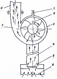
Figure 5.17: Working principle diagram of tangential centrifugal pump 1 - water priming nozzle;
2 - impeller; 3 - pump body;
4 - straw;
5 - one-way valve; 6 - mesh;
7 - outlet; 8 - discharge pipe
Tangential centrifugal pumps are capable of lifting water to great heights but with small flow rates.
b. Axial centrifugal pump
The working principle diagram of axial centrifugal pump is shown in Figure 5.18:
The working part is impeller 2, mounted on shaft 5 and located in the cylinder. The impeller has a number of spiral blades. When working, the impeller is placed in water, the motor pulls the impeller to rotate, the spiral blades push the water up.
6
5
4
3
2
1
axial direction. The 3rd streamline blades reduce the vortex of the water, making the flow straighter, thereby reducing pressure loss and increasing pump flow. At the same time as pushing the water up, the working chamber of the impeller generates a vacuum, water will be sucked from the outside into the chamber through the trash screen 1. The suction and discharge processes take place simultaneously and continuously, creating a flow from bottom to top.
The clearance between the outer rim of the impeller and the inner cylindrical surface of the working chamber must be small to ensure the required flow and discharge height. Since the impeller is always submerged in the water source, the centrifugal pump
Shaft is not primed when operating.
Axial centrifugal pumps are capable of large flow rates but the water lift height is not large.
Figure 5.18: Working principle diagram of axial centrifugal pump 1 - mesh; 2 - impeller;
3 - straightening blade; 4 - discharge pipe (pump body); 5 - shaft; 6 - pulley
5.5. PLANT GENERATOR
5.5.1. Tasks and classification
* Mission:
The generator is responsible for cutting the epidermis to create a favorable environment for plant growth or to reclaim land.
* Classification:
- According to the source of power to move the machine, we have:
+ Handheld vegetation generator
+ Tractor mounted vegetation generator
+ Self-propelled vegetation generator
- According to the movement of the working part, we have:
+ The vegetation generator has a rotating working part.
+ The vegetation generator has a rotating working part.
5.5.2. Structure and working principle of handheld vegetation generator
a. Structure
The handheld peeling machine has the structure as shown in Figure 5.19, including the main parts:
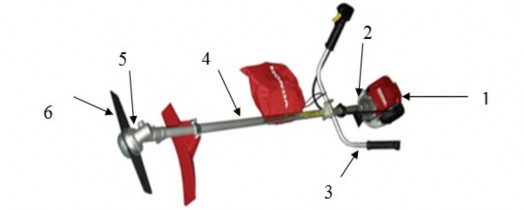
Figure 5.19: Handheld vegetation generator
1 - Engine; 2 - Clutch; 3 - Control handle; 4 - Transmission shaft; 5 - Gear box; 6 - Cutting blade
- Engine: 2-stroke gasoline engine
- Cone: is a centrifugal cone
- Transmission shaft: is a long iron shaft, placed in a long and hard tube.
- Gearbox: is a bevel gear type gear box. The two shafts of the gear box are arranged at an angle so that when the machine is worn on the body, the blade is parallel to the ground.
- Blade: is the working part of the machine, including many types:
+ Plate type blade
+ 4-bladed transmitter
+ Sawtooth blade
+ Wire-type transmitter blade
b. Working principles
When working, the engine is running, the rotation of the engine crankshaft is transmitted through the cone, transmission shaft, and then to the gearbox. The generator blade is mounted on the output shaft (passive shaft) of the gearbox, so it will rotate and perform cutting of the skin.
5.5.3. Some notes when using the wearer-type skin generator
- Prepare the work site well: before starting, you must check to detect and remove or mark unexpected obstacles such as rocks, mounds of earth, tree roots, etc.
- Before starting the machine, you must carefully check the technical condition of the machine, especially tighten the blade holding screw (note, this is a left-hand threaded screw).
- When the generator is running, absolutely do not let anyone walk in front of and alongside the generator blade.
- During work, the user must pay attention to observe and detect unexpected obstacles to avoid, at the same time, do not let the machine damage the plants, do not let the blade cut close to the ground and do not cut vegetation with stems that are too hard.
Review questions:
1. Indicate the forms of fertilization and technical requirements for fertilizer application machines.
2. Presentation, structure and operation of organic fertilizer mixer.
3. Presentation, structure and operation of organic fertilizer spreading machine.
4. Presentation, structure and operation of vertical axis inorganic fertilizer dispenser.
4. Presentation, structure and operation of disc type inorganic fertilizer dispenser.
6. Presentation, structure and operation of tiller.
7. Present the structural diagram of a sprayer based on the pressure principle. The operating structure of the piston-type and diaphragm-type pressure generators.
8. Describe the structure and operation of a sprayer based on the blowing principle.
9. Give notes on using pesticide sprayers.
10. Describe the structure and operation of a piston water pump.
11. Describe the structure and operation of a tangential centrifugal water pump.
12. Describe the structure and operation of an axial centrifugal water pump.
CHAPTER VI: AGRICULTURAL HARVESTING MACHINES
6.1. RICE HARVESTING MACHINE
6.1.1. Requirements for harvesters
- The cutting part must ensure that no plants are missed and no grain is wasted (such as cutting into the rice flower, scattering the rice flower or causing the grain to fall), total loss must not exceed 2%.
- Ability to change cutting height easily.
- The reaper can adjust position and rotation speed easily.
- In the combine harvester, the size of the rice bundle must follow a certain specification.
Rice thrown into the field must be gathered into piles.
- In the combine, rice must be arranged in continuous strips, the rice grains do not come into contact with the soil.
- The working parts are sturdy and safe. The machine is equipped with convenient features for users.
6.1.2. Classification of harvesters
Harvesters are classified in two ways:
* According to the task of completing the work and the harvesting method includes:
- Harvester and rake
- Self-raking harvester
- Harvester
- Strip harvester
* According to the method of linking with the tractor includes:
- Hanging harvester
- Hook type harvester
6.1.3. General structure and working principle
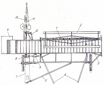
The general structure diagram of a rice harvester is as follows:
Figure 6.1: General structural diagram of the harvester
1 - cutting part; 2 - reaping wheel; 3 - rice conveyor belt; 4 - balance bar; 5 - tie bar;
6 - speed box; 7 - support; 8 - speed box of the support; 9 - drop board; 10 - support jack; 11 - transmission shaft;
12 - lifting bar
In terms of structure, the harvester consists of main parts: the harvester, the cutting part, the rice transport part, and other auxiliary parts. These parts are assembled together on the machine frame and move on the machine's wheels. When connected to the tractor, the harvester is arranged slightly off-center from the tractor so that the tractor does not run over the rice during the harvest. Because the harvester is installed slightly off-center from the tractor, the harvester loses balance during the movement process. To overcome this, a balancing part is arranged.
Operating principle: The tractor pulls the harvester into the rice field, the part that turns the rice to the harvester is neat, not spilled. The wheel rotates, the blade will sweep the rice to the cutting part, the cutting part performs the cutting of the rice. The wheel continues to rotate, the blade sweeps the rice onto the rice conveyor belt. At the same time, the next blade of the wheel will sweep the rice upright into the cutting part. That process takes place continuously until the rice hopper is full, the tractor stops, dumps the rice and then continues in the same sequence as above.
6.1.4. Main parts of the harvester
a. Threshing wheel
The task of the wheel is to push the rice into the cutting part, hold the rice for the cutting blade and toss the cut rice to the rice transfer part.
To perform the above tasks, the harvester has the following structures:
- Conventional harvester (figure 6.2):
The blades are fixed on the blades of the reaper and do not change their tilt. This type of reaper is often installed on machines for harvesting rice with upright plants or plants with insignificant tilt.
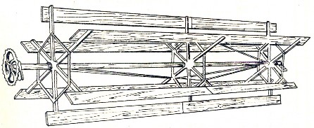
Figure 6.2: Conventional reaping wheel
- Off-center harvester (Figure 6.3):
The eccentric harvester differs from the conventional harvester in that the tilt of the blades relative to the vertical can be changed, and at all positions the blades are always parallel to each other depending on the state of the rice plant. Such a structure will be convenient when harvesting fallen rice. To achieve the above feature, the eccentric harvester has an additional sub-frame placed eccentrically from the harvester shaft at a distance equal to the length of the crank connecting the main frame to the sub-frame. This structure forms a parallelogram mechanism (two pairs of parallel sides are the rays of the frame).
main - subframe beam and swing arm connecting main frame to subframe - eccentricity between two frames.
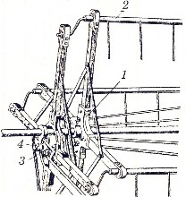
For the sub-frame, the crank is freely mounted but rigidly connected to the shaft of the wiper blade. With such a structure, when the parallelogram mechanism is displaced, all the wiper blades will rotate at a certain angle. That position will not change during the process if we keep the position of the roller frame supporting the sub-frame fixed.
- The harvester has a special structure.
Depending on the job requirements, it is necessary to create a special type of reaping wheel with a blade tilt angle that complies with the
according to a predetermined rule. The external structure is similar to a normal harvester, but on one side of the harvester is equipped with a fixed roller track. The roller on the crank of the blade mounting bar moves on that roller track. Thus, at different positions, the blade has different inclinations.
Figure 6.3: Off-center harvester 1 - main frame; 2 - blade mounting bar (reel beam); 3 - sub-frame; 4 - sub-frame support roller
b. Cutting part
There are many different types of cutting parts, but the following are commonly used today:
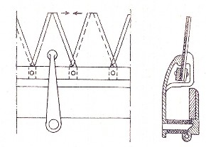
Two-knife reciprocating cutter : This type of cutter has two types: one moving knife - one fixed knife and two knives moving in opposite directions. On the knife of this type of cutter, there are isosceles triangle-shaped cutting teeth, the teeth are sharpened on both sides (Figure 6.4).
The cutting principle of this type of cutter is very simple: When the rice
The harvester blades push the rice into the gap between the two blades, which will cut the rice according to the trimmer principle.
Figure 6.4: Two-knife cutting unit
round trip translational motion
The cutting part has a knife moving in one direction (chain-knife type): The cutting blades are mounted on a roller chain. When working, the upper knife arm and the lower knife arm move in opposite directions to cut the rice (similar to the two-knife type cutting part).