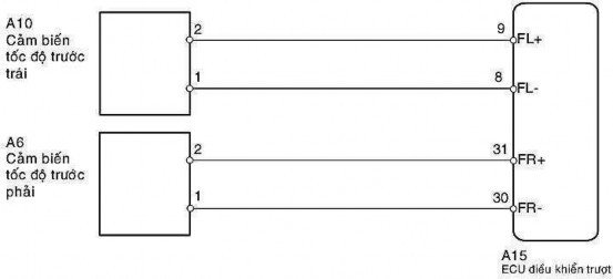
Hint: (Check the trouble codes in the repair manual of each vehicle) DTC codes C0200/31 and C1235/35 are related to the right front speed sensor. DTC codes C0205/32 and C1236/36 are related to the left front speed sensor.
113
REVIEW QUESTIONS
Question 1. Describe the preparation work when maintaining the ABS braking system? Question 2. Perform the procedure for checking for contact damage?
Question 3. Perform the procedure to check DTC codes and instantaneous data? Question 4. Perform the procedure to check the diagnostic system?
Question 5. Perform actuator inspection procedure?
Question 6. Perform the procedure for checking speed sensors?
114
115
MD 31.04. CHECK ABS BRAKE SYSTEM
* Introduce
During the operation of the ABS braking system, damage is inevitable to ensure the system operates reliably and safely. This lesson will equip students with knowledge related to maintenance and repair of the ABS braking system.
* Target:
- Explain the failure phenomena of the ABS braking system
- Read and look up specialized documents
- Able to use tools and equipment to test and diagnose ABS brake system
- Comply with procedures and regulations in automotive technology
- Train students' discipline, carefulness and meticulousness.
* Content:
1. FAULTY POINTS OF ABS BRAKE SYSTEM
1.1. Characteristics of the damaged person
Before repairing ABS, first determine whether the failure is in ABS or in the braking system. Basically, because the ABS system is equipped with a backup function, if a failure occurs in ABS, the ABS ECU immediately stops the ABS operation and switches to the normal braking system.
Since the ABS has a diagnostic function, the ABS warning light comes on to alert the driver when a malfunction has occurred. A service jack should be used to determine the source of the malfunction.
If a fault occurs in the brake system, the ABS warning light will not illuminate, so the following checks should be performed:
- Insufficient braking force.
- Only one brake is working or the brakes are locked.
- Brake pedal vibrates (when ABS is not working).
- Other checks.
Perform the above checks first. Only after making sure that there is no fault in these systems should the ABS be checked.
Note :
Special phenomena in ABS.
Although not a malfunction, the following special phenomena may occur in vehicles with ABS.
During the initial inspection, a working noise may be heard from the actuator. This is normal.
Vibration and working noise from the vehicle body and brake pedal are generated when ABS is operating, however it indicates that ABS is operating normally.
116
1.2. Cause of failure
a. Uncontrolled braking force
- Check for brake fluid leaks from the pipes or air leaks.
- Check if the brake pedal clearance is too large.
- Check the brake pad thickness to see if there is oil or grease on the brake pads.
- Check the brake booster for damage.
- Check the master brake cylinder for damage.
b. Only one brake is active or the brake is locked
- Check brake pads for uneven wear or uneven contact.
- Check the master brake cylinder for damage.
- Check if the wheel cylinder is damaged.
- Check for poor adjustment or return of the handbrake.
- Check if the brake pressure regulator valve is damaged.
c. Brake vibration when ABS is not working
- Check brake disc dirt.
- Check wheel hub wear.
d. Other checks
- Check wheel alignment.
- Check for damage in the suspension system.
- Check for uneven tire wear.
- Check the steering racks for looseness.
Table 3.1. Damage and remedies.
Problem
Possible causes | M Diagnosis *1 (m sensor check function) variable) | ||
Parts | Type of damage | ||
The “ABS” light comes on for no reason | Indicator lights and circuits | Short circuit | - |
Electric valve relay | Open circuit or | 11, 12 | |
Pump motor relay | Open circuit or | 13, 14 | |
Solenoid valve | cool | 21, 22, 23, 24 | |
Speed and rotor sensors | Broken | 31, 32, 33, 34, 35, | |
Battery and circuit source | Battery is broken, open or short | 41 | |
Speed sensor | Broken | 43 *2 , 44 *2 | |
Maybe you are interested!
-
 Testing the Necessity and Feasibility of Measures to Improve Teaching Capacity in the Field of Science and Technology for High School Teachers
 -
 Diesel engine maintenance and repair - Automotive Technology Profession For College Level Part 1 - 1
 -
 Tasks, Requirements and Methods for Diagnosing the Technical Condition of the Movement System.
 -
 Directing Innovation in Training Methods for Engineering Technology Industry According to Competency Approach
 -
 Motor electrical maintenance and repair - Automotive Technology - College Part 2 - Da Nang Vocational College - 11
117
Actuator pump | Broken | 51 | |
ECU | Broken | - | |
“ABS” indicator light does not light up within 3 seconds after turning on the key electricity | Indicator lights and circuits | Open or short circuit | - |
Pump relay and ECU | Broken | - | |
Brake operation - Brake deviation - Ineffective braking - ABS operates during normal braking (not emergency braking) - ABS operates just before stopping during normal braking. - Brake pedal vibrates abnormally | Speed and rotor sensors | Incorrect installation | (71, 72, 73, 74) |
Dirty | (71, 72, 73, 74) | ||
Rotor tooth breakage | (75, 76, 77, 78) | ||
Speed sensor | Broken | - | |
ABS controller | Broken | - | |
ECU | Broken | - | |
ABS is difficult to operate | Brake light switch | Open or short circuit | - |
Handbrake switch | Open or short circuit | - |
*1 Applicable vehicle models: Celica 10/1989; *2 For 4WD models only
2. METHODS OF TESTING AND DIAGNOSIS OF ABS BRAKE SYSTEM
2.1. Measure braking distance on the road
- Choose a long, flat stretch of road with a dry surface and high traction, with no obstacles. At 1/3 of the distance, place a marker indicating the starting point for placing your foot on the brake pedal.
- Accelerate the unloaded car to the specified speed (v), maintain this speed until the brake marker position. At the marker position, release the clutch and put your foot on the pedal and brake hard. When you step on the brake and keep the pedal still, the steering wheel is in a straight position. Wait for the car to stop.
- Measure the distance from the marker to the car's stopping position, we call this distance the braking distance. Compare with the index, evaluate. This method is quite convenient, does not require much equipment, but the disadvantage is accuracy.
118
not high, the measurement process depends on the road surface and braking status, it is dangerous to test on the road.
2.2. Measure deceleration and braking time on the road
The method is similar to the above, but requires an accelerometer with an accuracy of ± 0.1 m/s 2 and is determined by the maximum braking acceleration value on the measuring device. Measuring the maximum deceleration is a method with good accuracy that can be used to evaluate the quality of the braking system because the measuring device is small and compact (mounted on the car's windshield).
Measuring braking time requires a stopwatch with an accuracy of 1/10 of a second. The stopwatch starts when you put your foot on the brake pedal, and ends when the car comes to a complete stop.
2.3. Measure braking force or braking torque on the test stand
The basic form of brake performance measurement device by measuring the braking force at the wheel is the roller test stand.
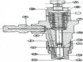
Figure 31.95. Hydraulic type automobile brake test stand.
- The brake test stand consists of three main parts: measuring stand, control cabinet and indicator.
- The measuring platform is a symmetrical device. In figure 31.95 is half of the hydraulic measuring platform, in figure 31.96 is the electric measuring platform. The display shows the force measured at the force sensor, indicating the stator induced torque. When braking to a near-lock state (wheel slippage of about 25-50%), the induced torque
119
maximum response and the device does not display subsequent values. The electrical cabinet includes circuits, automatic control relays, and a computer that stores and displays data.
- The measurement process includes the following sequences: the unloaded car, after the tire pressure has been checked, is slowly rolled onto the test stand, through the weight measuring table, and into the drum support. The engine is running but the gear lever is in neutral. The wheel must be fixed on the drum. Start the engine of the test stand, at this time due to the friction between the drum and the wheel, the wheel rolls on the drum. The driver quickly and evenly applies the brake until the wheel stops rotating and the indicator needle of the test stand gauge no longer increases. The process ends and the rear axle wheel continues onto the measuring stand.
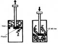
Figure 31.96. Schematic diagram of automobile brake test stand.
- The test stands can display instantaneous numbers or store and record the process of changing braking force on the wheels. Through these parameters, it shows: the overall quality of the braking system, the braking force value or braking torque of each wheel. When this braking force value is lower than the original standard, the braking mechanism may be worn, the control drive system has a problem, or the braking mechanism is locked (stuck). However, the results do not indicate damage or problems occurring in any area, which is suitable for assessing the overall quality of the braking system, through the efficiency parameter.
2.4. Measure brake force and brake pedal travel
- Measuring the braking force and brake pedal travel can be done through the driver's perception, but to get accurate values, a force meter and a length measuring ruler can be used when the vehicle is stationary on the road.
- When measuring, it is necessary to determine: Maximum braking force applied on the brake pedal, free travel of the brake pedal, distance to the floor when not braking or full brake pedal travel, remaining distance to the floor.
120