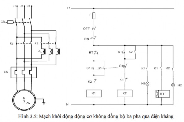
Electrical equipment description:
a. Power circuit:
- The power circuit consists of a 3-phase CB.
- Main contacts of contactor K 1and contactor K 2 .
Maybe you are interested!
-
 Design and calculation of 3-phase asynchronous motor with Squirrel Cage rotor - 1
 -
 Solutions for Investment Implementation Phase
 -
 Indirect Monitoring Through Incentives:
 -
 Starting a business Opening a coffee and ornamental plant shop - 2
 -
 Dpcsv Curve And Standard Addition Graph For Determination Of Selenium Form In Aqueous Phase After Defatting With 5ml N-Hexane (1 Time)
- Three-phase thermal relay RN.
- Three starting coils X 1 .
- Three-phase asynchronous electric motor.
- Three-phase asynchronous electric motor is supplied with three-phase four-voltage power
wire.
b. Control circuit:
- Fuse F2 is used to protect the control circuit.
- The OFF button is used to stop all circuit operations.
- Contact of thermal relay RN.
- Interlocking push button system S 1 used to start the engine.
- Contactor coils K 1 and K 2 .
- Light H 1 (green) to indicate the engine starting mode.
- H 2 light (green) to indicate long-term engine running and end of start.
- The circuit is powered by a single-phase AC power source.
Working principle:
Similar to starting through resistance, if you want the motor to operate, press S 1, contactor K 1 has power to operate, close the normally open auxiliary contact to maintain operation, light H 1 is on, when the contactor has power, it simultaneously closes the main contacts on the power circuit supplying power to the starter motor through three resistance coils. When K 1 has power, the RT time relay has power at the same time, after a predetermined time, it acts to disconnect contactor K 1 and supply power to contactor K 2 to end the process.
The braking process now powers the motor directly without going through the reactor. Lamp H 1 is off, lamp H 2 is on.
Types of protection:
- To protect the power circuit from short circuit, use a three-fuse system F 1 .
- To protect the control circuit from short circuit, use fuse F 2 .
- To protect three-phase asynchronous motors from overload, use thermal relay RN.
- To protect the 0 state for the control circuit and the power circuit combining contactor K 1 , K 2 and push button S 1 .
- To protect people and motor equipment, the control cabinet must be connected to the ground system via a PE ground wire.
Scope of application of the circuit:
Electric circuits are applied in real life in some fields such as: Starting for high-power motors, usually the main shaft drive motor in some machine tools such as lathes, vertical drilling machines, milling machines, planers such as lathes 1K62, T6M16... Drive for mixers and some lifting and transporting machines such as cranes.
3.1.2.3 Indirect 3-phase motor starting circuit via autotransformer:
Circuit diagram
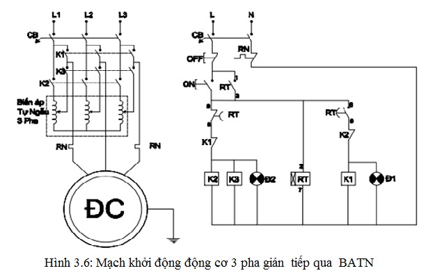
Description of electrical equipment
Power circuit:
- CB 1 : supplies power and protects the motor.
- Contact: K2 and K3 on the DL circuit close to supply power to the 3-phase autotransformer and take a voltage lower than the rated voltage to apply to the DC.
- Three contacts K1 close to connect DC directly to the grid.
- R N : thermal relay protects 2 phases of DC.
- 3 phase 6 wire DC.
Control circuit:
- CB 2 : supplies power and closes the circuit.
- Push button set: OFF, ON to stop and start the machine.
- The CTT coils K 2 and K 3 are used to control the DC when starting the motor.
- Coil K L : closes when the starting time of the DC starts. At this time, voltage U DC = U d m .
- Time relay (R t ) self-adjusts the working process of K 2 + K 3 and K 1
- The thermal relay contacts have a reset button.
Working principle
Open the machine :
- Close CB 1 and CB 2 .
- Press ON → K 2 + K 3 are powered, R t is powered.
Close the contacts of K and K on the DL circuit. The 3-phase power grid is connected to the auto transformer and a lower voltage level is taken to connect to the DC (figure). The DC is started with a low voltage (I KĐ decreases). After the set time R t, the contact 8 - 5 is opened → (K 2 + K 3 ) the power is lost, opening the contact on the DL circuit, cutting off power to the auto transformer. At the same time, 8 - 6 is closed → K 1 has power, closing the 3 main contacts on the DL circuit. Connect the DC directly to the grid; the DC voltage at this time is equal to U đ m (I đ m ).
The auxiliary contact of R t (1-3) maintains the power to the coil.
Stop machine :
- Press OFF: CTT coil loses power, opens contact on DL circuit to cut DC off from grid.
Types of protection
- When there is an incident: CB 1 , CB 2 , R N act to protect the DC.
3.1.2.4 Indirect 3-phase motor starting circuit using star-delta connection method:
Manual star-delta starting circuit 1 direction rotation
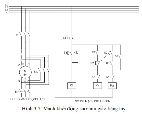
a. Power circuit:
- The power circuit consists of a 3-phase CB.
- Main contacts of contactor K 1 , contactor K 2 and contactor K 3
- 3 phase thermal relay RN.
- Three-phase asynchronous electric motor is powered from a three-phase four-wire power source.
b. Control circuit:
- Fuse F2 is used to protect the control circuit.
- The OFF button is used to stop all circuit operations.
- The interlocking push button system S 1 and S 2 is used to stop and start the engine directly.
- Contacts of Thermal Relay RN.
- Contactor coils K 1 , K 2 and K 3 , Time relay coil.
- H 1 light (dark blue) indicates the engine running mode.
- H 2 light (light blue) indicates the engine running mode.
- The control circuit is powered by a single-phase AC power source.
Operating principle of the circuit diagram: Starting the engine:
When supplying power to the 3-phase, 4-wire electrical system, the motor control system is not operating yet, the H 1 and H 2 lights are not on, indicating that the motor is in inactive (stop) mode.
To start the motor, we press the S1 button, contactor K 1 has power to close its auxiliary contact K 1 (connected in parallel with the S1 -ON button) to maintain the operation of coil K 1. When contactor K 1 has power, it closes the normally open contacts K 1 in the control circuit supplying power to the coil contactor K Y. When contactor K Y has power, it closes the K Y contact to supply power to the motor running in Y mode. Press the S 2 button , CTT K Y loses power, K ∆ has power to supply power to the motor running in delta mode.
Stop engine:
To stop the motor, press the OFF button to open the contactor coil K 1 and K ∆.leads to contactor contactor K 1and K ∆Power failure returns their contacts to their original state. The main contacts on the power circuit also return to their original state (newly opened state), disconnecting the 3-phase asynchronous electric motor from the 3-phase power grid.
Types of protection:
- To protect the power circuit from short circuit, three fuses F 1 system
- To protect the control circuit from short circuit with fuse F 2 .
- To protect 3-phase asynchronous motor from overload, use RN relay.
- To protect the 0 state for the control circuit and the power circuit combining contactor K 1, K 2 , K 3 push buttons S 1 , S 2 and time relay RT.
- To protect people and equipment, the control cabinet must be connected to the grounding system via a PE ground wire.
Scope of application of the circuit:
Electric circuits are applied in real life in some fields such as main shaft transmission in some machine tools such as lathes, vertical potato machines, milling machines, planers such as lathes... Transmission for mixers in food processing factories, cement factories...
Automatic one-way rotation star-delta circuit
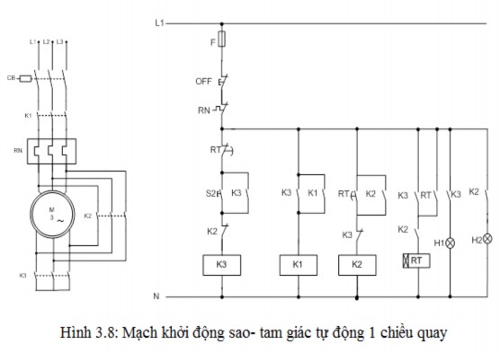
Electrical equipment description:
a. Power circuit:
- The power circuit consists of a 3-phase CB.
- Main contacts of contactor K 1 , contactor K 2and contactor K 3
- 3 phase thermal relay RN.
- Three-phase asynchronous electric motor is powered from a three-phase four-wire power source.
b. Control circuit:
- Fuse F2 is used to protect the control circuit.
- The OFF button is used to stop all circuit operations.
- The interlocking push button system S 1 and S 2 is used to stop and start the engine directly.
- Contacts of Thermal Relay RN.
- Contactor coils K 1 , K 2 and K 3 , Time relay coil.
- H 1 light (dark blue) indicates the engine running mode.
- H 2 light (light blue) indicates the engine running mode.
- The control circuit is powered by a single-phase AC power source.
Operating principle of the circuit diagram: Starting the engine:
How to run:
When supplying power to the 3-phase, 4-wire electrical system, the motor control system is not operating yet, the H 1 and H 2 lights are not on, indicating that the motor is in inactive (stop) mode.
To start the motor, we press the contactor K 3 button to close its auxiliary contact K 3 (connected in parallel with the S 1 -ON button) to maintain the operation of the coil K 3. At the same time, the S 1 OFF button also disconnects the contactor K 2 circuit . When the contactor K 3 has power, it switches the normally open contacts K 3 in the control circuit to supply power to the contactor coil K 1. The time relay operates, the H 1 light is on to indicate that the motor is operating in star mode. When the contactor K 3 has power, it simultaneously opens the normally closed contact K 3 on the contactor K 2 circuit to ensure safety and disconnect the power to operate K 3 .
When contactor K 3 and K 1 have power, in addition to closing and opening the contacts of the control circuit, they also close the main contacts on the motor circuit to supply power to the 3-phase asynchronous electric motor to start in star mode.
Triangle run:
After a preset time, the time relay opens the normally open and slow-close contacts and simultaneously closes the normally open and slow-close contacts. When contactor K 3 loses power, light H 1 turns off. Contactor K 2 has power and closes its auxiliary contacts (connected in parallel with the normally open and slow-close contacts of the Time Relay) to maintain operation for coil K 2. At this time, contactor K 1 is energized.
When contactor K 2 is energized, it closes the normally open contact K 2, the control circuit supplies power to light H 2 to indicate that the motor is operating in delta mode, and at the same time opens the normally closed contact on the side of contactor K 3 to ensure safety by cutting off the power when K 2 is operating.
When contactor K 2has power in addition to closing and opening its contacts on the control circuit and simultaneously closing the 3 main contacts on the power circuit. The sources for 3-phase asynchronous electric motors operate long-term in delta mode.
Stop engine:
To stop the motor, press the OFF button to open the contactor coil K 1 and K 2 , causing the contactor K 1 and K 2 to lose power, returning their contacts to their original state, the light H 2 is off. The main contacts on the power circuit also return to their original state (newly opened state), cutting the 3-phase asynchronous electric motor off from the 3-phase grid.
Types of protection:
- To protect the power circuit from short circuit, three fuses F 1 system
- To protect the control circuit from short circuit with fuse F 2 .
- To protect 3-phase asynchronous motor from overload, use RN relay.
- To protect the 0 state for the control circuit and the power circuit combining contactor K 1, K 2 , K 3 push buttons S 1 , S 2 and time relay RT.
- To protect people and equipment, the control cabinet must be connected to the grounding system via a PE ground wire.
Scope of application of the circuit:
Electric circuits are applied in real life in some fields such as main shaft transmission in some machine tools such as lathes, vertical potato machines, milling machines, planers such as lathes... Transmission for mixers in food processing factories, cement factories...
Star-delta starting circuit with rotation reversal:
Circuit diagram:
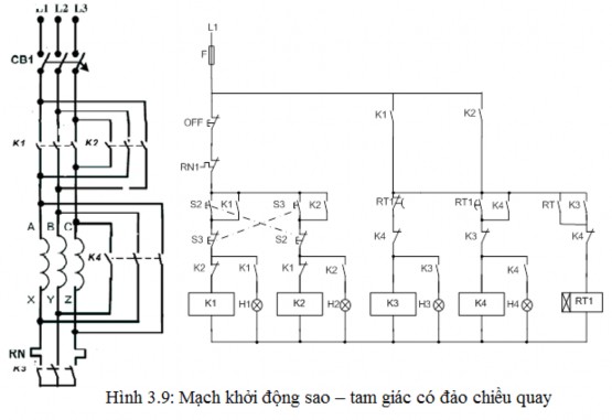
Electrical equipment description:
a. Power circuit:
- The power circuit consists of a 3-phase CB.
- Main contacts of contractor K1, K2, K3, K4
- 3 phase thermal relay RN1
- 3-phase asynchronous electric motor
- The three-phase asynchronous electric motor is powered from a three-phase four-wire power source.
b. Control circuit:
- Fuse F2 is used to protect the control circuit.
- OFF button is used to stop all activities of the circuit.
- Interlocking push button system S2, S3 is used to directly start the engine.
muscle.
- Contacts of thermal relay RN1, RN2
- Contractor coil K1, K2, K3, K4
- H1 light to indicate the right running engine mode
- H2 light to indicate left engine mode.
- H3 light indicates star-connected engine mode.
- H5 light to indicate the mode of the delta-connected engine.
- The control circuit is powered by AC power.
single phase
Working principle of the circuit diagram:
When S2 is pressed, contractor K1 is energized and self-maintained, and the RT1 time relay contractor K3 is energized. The motor must run in star mode. After a pre-adjusted time, K3 is open-circuited and K4 is energized, the motor