34
This large change in external environmental conditions in a short period of time is a major factor affecting the equipment on the outside of the satellite such as solar panels or thermal management units. Although the equipment inside the satellite (which is well insulated) is not affected much, the failure of the thermal management unit to operate properly within the specified temperature range can lead to the temperature inside the satellite exceeding the allowable level, or lack of power supply to the satellite if the solar panels do not operate within the correct temperature range [66].
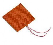
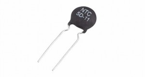
Thermal control on a satellite is usually accomplished by balancing the heat generated by the satellite as its equipment operates and interacts with the external environment (there are no gas molecules, so there is no convection). Figure 1.16 shows a film and a thermistor used to manage the heat of a small satellite. The film has copper wires inside, and when an electric current is applied, the copper wires heat up and warm the satellite components.
Maybe you are interested!
-

 Proportion of Highly Liquid Assets Before and After Deducting Loans from State Bank and Commercial Banks in the Market of Some Commercial Banks
 -
 Adhesion of Liquid Metal Particles to Solid Surfaces
 -
![Molecular Interactions at the Air/Liquid Interface [105]](https://tailieuthamkhao.com/uploads/2022/07/13/nghien-cuu-xay-dung-he-chat-hoat-dong-be-mat-ben-nhiet-ung-dung-trong-14-1-120x90.jpg) Molecular Interactions at the Air/Liquid Interface [105]
Molecular Interactions at the Air/Liquid Interface [105] -
 Car body electrical practice - 8
zt2i3t4l5ee
zt2a3gs
zt2a3ge
zc2o3n4t5e6n7ts
If the voltage is out of specification, replace the wire or connector.
If the voltage is within specification, install the front fog light relay and follow step 5.
Step 5 Check the front fog light switch
- Remove the D4 connector of the fog light switch
- Use a multimeter to measure the resistance of the front fog light switch.
Measurement location
Condition
Standard
D4-3 (BFG) -D4-4 (LFG)
Light switchFront Fog OFF
>10kΩ
D4-3 (BFG) -D4-4 (LFG)
Front fog light switchON
<1 Ω
- Standard resistor
D4 connector is located on the combination switch assembly.
If the resistance is out of specification, replace the combination switch (the fog light switch is located in the combination switch).
If the resistance is within specification, follow step 6.
Step 6 Check wiring and connectors (front fog light relay-light selector switch)
- Disconnect connector D4 of the combination switch assembly
- Use a voltmeter to measure the voltage value of jack D4 on the wire side.
Measurement location
Control modecontrol
Standard
D4-3 (BFG) - (-) AQ
TAIL
11 to 14 V
D4 connector for the wiring of the combination switch assembly
If the voltage does not meet the standard, replace the wire or connector.
If the voltage is within standard, there may have been an error in the previous measurements.
Step 7 Check the front fog lights
- Remove the front fog light electrical connector.
- Supply battery voltage to the fog lamp terminals
Jack 8, B9 of front fog lamp on the electrical side
blind first.
Power supply location
Terms and Conditions
Battery positive terminal - Terminal 2Battery negative terminal - Terminal 1
Fog lightsbefore morning
- If the light does not come on, replace the bulb.
If the light is on, re-plug the jack and continue to step 8.
Step 8 Check wiring and connectors (relay and front fog lights)
- Disconnect the B8 and B9 connectors of the front fog lights.
- Use a voltmeter to measure voltage at the following locations:
Measurement location
Switch location
Terms and Conditions
B8-2 - (-) AQ
Electric lock ON TAIL size switchFog switch ON
11 to 14 V
B9-2 - (-) AQ
Electric lock ONTAIL size switch Fog switch ON
11 to 14 V
B8 and B9 connectors on the front fog lamp wiring side
Voltage is not up to standard, repair or replace the jack. If up to standard, there may have been an error in the measurement process.
2.2.4. Procedure for removing, installing and adjusting fog lights 1. Procedure for removing
- Remove the front inner ear pads
Use a screwdriver to remove the 3 screws and remove the front part of the front inner ear liner
-Remove the fog light assembly
+ Disconnect the connector.
+ Use a screwdriver to remove 3 screws to remove the fog light cover
2. Installation sequence
-Rotate the fog lamp bulb in the direction indicated by the arrow as shown in the figure and remove the fog lamp from the fog lamp assembly.
-Rotate the fog light bulb in the direction indicated by the arrow as shown in the figure and install the light into the fog light assembly.
- Use a screwdriver to install the fog light cover
-Install the electrical connector
Attention: Be careful not to damage the plastic thread on the lamp assembly.
- Install the front inner ear pads
Use a screwdriver to install the front inner bumper with 3 screws.
3. Prepare the vehicle to adjust the fog light convergence. Prepare the vehicle:
- Make sure there is no damage or deformation to the vehicle body around the fog lights.
- Add fuel to the fuel tank
- Add oil to standard level.
- Add engine coolant to standard level.
- Inflate the tire to standard pressure.
- Place spare tire, tools and jack in original design position
- Do not leave any load in the luggage compartment.
- Let a person weighing about 75 kg sit in the driver's seat.
4. Prepare to check the fog light convergence
a/ Prepare the vehicle status as follows:
- Place the car in a dark enough place to see the lines. The lines are the dividing line, below which the light from the fog lights can be seen but above which it cannot.
- Place the car perpendicular to the wall.
- Keep a distance of 7.62 m between the center of the fog lamp and the wall.
- Park the car on level ground.
- Press the car down a few times to stabilize the suspension.
Note: A distance of approximately 7.62 m is required between the vehicle (fog lamp center) and the wall to adjust the convergence correctly. If the distance of 7.62 m cannot be achieved, set the correct distance of 3 m to check and adjust the fog lamp convergence. (Since the target area varies with the distance, please follow the instructions as shown in the figure.)
b/ Prepare a piece of thick white paper about 2 m high and 4 m wide to use as a screen.
c/ Draw a vertical line through the center of the screen (line V).
d/ Set the screen as shown in the picture. Note:
- Keep the screen perpendicular to the ground.
- Align the V line on the screen with the center of the vehicle.
e/Draw the reference lines (H, V LH and V RH lines) on the screen as shown in the figure.HINT:
Mark the center of the fog lamp on the screen. If the center mark cannot be seen on the fog lamp, use the center of the fog lamp or the manufacturer's name mark on the fog lamp as the center mark.
H line (fog light height):
Draw a line across the screen so that it passes through the center mark. Line H should be at the same height as the center mark of the fog light bulb.
Line V LH, V RH (center mark position of left fog lamp LH and right fog lamp RH):
Draw two lines so that they intersect line H at the center marks.
5. Check the fog light convergence
a/ Cover the fog lamp or remove the connector of the other side fog lamp to prevent light from the unchecked fog lamp from affecting the fog lamp convergence test.
b/ Start the engine.
c/ Turn on the fog lights and make sure that the dividing line is outside the standard area as shown in the drawing.
6. Adjust the fog light convergence
Use a screwdriver to adjust the fog light to the standard area by turning the toe adjustment screw.
Note: If the screw is adjusted too far, loosen it and then tighten it again, so that the last rotation of the light adjustment screw is clockwise.
3. Self-study questions
1. Describe the operating principle of the lighting system with automatic headlight function
2. Describe the operating principle of the lighting system with the function of rotating headlights when turning
3. Draw diagram and connect lighting system on Hyundai Porter car
4. Draw diagram and connect lighting system on Honda Accord 1992
5. Draw the lighting circuit on a 1993 Toyota Lexus
LESSON 3 MAINTENANCE AND REPAIR OF SIGNAL SYSTEM
I. IMPLEMENTATION GOAL
After completing this lesson, students will be able to:
- Distinguish between types of signals on cars
- Correctly describe common symptoms and suspected areas causing damage.
- Connecting signal circuits ensures technical requirements
- Disassemble, install, check, maintain and repair the signal system to ensure technical requirements.
- Ensure safety in work and industrial hygiene
II. LESSON CONTENT
1. General description
The signal system equipped on cars aims to create signals to notify other vehicles participating in traffic about the vehicle's operating status such as: stopping, parking, braking, reversing, turning...
Signals are used either by light such as headlamps, brake lights, turn signals….. or by sound such as horns, reverse music….
Just like the lighting system. A signal system circuit usually consists of: battery, fuse, wire, relay, electrical load and control switch. Only some switches of the signal system are on the combination switch. The switches of other signals are usually located in different locations such as in the gearbox or brake pedal……
2. Maintenance and repair
2.1. Turn signals and hazard lights
The installation location of the turn signal is shown in Figure 3.1. The turn signal control switch is located in the combination switch under the steering wheel. Turning this switch to the right or left will make the turn signal turn right or left.
The hazard light switch is used when the vehicle has a problem while participating in traffic. When the hazard light switch is turned on, all the turn signals on the vehicle will light up at a certain frequency. The hazard light switch is usually placed separately from the turn signal switch (some old cars integrate the hazard and turn signal switches on the same combination switch cluster).
Figure 3.1 Turn signal switch Figure 3.2 Hazard switch
The part that generates the flashing frequency for the lights is called a turn signal relay. The turn signal relay usually has 3 terminals: B (positive power supply); E (negative power supply); L (providing the turn signal switch to distribute to the
lamp)
2.1.1. Circuit diagram
To generate the frequency for the turn signal, a turn signal relay is used in the turn signal circuit. The current from the turn signal relay will be sent to the turn signal switch assembly to distribute the current to the turn signal lights for the driver's purpose.
Figure 3.3. Schematic diagram of a turn signal circuit without a hazard switch
1. Battery; 2. Electric lock; 3. Turn signal relay; 4. Turn signal switch; 5. Turn signal lamp; 6. Turn signal lamp; 7. Hazard switch
Figure 3.4 Schematic diagram of turn signal circuit with hazard switch
1. Battery; 2. Combination switch cluster; 3. Turn signal;
4. Turn signal light; 5. Turn signal relay
Today's cars no longer use three-pin turn signal relays (B, L, E) but use eight-pin turn signal relays (figure 3.5) (pin number 8 is used for hazard lights).
For this type, the current supplying the turn signal lights is supplied directly from the turn signal relay to the lights.
div.maincontent .p { color: black; font-family:"Times New Roman", serif; font-style: normal; font-weight: normal; text-decoration: none; font-size: 14pt; margin:0pt; } div.maincontent p { color: black; font-family:"Times New Roman", serif; font-style: normal; font-weight: normal; text-decoration: none; font-size: 14pt; margin:0pt; } div.maincontent .s1 { color: black; font-family:"Times New Roman", serif; font-style: normal; font-weight: normal; text-decoration: none; font-size: 13pt; } div.maincontent .s2 { color: black; font-family:"Times New Roman", serif; font-style: italic; font-weight: normal; text-decoration: none; font-size: 14pt; } div.maincontent .s3 { color: black; font-family:"Times New Roman", serif; font-style: normal; font-weight: normal; text-decoration: none; font-size: 14pt; } div.maincontent .s4 { color: black; font-family:"Times New Roman", serif; font-style: normal; font-weight: normal; text-decoration: none; font-size: 13pt; } div.maincontent .s5 { color: black; font-family:"Times New Roman", serif; font-style: normal; font-weight: normal; text-decoration: none; font-size: 13pt; vertical-align: 1pt; } div.maincontent .s6 { color: black; font-family:"Times New Roman", serif; font-style: normal; font-weight: normal; text-decoration: none; font-size: 11pt; } div.maincontent .s7 { color: black; font-family:"Times New Roman", serif; font-style: normal; font-weight: normal; text-decoration: none; font-size: 14pt; vertical-align: -9pt; } div.maincontent .s8 { color: black; font-family:"Times New Roman", serif; font-style: normal; font-weight: normal; text-decoration: none; font-size: 11pt; } div.maincontent .s9 { color: #008000; font-family:"Times New Roman", serif; font-style: normal; font-weight: normal; text-decoration: none; font-size: 14pt; } div.maincontent .s10 { color: black; font-family:"Times New Roman", serif; font-style: italic; font-weight: normal; te
Car body electrical practice - 8
zt2i3t4l5ee
zt2a3gs
zt2a3ge
zc2o3n4t5e6n7ts
If the voltage is out of specification, replace the wire or connector.
If the voltage is within specification, install the front fog light relay and follow step 5.
Step 5 Check the front fog light switch
- Remove the D4 connector of the fog light switch
- Use a multimeter to measure the resistance of the front fog light switch.
Measurement location
Condition
Standard
D4-3 (BFG) -D4-4 (LFG)
Light switchFront Fog OFF
>10kΩ
D4-3 (BFG) -D4-4 (LFG)
Front fog light switchON
<1 Ω
- Standard resistor
D4 connector is located on the combination switch assembly.
If the resistance is out of specification, replace the combination switch (the fog light switch is located in the combination switch).
If the resistance is within specification, follow step 6.
Step 6 Check wiring and connectors (front fog light relay-light selector switch)
- Disconnect connector D4 of the combination switch assembly
- Use a voltmeter to measure the voltage value of jack D4 on the wire side.
Measurement location
Control modecontrol
Standard
D4-3 (BFG) - (-) AQ
TAIL
11 to 14 V
D4 connector for the wiring of the combination switch assembly
If the voltage does not meet the standard, replace the wire or connector.
If the voltage is within standard, there may have been an error in the previous measurements.
Step 7 Check the front fog lights
- Remove the front fog light electrical connector.
- Supply battery voltage to the fog lamp terminals
Jack 8, B9 of front fog lamp on the electrical side
blind first.
Power supply location
Terms and Conditions
Battery positive terminal - Terminal 2Battery negative terminal - Terminal 1
Fog lightsbefore morning
- If the light does not come on, replace the bulb.
If the light is on, re-plug the jack and continue to step 8.
Step 8 Check wiring and connectors (relay and front fog lights)
- Disconnect the B8 and B9 connectors of the front fog lights.
- Use a voltmeter to measure voltage at the following locations:
Measurement location
Switch location
Terms and Conditions
B8-2 - (-) AQ
Electric lock ON TAIL size switchFog switch ON
11 to 14 V
B9-2 - (-) AQ
Electric lock ONTAIL size switch Fog switch ON
11 to 14 V
B8 and B9 connectors on the front fog lamp wiring side
Voltage is not up to standard, repair or replace the jack. If up to standard, there may have been an error in the measurement process.
2.2.4. Procedure for removing, installing and adjusting fog lights 1. Procedure for removing
- Remove the front inner ear pads
Use a screwdriver to remove the 3 screws and remove the front part of the front inner ear liner
-Remove the fog light assembly
+ Disconnect the connector.
+ Use a screwdriver to remove 3 screws to remove the fog light cover
2. Installation sequence
-Rotate the fog lamp bulb in the direction indicated by the arrow as shown in the figure and remove the fog lamp from the fog lamp assembly.
-Rotate the fog light bulb in the direction indicated by the arrow as shown in the figure and install the light into the fog light assembly.
- Use a screwdriver to install the fog light cover
-Install the electrical connector
Attention: Be careful not to damage the plastic thread on the lamp assembly.
- Install the front inner ear pads
Use a screwdriver to install the front inner bumper with 3 screws.
3. Prepare the vehicle to adjust the fog light convergence. Prepare the vehicle:
- Make sure there is no damage or deformation to the vehicle body around the fog lights.
- Add fuel to the fuel tank
- Add oil to standard level.
- Add engine coolant to standard level.
- Inflate the tire to standard pressure.
- Place spare tire, tools and jack in original design position
- Do not leave any load in the luggage compartment.
- Let a person weighing about 75 kg sit in the driver's seat.
4. Prepare to check the fog light convergence
a/ Prepare the vehicle status as follows:
- Place the car in a dark enough place to see the lines. The lines are the dividing line, below which the light from the fog lights can be seen but above which it cannot.
- Place the car perpendicular to the wall.
- Keep a distance of 7.62 m between the center of the fog lamp and the wall.
- Park the car on level ground.
- Press the car down a few times to stabilize the suspension.
Note: A distance of approximately 7.62 m is required between the vehicle (fog lamp center) and the wall to adjust the convergence correctly. If the distance of 7.62 m cannot be achieved, set the correct distance of 3 m to check and adjust the fog lamp convergence. (Since the target area varies with the distance, please follow the instructions as shown in the figure.)
b/ Prepare a piece of thick white paper about 2 m high and 4 m wide to use as a screen.
c/ Draw a vertical line through the center of the screen (line V).
d/ Set the screen as shown in the picture. Note:
- Keep the screen perpendicular to the ground.
- Align the V line on the screen with the center of the vehicle.
e/Draw the reference lines (H, V LH and V RH lines) on the screen as shown in the figure.HINT:
Mark the center of the fog lamp on the screen. If the center mark cannot be seen on the fog lamp, use the center of the fog lamp or the manufacturer's name mark on the fog lamp as the center mark.
H line (fog light height):
Draw a line across the screen so that it passes through the center mark. Line H should be at the same height as the center mark of the fog light bulb.
Line V LH, V RH (center mark position of left fog lamp LH and right fog lamp RH):
Draw two lines so that they intersect line H at the center marks.
5. Check the fog light convergence
a/ Cover the fog lamp or remove the connector of the other side fog lamp to prevent light from the unchecked fog lamp from affecting the fog lamp convergence test.
b/ Start the engine.
c/ Turn on the fog lights and make sure that the dividing line is outside the standard area as shown in the drawing.
6. Adjust the fog light convergence
Use a screwdriver to adjust the fog light to the standard area by turning the toe adjustment screw.
Note: If the screw is adjusted too far, loosen it and then tighten it again, so that the last rotation of the light adjustment screw is clockwise.
3. Self-study questions
1. Describe the operating principle of the lighting system with automatic headlight function
2. Describe the operating principle of the lighting system with the function of rotating headlights when turning
3. Draw diagram and connect lighting system on Hyundai Porter car
4. Draw diagram and connect lighting system on Honda Accord 1992
5. Draw the lighting circuit on a 1993 Toyota Lexus
LESSON 3 MAINTENANCE AND REPAIR OF SIGNAL SYSTEM
I. IMPLEMENTATION GOAL
After completing this lesson, students will be able to:
- Distinguish between types of signals on cars
- Correctly describe common symptoms and suspected areas causing damage.
- Connecting signal circuits ensures technical requirements
- Disassemble, install, check, maintain and repair the signal system to ensure technical requirements.
- Ensure safety in work and industrial hygiene
II. LESSON CONTENT
1. General description
The signal system equipped on cars aims to create signals to notify other vehicles participating in traffic about the vehicle's operating status such as: stopping, parking, braking, reversing, turning...
Signals are used either by light such as headlamps, brake lights, turn signals….. or by sound such as horns, reverse music….
Just like the lighting system. A signal system circuit usually consists of: battery, fuse, wire, relay, electrical load and control switch. Only some switches of the signal system are on the combination switch. The switches of other signals are usually located in different locations such as in the gearbox or brake pedal……
2. Maintenance and repair
2.1. Turn signals and hazard lights
The installation location of the turn signal is shown in Figure 3.1. The turn signal control switch is located in the combination switch under the steering wheel. Turning this switch to the right or left will make the turn signal turn right or left.
The hazard light switch is used when the vehicle has a problem while participating in traffic. When the hazard light switch is turned on, all the turn signals on the vehicle will light up at a certain frequency. The hazard light switch is usually placed separately from the turn signal switch (some old cars integrate the hazard and turn signal switches on the same combination switch cluster).
Figure 3.1 Turn signal switch Figure 3.2 Hazard switch
The part that generates the flashing frequency for the lights is called a turn signal relay. The turn signal relay usually has 3 terminals: B (positive power supply); E (negative power supply); L (providing the turn signal switch to distribute to the
lamp)
2.1.1. Circuit diagram
To generate the frequency for the turn signal, a turn signal relay is used in the turn signal circuit. The current from the turn signal relay will be sent to the turn signal switch assembly to distribute the current to the turn signal lights for the driver's purpose.
Figure 3.3. Schematic diagram of a turn signal circuit without a hazard switch
1. Battery; 2. Electric lock; 3. Turn signal relay; 4. Turn signal switch; 5. Turn signal lamp; 6. Turn signal lamp; 7. Hazard switch
Figure 3.4 Schematic diagram of turn signal circuit with hazard switch
1. Battery; 2. Combination switch cluster; 3. Turn signal;
4. Turn signal light; 5. Turn signal relay
Today's cars no longer use three-pin turn signal relays (B, L, E) but use eight-pin turn signal relays (figure 3.5) (pin number 8 is used for hazard lights).
For this type, the current supplying the turn signal lights is supplied directly from the turn signal relay to the lights.
div.maincontent .p { color: black; font-family:"Times New Roman", serif; font-style: normal; font-weight: normal; text-decoration: none; font-size: 14pt; margin:0pt; } div.maincontent p { color: black; font-family:"Times New Roman", serif; font-style: normal; font-weight: normal; text-decoration: none; font-size: 14pt; margin:0pt; } div.maincontent .s1 { color: black; font-family:"Times New Roman", serif; font-style: normal; font-weight: normal; text-decoration: none; font-size: 13pt; } div.maincontent .s2 { color: black; font-family:"Times New Roman", serif; font-style: italic; font-weight: normal; text-decoration: none; font-size: 14pt; } div.maincontent .s3 { color: black; font-family:"Times New Roman", serif; font-style: normal; font-weight: normal; text-decoration: none; font-size: 14pt; } div.maincontent .s4 { color: black; font-family:"Times New Roman", serif; font-style: normal; font-weight: normal; text-decoration: none; font-size: 13pt; } div.maincontent .s5 { color: black; font-family:"Times New Roman", serif; font-style: normal; font-weight: normal; text-decoration: none; font-size: 13pt; vertical-align: 1pt; } div.maincontent .s6 { color: black; font-family:"Times New Roman", serif; font-style: normal; font-weight: normal; text-decoration: none; font-size: 11pt; } div.maincontent .s7 { color: black; font-family:"Times New Roman", serif; font-style: normal; font-weight: normal; text-decoration: none; font-size: 14pt; vertical-align: -9pt; } div.maincontent .s8 { color: black; font-family:"Times New Roman", serif; font-style: normal; font-weight: normal; text-decoration: none; font-size: 11pt; } div.maincontent .s9 { color: #008000; font-family:"Times New Roman", serif; font-style: normal; font-weight: normal; text-decoration: none; font-size: 14pt; } div.maincontent .s10 { color: black; font-family:"Times New Roman", serif; font-style: italic; font-weight: normal; te
Figure 1.16. Heating pads and thermistors used in passive thermal management for
small satellite
One advantage of this film is that it is flexible, so it can be bent around electronic components such as cameras to ensure that the heating process is more uniform. The thermistor has a variable resistance depending on the surrounding environment. Therefore, if the temperature of the device becomes too hot, the resistance of the thermistor will increase, thereby cutting off or reducing the current to the device and thus reducing the temperature of the device. In addition, there is another commonly used component called the thermistor, which can generate heat to warm the components in the satellite.
Depending on the different operating altitude ranges, there will be different environmental factors affecting the temperature of the satellite. The most typical factors that will affect the satellite in low orbit are: direct solar radiation, solar radiation reflected to the earth's surface, and radiation emitted by the earth. In addition, during the
35
In addition to the launch process, for satellites operating at extremely low altitudes (below 200 km), there is also a heating effect due to friction with freely moving molecules (due to the large acceleration during launch and the large number of freely moving molecules at low altitudes). Therefore, these satellites will often need a small engine attached to restore the satellite to operating altitude after a period of time.
Figure 1.17. SAR and LCTF imaging technology for small satellites
a) Heat from direct solar radiation
Solar radiation is the largest heat source affecting satellites operating in Earth orbit. Unlike other heat sources, this type of heat source is highly stable. Even during the 11-year solar activity cycle, the radiation changes only at a rate of less than 1%. However, there are two factors that affect the heat received by satellites from this source. The first is the time, for example, on the summer solstice, the heat received by the Earth will be the least (1,322 W/m 2 ), and the most on the winter solstice (1,414 W/m 2 ). The second factor is the wavelength (7% of the energy is distributed in the ultraviolet region, 46% of the energy is distributed in the visible light region, 47% of the energy is distributed in the infrared region). A very important point is that for 47% of the energy in the infrared range, the heat emitted by the sun has a much shorter wavelength than the heat emitted by an object near room temperature (which is the operating temperature of the satellite's equipment). Because of this characteristic, we can choose a thermal control material with a high reflectivity at the solar emission wavelength, but at the same time, the same material can also have a high emissivity at the wavelength near the room temperature of the satellite's equipment.
b) Heat from solar radiation reflected back to the earth's surface (Albedo)
Albedo is usually calculated by taking the ratio of the radiation reflected back to space to the radiation incident on a unit area. However, since reflectance depends on
36
Albedo also varies greatly depending on the environment at the Earth's surface. For example, white surfaces such as snow and ice have high Albedo, meaning they reflect most of the sun's radiation back into space, while green areas with lots of trees or fields have lower Albedo, so they retain most of the heat from the sun's radiation. As a result, even for the same area, Albedo can change seasonally, with the surface of the area being covered more by ice or snow in winter. In addition, albedo also increases when: the angle of elevation of the sun decreases, or when cloud cover increases, or when the observation latitude increases. Another important point is that the amount of Albedo received by a satellite decreases as the satellite moves in its orbit and moves away from the position where the sun is overhead (although the Albedo at that point on the Earth's surface remains constant).
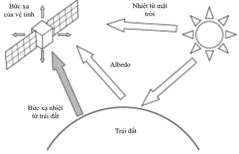
Figure 1.18. Main factors affecting satellite temperature
c) Radiation emitted by the earth
The heat that is absorbed from the sun but not reflected back as Albedo increases the temperature of the earth's surface and is then emitted as infrared energy. The earth's radiation output can vary depending on the specific temperature of a point on the earth's surface and the amount of cloud cover (more clouds reduce the earth's radiation received by satellites, but increase the reflectivity for solar radiation). In general, deserts in the tropics will have the highest earth's radiation coefficient and decrease with increasing latitude. The heat in the infrared region that the earth emits is equivalent to an object at a temperature of -18 o C, approximately
37
with a wavelength emitted by the satellite, much longer than the wavelength emitted by the sun at 5,500 o C. Unlike solar radiation, the earth's radiation cannot be reflected by the surface of the thermal management unit, because doing so would also prevent the heat emitted from inside the satellite from escaping the satellite (due to the same wavelength). Therefore, the heat emitted by the earth's surface will account for a large proportion of the increase in the temperature of the thermal management unit for satellites operating in low orbit.
It is worth noting that because the temperature of the satellite during operation is usually higher than the temperature of the earth, the heat will be transferred from the satellite to the earth, not the other way around. However, in the analysis process, people often ignore the presence of the earth, considering the entire 360 o around the satellite as space environment. Then the difference in infrared heat emitted and absorbed will be considered as the infrared heat emitted by the earth.
d) Friction with freely moving molecules (FHM)
This type of heating is caused by friction between the satellite and the freely moving molecules. For most satellites, FHM usually occurs during the satellite’s ascent when one of the fuel tanks is detached. The separation must be timed to reduce the unneeded mass as soon as possible but at the same time at a suitable altitude where the gas molecules are less dense to avoid overheating the satellite.
e) Thermal management methods for satellites
Thermal management for satellites is a matter of great concern in the process of designing and manufacturing satellites. To solve the problem of thermal management for satellites, people currently use many different technical methods. Thermal control techniques on satellites can be divided into active thermal control (ATC) and passive thermal control (PTC) [66]:
- PTC: does not involve any moving parts. The temperature of the satellite components can be kept within the appropriate operating range by controlling the heat released by the satellite components through thermal conduction. The advantage of this method is that it does not require additional power from the satellite, which is already quite limited in the total power output (through solar cells only). Furthermore, the passive thermal control method does not require any circuits or devices.
38
control, so the occupied volume of the satellite's internal system is small, not affecting the overall design of the satellite. However, the disadvantage of PTC is that it cannot operate in environments that are too harsh or for components that generate too much heat. Here are some passive thermal management devices for satellite thermal management:
+ Heat switches: Heat switches are devices that can change their thermal conductivity, meaning they can become good heat conductors or good insulators depending on the situation. When installed between the heat controller and the device that needs heat management, the change in the heat conductivity of the heat switch can be used to control the temperature of the device. Heat switches can be used to control the temperature of the device without using a heat controller, thus reducing the energy required during operation as well as the control circuit and software. During the manufacturing process, a default temperature will be assigned to the heat switch. When the temperature of the device that needs heat control exceeds this default temperature, the conductivity of the heat switch will increase, allowing the excess heat to pass quickly through the heat switch, go to the heat controller and out into the outside environment. Conversely, when the conductivity of the heat switch decreases, the device will be kept warm at an appropriate level by the heat generated by itself. There are usually two ways to install the thermal lock: one is to install it between the external thermal management unit and the satellite structure, and the other is to install it directly between the equipment and the satellite structure.
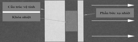
Figure 1.19. Description of thermal lock used in thermal management for satellites [66]
+ Phase Change Material (PCM): Devices used during launch or re-entry have a very short operating cycle and operate only once, but generate a lot of heat during operation. Therefore, for such devices, the requirement is that during long periods of inactivity and during periods of high heat generation,
39
temperature, the device must still be kept within the allowable operating range. The use of PCM will keep the device in a nearly isothermal state during satellite operation. The PCM will be alternately frozen and melted: when the device generates heat to heat the PCM, the PCM will now be in a frozen state and will change to a liquid state (constant temperature). During the time the device is not operating, the heat generated in the previous phase will be released by the thermal management unit and the PCM will return to a frozen state. Therefore, the device is always kept at a fixed temperature.
+ Heatpipe: Heatpipe can move a relatively large amount of heat from one point to another based on a two-phase cycle, thereby creating an isothermal surface. The structure of the heatpipe consists of a condenser, an evaporator and an adiabatic region. Both the liquid and gas solutions of the heatpipe are kept at saturation temperature. Because the heatpipe operates based on the capillary phenomenon, the wick can only provide a relatively small fluid force, so the heatpipe is not very effective in thermal management for the satellite. When heat is emitted (possibly from an operating device or due to long-term illumination from solar radiation), this heat will be transferred to the evaporator. Here, this heat will cause the liquid solution in the wick to evaporate, while increasing the gas pressure at the evaporator, causing the gas carrying heat to move from the evaporator to the condenser. In the condenser, hot gas when in contact with the cold surface will condense into a liquid solution, the heat generated in this process is transferred outside. The solution in the condenser through capillary phenomenon will return to the evaporator, thereby creating a closed cycle that does not need control.
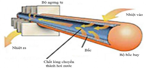
Figure 1.20. Operation mechanism of heatpipe in satellite thermal control [66]
40
- ATC: can overcome the disadvantages of PTC. ATC can use one of the devices such as heatpipe, louver, cooling/heating device or PFL.
Following are some active thermal management devices that serve the thermal management of satellites:
+ Louvers: Louvers are active thermal devices that have been widely used on satellites. In the fully open state, Louvers can release about 6 times more heat than when closed. Although they are active thermal control devices, Louvers do not require energy. Louvers are most suitable for satellites where the energy output of the devices varies greatly due to changes in the operating cycle. Today, Louvers usually include the following details: wing base plate, rectangular wings, bimetallic spring actuator, sensor, and bracket. Previously, there were two types of Louvers used: hydraulic and propeller type, but due to limitations in performance, they are no longer widely used. The wing base plate is a surface with a low absorption-to-emission ratio, used to cover satellite components that need temperature control. The wings are controlled by actuators, which change the thermal management capabilities of the Louvers. When the blades are closed, the blade base plate is protected and isolated from the outside environment, and when the blades are open, the base plate and the outside environment will be able to exchange heat with each other. The actuator controls the blade based on the temperature of the blade base plate. The actuator here is a bimetallic wire in a twisted form, which is able to contract when the temperature decreases and expand when the temperature increases.
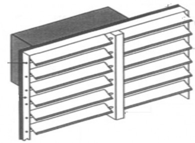
Figure 1.21. Vents used in thermal management for satellites [66]
+ Thermoelectric Coolers (TECs): TECs are a type of miniature pump that can cool devices that require low operating temperatures for a certain period of time. TECs are based on the Peltier principle, in which cooling is based on the movement of electric current through two different metal surfaces. These two surfaces are connected by two semiconductors, one p-type and one n-type, and heat is then pumped from the lower temperature metal surface to the higher temperature surface.
+ Pumped Fluid Loops (PFL): A space-based fluid loop typically consists of a pump, a heat exchanger, and a thermal management unit. The process is accomplished primarily by using a cooling water to manage the heat. This fluid absorbs the heat generated by the operating equipment and transfers it to the thermal management unit. There are two types of coolants used: reusable and non-reusable. For the non-reusable type, the fluid is ejected from the satellite after use. For the reusable fluid, the fluid is cooled, then returned to start the cycle once the heat energy has been transferred to outer space through thermal management.
Among the above methods, pumped liquid circulation (PFL) is a simple, accessible method and compatible with nanofluids with high thermal conductivity.
Currently, research on PFL systems in satellite thermal control is still being carried out, focusing on design improvements as well as research on new configurations. For example, in 2015, the research group of Roel C. van Benthem [67] developed a valve-free PFL system for large communication satellites. In 2016, the research group of Robert Thorslund (Sweden) developed a pump-based PFL system based on Electro Hydro Dynamic (EHD) technology with many superior properties [68]. Also in 2016, the research group of Ji-Xiang Wang (China) studied a highly adaptable cold plate for use in PFL systems [69]. Most recently, in 2017, the VS Jasvanth research group (India) studied the design and manufacture of a PFL system using ammonia for satellites with a capacity of up to 500 W [70]. However, the use of nanofluids with high thermal conductivity in PFL systems is still a new issue and has only been recently implemented by a few research groups.