0
- Subsidence stress at the bottom of element layers:
i
oh
gl k
In there:
. gl
+ Ratio: L qu /B qu = 4.69/3.39 =1.4
0
+ gl
=24.62T/m2 : is the settlement stress at the bottom of the conventional foundation;
+ k 0i : is the stress coefficient at the center of the rectangle (L qu /B qu ; 2z i /B qu ) looking at table 2.1 we have the subsidence stress at the bottom of the element layers:
Table 3.16: Calculation table of self-stress and settlement stress
STT
h i (m) | z i (m) | 2.z i /B m | γ i (T/ m3 ) | σ i bt (T/ m2 ) | k 0i | σ i gl (T/ m2 ) | P i (T/m 2 ) | σ i bt / σ i gl | |
0 | - | - | 32.94 | 1,000 | 24.62 | ||||
1 | 0.678 | 0.678 | 0.40 | 1.95 | 34.26 | 0.972 | 23.93 | 24.28 | 1.43 |
2 | 0.678 | 1,356 | 0.80 | 1.95 | 35.58 | 0.848 | 20.88 | 22.40 | 1.70 |
3 | 0.678 | 2,034 | 1.20 | 1.95 | 36.91 | 0.682 | 16.79 | 18.83 | 2.20 |
4 | 0.678 | 2,712 | 1.60 | 1.95 | 38.23 | 0.532 | 13.10 | 14.94 | 2.92 |
5 | 0.678 | 3,390 | 2.00 | 1.95 | 39.55 | 0.414 | 10.19 | 11.65 | 3.88 |
6 | 0.678 | 4,068 | 2.40 | 1.95 | 40.87 | 0.325 | 8.00 | 9.10 | 5.11 |
7 | 0.678 | 4,746 | 2.80 | 1.95 | 42.19 | 0.260 | 6.40 | 7.20 | 6.59 |
Total | 108.40 |
Maybe you are interested!
-
 Slope calculation with crushed stone foundation structure.
 -
 On the Issue of “Gia Long Phuc Quoc” (Restoring the Foundation)
 -
 Programming Foundation - University of Commerce - 1
 -
 Programming Foundation - University of Commerce - 10
 -
 Research Model of Factors Impacting Work Motivation of Tour Guide Team in Binh Dinh Province

e) Check the subsidence stop condition
- Depth z 7 = 4.746m we have:
7
7
bt 42.2T / m 2 5 gl 5.6.4 32.0T / m 2
- So stop calculating settlement at depth Z 7 = 4.746m.
f) Determine total settlement and check settlement
- The final (stable) settlement is determined by the following formula:
n
S i ph
E
ii
i 1 oi
S 0.8 .0.678.108.4 = 0.0784
750
S = 7.84m
- Check for subsidence:
S = 7.84 cm S gh = 10cm (Satisfied) In which:
+ h i =0.678m: is the thickness of the i-th element soil layer;
i;
+ pi : is the average subsidence stress of the i-th element layer;
+ i = 0.8 for all soil layers;
+ E 0i = 75 kg/cm 2 = 750T/m 2 : is the total deformation modulus of the soil element layer
- So with the selected foundation and pile size, the allowable settlement conditions are satisfied.
Q tt
N tt
0
0M 0
tt
h m = 2000
3.2.9 Determine the working height of the foundation
45°
H m
a
45°
P 1 =P 2 P 3 P 4 =P 5 P 6 P 7 =P 8
x
L x t = 2600
300
650
1 4 7
B x t = 1900
b c
B m = 1900
3 6 years
650
l c
300
2 5 8
300 650
650
650
650
300
L m = 3200
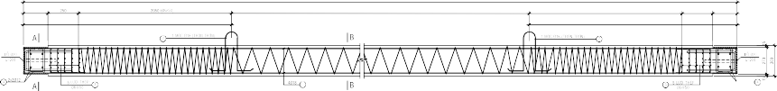
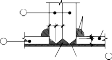
Figure 3.20: Calculation and puncture test diagram
3.2.9.1 Determine the minimum height of the foundation
- Minimum height of foundation: H min = 2d+a = 2,300+100 = 700
In there:
+ d =300: is the edge of the pile;
+ a = 100: is the pile section attached to the foundation.
- Choose H m = 1.1m ≥ H min
=> H 0 = H m - a = 1.1 - 0.1 = 1.0m
3.2.9.2 Check height H m under puncture condition
- Penetration tower size:
B xt = b c + 2H 0 = 0.4 +2.1.0 = 2.4m > B m => B xt = B m =1.9m L xt = l c + 2H 0 = 0.6 +2.1.0 = 2.6m
- Force causing penetration:
N gxt
n
i
P tt (outside the penetration tower)
i
- We see: The penetration tower covers the center of all piles. Therefore, we do not need to check for penetration.
3.2.10 Steel calculation
3.2.10.1 Select foundation material
- Choose concrete grade 300 with:
+ R b = 130 kG/cm 2 = 1300 T/m 2
+ R bt = 10 kG/cm 2 = 100 T/m 2
- Select AII load-bearing steel with:
+ R s = R sc = 2800 kg/cm 2
3.2.10.2 Calculation of reinforcement according to the side direction L m
- Bending moment in direction L m :
n
M (y l c )P tt
2
L iii 1
M L = 2.62.4.(0.65 0.6 ) 2.64.7.(1.3 0.6 ) 92.61 Tm
2 2
- Steel reinforcement calculated according to L m direction :
A tt M L
92.61.10 5
= 36.75 cm 2
sL 0.9R
s H 0
0.9.2800.100
- Steel structure according to L m direction :
A
ct
sL min
.BH 0
= 0.1%.190.100 = 19.0 cm 2
- Arrange the steel in the lower region according to the L m direction :
A
SL
sL
d max(A tt
; A ct ) = 36.75 cm 2
SL
+ Choose steel 20 with f a = 3.14 cm 2
A d 36.75
+ Number of steel bars: n dL =
sL = 11.7 trees => Choose n dL = 12 trees
n
1
f a 3.14
+ Reinforcement step: @
= B m 100 1900 100 = 164
dL
dL
12 1
=> Select @ dL =160
+ So the steel is arranged in the direction of edge L in the lower region: 20@160
- Arrangement of structural steel in the upper region according to the L m direction :
A
A
t ct
sL SL
= 19.0 cm 2
+ Choose steel 14 with f a = 1.54 cm 2
At 19.0
+ Number of steel bars: n tL =
sL = 12.3 trees => Choose n tL = 13 trees
f a 1.54
+ Reinforcement step: @
= B m 100 1900 100 = 150
tL
tL
13 1
n
1
+ So the steel is arranged in the direction of edge L in the upper region: 14@150
3.2.10.3 Calculation of reinforcement according to side direction B m
- Bending moment in direction B m :
n
M (x b c )P tt
2
B iii 1
M B = (55.5 60.1 64.7).(0.65 0.4 ) 81.14 Tm
2
- Steel reinforcement calculated according to B m direction :
A tt MB
81.14.10 5
= 32.20cm 2
sB 0.9R
s H 0
0.9.2800.100
- Steel structure according to direction B m :
A
ct
sB min
.L m
.H 0
= 0.1%.320.100 = 32 cm 2
- Arrange the steel in the lower region according to the B m direction :
A d max(A tt ; A ct )= 32.20 cm 2
sB sB sB
+ Choose steel 16 with f a = 2.01 cm 2
A d 32.20
+ Number of steel bars: n dB =
sB = 16 trees => Choose n dB = 16 trees
f a 2.01
+ Reinforcement step: @
= L m 100 3200 100 = 207
dB
=> Select @ dB =200
n dB 1 16 1
+ So the steel is arranged in the direction of edge B m in the lower region: 16@200
- Arrangement of structural steel in the upper region according to direction B m :
A
sB
sB
t A ct =32.0 cm 2
+ Choose steel 14 with f a = 1.54 cm 2
A t 32.0
+ Number of steel bars: n tB =
sB = 20.8 trees => Choose n tB = 21 trees
f a 1.54
+ Reinforcement step: @
= L m 100 3200 100 = 155
tB
=>Select @ tB = 150
n tB 1
21 1
+ So the steel is arranged in the direction of edge B m in the upper region: 14@150
3.2.11 Drawing representation
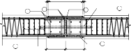
- Foundation drawing: Figure 3.21
- Pile drawing: Figure 3.22

Column steel
NATURAL GROUND
Tripod
4 ị14a150 ị14a150 3
5
2 in 12
Concrete foundation stone 40x60 grade 100
1 ị20a160 ị16a200 2
SECTION AA
TL:1/25
ị14a150 3

AA
ị14a150 4
ị16a200 2
B
ị20a160 1

* STONE CONCRETE 10X20 GRADE 300 (DURABILITY LEVEL B22.5)
* STEEL < 10 .Rs = 2250 kg/cm2 (AI STEEL)
* STEEL >= 10 .Rs = 2800 kg/cm2 (AII STEEL)
NOTES :
2
FOUNDATION PLAN
TL:1/25

Ho Chi Minh City College of Construction
300
SECTION P2
8300
CONNECTION SEE DETAILS

16.6M PILE DIAGRAM
SECTION P1

Foundation design guide
8300
200
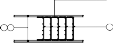
Figure 3.22 Pile design drawing
250
2500
2050 (Þ6/50)
8300
3300 (Þ6/150)
8
DETAILS OF PILE SECTION P2
2050 (Þ6/50)
2500
250
200
2x2ị12
A
HOLE20
125 125
300
2Þ1 4 1 MeC ị16 (SMOOTH) 7
4 2x2ị12A
3
5 STEEL MESH Þ6@50
4Þ18
DETAILS OF PILE SECTION P1
20 360 20
9
L 63x63x6 L=360
15
DIG A 50x50 HOLE ON 1 SIDE OF THE PILE TO COMPACT THE CONCRETE AT THE HEAD OF THE PILE

9
L 63x63x6 L=360
-190x8
-190x85
8
254
270
254
10 -280x10
280
FACTORY WELDING
5 5
-190x8
WELDING STEEL MESH TO LONGITUDINAL STEEL OF PILES
4Þ18 5 STEEL MESH 3
5 -190x6
254
8
25
4Þ124
300


5 2
250
2 5
8
WELDING JOINT EDGE Hh=8
250
300
60 50
5 254
5
4 2
-190x8 254
WELDING JOINTSANGLE STEEL
254 5 1 8
Þ6@50
1 8 4Þ18
WELDING TO PLATE
-190x208x6
1 4Þ18
200
110 50 110
15 270
300
8
200
254 8
270
L 63x63x6 9
STEEL MESH WELDING DETAILSINTO STEEL CHU Û
8 254
270
8 JOINT EDGE WELDING
Chapter 3: Pile foundation design
8 254
270
25
SPIRAL BELT 62
@ 50-150
DETAILS 1
DETAILS OF THE PASSAGE OF NO CATHOLIC 1-1
11 2Þ1 4
11 2Þ1 4
300

420
125 50 125
AA CAFEBB CUT
- PILE 300x300, L=16.6M
- STONE CONCRETE 10x20; GRADE 300 (DURABILITY LEVEL B22.5)
- LOW BONE: ị<10 Rs=2250KG/CM2. (AI)
ị >=10 Rs=2800KG/CM2. (AII)
- DESIGN LOAD Ptk = 70.5T
- TEST PILES ACCORDING TO TCVN 9393:2012,
2-CYCLE TEST, MAXIMUM TEST LOAD LEVEL 2Ptk.
- WELD STRENGTH Rgh>=1700 KG/CM2.
- WELDING ENTIRE CONTACT LENGTH, Hh>=6MM.
NOTES
10
420
20
10
-270x10
Page | 103
4 2x2ị12 270
5 STEEL MESH
360
20
9
L 63x63x6 L=360
Hole 20 x 18, L=590
12
30 210 30
210
30
30
30
210
-190x85
-270x10 270
10 -270x10
30 210 30
125 50 125
300
270
HOLE20
218

218
50
30
LOW GRID 6a50
1Þ20
LOOK CC
3 Þ6@50
200
200
254
PILE CAP DETAILS
CUT 2-2PILE CAP DETAILS
(PILE CONNECTION)
INDEX
MISSION 2
IMPLEMENTATION OF FOUNDATION PROJECT 2
Code 4
SINGLE FOUNDATION DESIGN SECTION 4
CHAPTER 1 14
GENERAL INSTRUCTIONS 14
1.1 IMPLEMENTATION CONTENT 14
1.2 CALCULATION DESCRIPTION REQUIREMENTS 14
1.3 DRAWING REQUIREMENTS 17
CHAPTER 1 DESIGN OF SHALL FOUNDATIONS 18
2.1 SINGLE FOUNDATION CALCULATION DESIGN PROCEDURE 18
2.1.1Determine the load on the foundation 18
2.1.2 Assessment of hydrogeological conditions 18
2.1.3Determine foundation depth 18
2.1.4 Determining the preliminary dimensions of the foundation 19
2.1.5 Checking the stress under the foundation 22
2.1.6 Calculation and settlement testing 23
2.1.7 Determine the working height of the foundation (Hm) 29
2.1.8 Calculation of reinforcement 32
2.2 SINGLE FOUNDATION DESIGN CALCULATION EXAMPLE 34
2.2.1Determine the load on the foundation 35
2.2.2 Summary of hydrogeological conditions 35
2.2.3 Choosing the depth of foundation 35
2.2.4 Determine the preliminary size of the foundation 36
2.2.5 Checking stress under the foundation 37
2.2.6 Calculation and settlement testing 38
2.2.7 Determine the working height of the foundation 40
2.2.8 Calculation of reinforcement 42
2.2.9 Drawing representation 45
Chapter 3 PILE FOUNDATION DESIGN 46
3.1 DESIGN PROCEDURE FOR LOW PILE FOUNDATION 46
3.1.1Determine the load on the foundation 46
3.1.2 Assessment of terrain, geology and hydrology conditions 46