The pipes of the cooling tank, between the pipes there is an air flow drawn by the fan 13, the water is cooled and pumped into the water jacket.
To cool the parts evenly, the grooves direct the water flow first to the hottest parts, then to the remaining parts. The high speed of water movement creates conditions for even cooling, ensuring forced circulation, thanks to which the difference in water temperature at the engine inlet and the engine outlet does not exceed 8 0 C.
To keep the thermal state of the engine unchanged (independent of load and working conditions), people use thermal valve 3 (Figure 1.1).
To warm up the engine after starting or to prevent the engine from cooling too much in cold weather, a curtain 15 (figure 1.1) is placed in front of the radiator 14, which is a wind shield, and has the effect of regulating the amount of air passing through the radiator.
An open forced cooling system is one in which the upper compartment of the radiator (cooling tank) is open to the outside air. An engine with an open system loses a lot of water and the water evaporates and overflows. The water evaporates in the system, creating water stains that are difficult to clean.
Maybe you are interested!
-

 Working Principle Diagram Of Continuous Butter Making Equipment
 -
 System of Methods and Works for Biological Treatment of Wastewater Based on Oxidation Principle.
 -
 Some Algorithms Working With Inode System File System Calls
 -
 Working Principle of Variable Displacement Compressor
 -
 Function, Mode and Working Principle of the Meter:
A closed forced cooling system is one that is not directly connected to the air. If the system is closed, when the engine is hot, the steam pressure can burst the radiator pipes and when the engine cools down after being turned off, the steam in the radiator condenses, causing a drop in pressure that can also damage the pipes. To overcome this situation, the radiator is equipped with a vent valve, which keeps the pressure in the radiator from increasing or decreasing too much.
1.2 Hybrid cooling system
In large tractor engines using a starter motor, the cooling system is often of a mixed type (Figure 1.1). When the starter motor is running until the main engine crankshaft starts rotating, the water will circulate according to the convection principle (thermosiphon). Such a thermosiphon circulation occurs when the starter motor is heated. The hot water in the water jacket 8 moves up
above and through pipe 7 enters the water jacket 5 of the main engine and replaces it with coolant that goes from the distribution groove 10 through pipe 9 into the water jacket 8 of the starter motor. Then the cover and cylinders 6 of the main engine heat up, making starting easy.
During the main engine operation, water will be forced to circulate in the cooling system thanks to the centrifugal water pump 11.
1.3 Working principle of air cooling system
In engines with air cooling, the cylinders and cylinder heads are cooled by air. To increase the cooling surface, the cylinders have fins 19 (fig. 1.1,b). The fins 16 push the cooled air into the cavity inside the casing 17, pass through the space between the cylinder fins and the cover, cool them and blow them through the ports 21. Thanks to the constricted casing and the guide plates 20, the air is evenly blown into the cylinders from all sides.
The air-cooled system has a simpler structure than the liquid-cooled system, without a radiator or connecting pipes, so the engine size and weight are smaller. Maintaining an air-cooled engine is also simpler because there is no need to monitor the water level or tightness at the joints. However, the thermal stress of an air-cooled engine is greater than that of a water-cooled engine because air conducts heat from the parts less well than water. The engine operates noisily because there is no soundproofing part, the water jacket.
1.4 Structure and operation of components
1.4.1 Water pump
The water pump used in the cooling system is a centrifugal pump. This type of pump allows to create a large flow with moderate pressure.
On the engines, the water pump is manufactured in a common assembly with the impeller. The body 2 (figure 1.2,a and b) of the water pump is bolted to the front wall of the engine block through a sealing gasket. In the pump body there is a shaft 8 placed on 3 ball bearings 10. On the rear end of shaft 8 is installed the pump impeller 1 placed in the water-filled compartment of body 2. When the pump impeller rotates, due to centrifugal force, water will be thrown into
Discharge chamber. The discharge chamber is expanded in a spiral shape in the direction of rotation of the pump impeller, so the speed of water entering here decreases, while the pressure increases. The maximum pressure zone B is opposite the water distribution groove K of the cylinder block, from here the water is pushed.
As the water comes out from between the blades, a vacuum appears in the center of the pump (area C), causing water to continuously flow from the suction chamber into this chamber, which is connected to the lower tank of the cooling tank by pipes and rubber hoses.
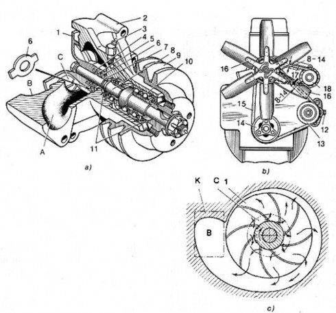
Figure 1.2. Water pump (a), drive part (b) of impeller and water pump, operating diagram of centrifugal pump (c)
1-water pump; 2-body; 3-grease nipple; 4-rubber cover; 5-spring; 6-washer; 7-bearing; 8-shaft; 9-pulley; 10-bearing; 11-grease shield; 12-belt roller bolt; 13-tension roller; 14-crankshaft pulley; 15-fan and water pump ladder belt; 16-fan; 17-generator ladder belt; 18-generator; A-suction chamber; B-maximum pressure zone; C-vacuum zone; K-water distribution groove.
The shaft bearings are lubricated with solidon grease, pumped through grease nipple 3. Depending on the level of grease loaded into the bearing cavity, air from here will escape through the hole in the pump body. When grease flows out of this hole, it proves that lubrication is sufficient. Grease seals 11 prevent grease from entering the gap between the shaft and the body.
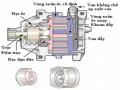
1.4.2 Propeller
The fan blades are responsible for creating a high-speed air flow through the radiator for cooling. Usually it is placed right behind the radiator, the amount of air passing through the radiator depends on the span of the blades, the number of blades, the angle of the blades and the rotation speed of the fan.
The fan blade is located at the rear of the radiator, inside there is a housing attached to the radiator. Pulley 9 is attached to the front end of the shaft with a key and nut, the fan blade fork 16 is attached to the end face of the pulley. Pulley 9 receives rotation from the crankshaft pulley 14 through the escalator belt 15. When the fan blade is working, a vacuum is created inside the housing to suck cold air through the radiator core.
In some engines, the fan is mounted on the front wall of the engine block. Its pulley receives rotational motion from the crankshaft pulley by means of trapezoidal belts. The pulley is connected to the fan shaft not by a rigid connection but by a hydraulic clutch. The fan shaft is connected to its driven part, the number of revolutions of which depends on the amount of oil from the engine lubrication system that enters the clutch through an engagement device.
When the engine is cold, the drawer of the engagement part, controlled by a temperature sensor, will close the oil path to the clutch. Therefore, the pulley together with the active part of the clutch will rotate smoothly without transmitting motion to the fan blade (only rotates slightly due to friction in the clutch). Depending on the heat level of the engine, the drawer is moved and when it reaches a temperature of 90 0 C, it opens to let oil enter the hydraulic clutch, resulting in the fan blade being engaged. If the temperature of the coolant drops to 75 0 80 0 C, the fan blade is separated again. Thus, the thermal state of the engine is automatically adjusted.
1.4.3 Radiator
The main parts of the engine radiator are made of copper, which has high thermal conductivity, sufficient strength and better corrosion resistance than steel. The radiator consists of 9 upper barrel cores 7 and 19 lower barrel cores made by stamping method.
The core is made up of rows of flat oval tubes, which are inserted through thin horizontal plates to increase the cooling surface. The ends of the tubes are welded to thick outer plates called tube boards, which slightly protrude from the board. The tank is attached to the tube boards by rubber gaskets, in which steel plates are placed under the bolts and under the nuts to increase the stiffness of the joint.
To contain cooling water and cool the water. The radiator consists of an upper compartment, a lower compartment and a radiator core consisting of many pipes, the outside of which has radiator fins. The ends of the pipes are welded to a thick plate, the thick plate is tightly attached to the compartments with gaskets to seal the upper compartment has a water inlet, a tube to install a rubber pipe to lead water from the water jacket. The lower compartment also has a tube to install a rubber pipe to lead water to the water pump.
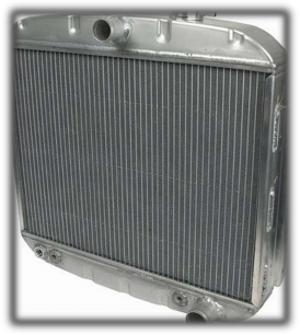
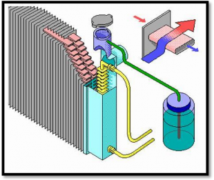
Figure 1.3 Car radiator
The radiator is attached to the front beam of the frame through a rubber shock absorber 21. The upper end of the radiator is attached to the cylinder block cover by tie rods. In the upper tank of the radiator there is a water filling neck with a cap 3. The length of the filling neck is quite large.
Prevents additional cold water from entering the system through the rubber hose 32 into the hot engine water jacket. This prevents the cylinder head from cracking.
In the manifold flap there is a steam-air valve. When the flap is placed on the manifold, the steam valve 4 (figure 2.4) is pressed against the flange of the manifold 2 by a spring 7 through a rubber gasket 3, separating the upper chamber flap from the atmosphere.

Figure 1.4 Water filling neck cap
1-air valve; 2- radiator neck; 3- gasket; 4- steam valve; 5- cover; 6- push rod; 7- spring; 8- exhaust pipe.
Between the steam valve there is a hole covered by the rubber air valve 1. When the pressure in the system is greater than the atmospheric pressure by 0.028 0.033 MPa, the steam valve 4 overcomes the resistance of the spring and is moved up along the push rod. Steam passes through the gap into the neck cavity and continues to flow out through the pipe 8. If the steam is condensed when the engine is cold, a vacuum will appear in the system, and air will flow from the neck cavity through the air valve into the cooling tank.
The radiators of other tractor engines are basically similar in structure to the radiators just presented, differing mainly in dimensions and mounting methods.
1.4.4 Thermostat valve
The thermostatic valve opens and closes different water lines to allow the coolant to circulate in a suitable cycle (through the radiator or not) depending on the engine's temperature.
The structure of the thermostatic valve is shown in Figure 2.5. All the details of the thermostatic valve are made of copper. The elastic thin-walled box 4 is a folding lamp.
cylindrical, it is stamped together with the blade 7 and is connected to the rim 3 through the lower cover 5. The hollow rod 1 is welded to the upper cover of the spring box, the central valve 9 is screwed to the threaded end of the rod 1. The side valves 2 and 6 are also welded to the upper cover. A little light volatile liquid is poured into the compressed spring box through the hole drilled in the rod 1. Then the hole in the rod is plugged with a ball 8 and welded, thereby keeping the box in a compressed state.
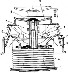
Figure 1.5 Thermostat valve
1-rod; 2 and 6-side valves; 3-ring; 4-rebound box; 5-bottom cover; 7-blade; 8-ball; 9-center valve.
When the water temperature increases, the liquid in the elastic box 4 evaporates, the pressure in it increases, the box expands and the central valve 9 opens. At the same time, the side valves 2 and 6 close the hole in the rim.
The thermostatic valve is located in a removable body 30 (see figure 1.5), the lower edge of the ring being squeezed between the upper and lower halves of the body. The upper opening of the thermostatic valve ring is located in the opening of the connecting part, separating chambers A and B of the thermostatic valve body. Chamber A communicates with the upper tank 7 of the radiator, chamber B communicates with the suction chamber of the water pump 13 (by means of a rubber tube 12), and chamber C communicates with the water jackets 25 of the cylinder head and the water jacket 27 of the starter motor (by means of a tube 29).
When the engine starts hot, thermosyphon circulation occurs in the system.
Hot water in the water jacket 27 of the starter motor rises through pipe 29.
and the groove D of the body 30 enters the chamber C which communicates with the water jackets 25 of the cylinder head and the tube 26 returns to the water jacket 27 of the starter motor.
When the diesel engine is running, as well as when it is rotated by the starter motor, forced circulation of water occurs in the system. The water pump 13 pushes water through the water distribution groove 14 and the holes 22 to cool the engine.
From the engine cover block, water enters chamber C of the body 1 of the thermostat valve. The next water path will depend on the water temperature. If the water temperature is below 70 0 C, the hole of the thermostat valve ring is closed by the central valve, and the side ports are opened. Therefore, the water does not enter the radiator but goes through the side ports into chamber B along groove D, the rubber tube 12 flows into the suction chamber of the water pump and is pushed into the water jacket and the engine will heat up quickly.
When the water temperature is higher than 70 0 C, the central valve of the thermostat opens, the doors on its rim are closed by the side valves. Water from chamber C flows into chamber A and continues through pipe 32 into the upper tank 7 of the radiator, through the pipes of the radiator down to the lower tank 19, then returns to the suction pipe 20 of the cooling water pump.
At a temperature of 83 0 C the central valve of the thermostatic valve is fully open and all the water flows through the radiator. At a temperature below 83 0 C the side valves do not completely close the ring ports, so part of the water flows to the water pump without going through the radiator. Check the thermal condition of the engine with a thermometer, the sensor of which is screwed into the upper tank of the radiator, and the dial 2 is mounted on the dashboard.
1.5 Common failures and repairs in the cooling system
1.5.1 Water pump failure and repair
Water pumps often have the following main damages: mainly due to worn and bent shafts, bearings, broken impellers, pitting, cracked casings, and damage to sealing parts.
Repair the broken flange and the crack on the body by welding. The part is preheated and then welded with a neutral oxyacetylene flame. Cracks can be patched with epoxy glue. When checking, if the water pump shaft is bent, bend it on the press. If the shaft is slightly worn, restore it by chromium plating and then grind it to the required size. If the shaft is heavily worn, it can be welded and then reinforced.