2.4. Self-study guide:
1. Calculate the basic parameters for milling a left-handed helical gear with module m = 2.5, number of teeth Z = 17, α = 15 ° .
2. Calculate the basic parameters for milling helical gears with helical direction with module m = 1.75 number of teeth Z = 29, α = 17 ° .
LESSON 06: SPEED SHAFT MILLING
6.1 Milling of spline shaft with three-cutting disc milling cutter
Time to complete: 6 periods Previous lesson name:
................................................................ .
Performed from date..................... to date ....................................
I. Teaching facilities and equipment
1.1. Means:
Lesson plans, outlines, chalk, projector, drawings, ...
1.2. Equipment:
T
T
Name and specifications of the device, tools; raw materials, consumables | Single taste | SL | Note | Additional | |
1 | Device | ||||
Universal milling machine 6X332B | Female | 07 | Continued use | ||
Spare parts for milling machine | Set | 07 | Continued use | ||
2 stone grinder | Female | 01 | Continued use | ||
Universal indexing head | Female | 07 | Continued use | ||
Universal indexing head spare parts | Set | 07 | Continued use | ||
2 | Tool | ||||
Dial gauge + holder | Set | 05 | Continued use | ||
Caliper 1/50, L=200 | Female | 07 | Continued use | ||
Wrench set from 8÷24mm | Set | 05 | Continued use | ||
3 | Materials (for 01 student) | ||||
Steel billet Ф42, L=220 | Female | 01 | Continued use | ||
Cutting tool: 3-sided disc milling cutter Ф63x5 | Son | 01 | Continued use | ||
Cutting tool: 3-sided disc milling cutter Ф63x8 | Son | 01 | Continued use | ||
Cleaning cloth | Kg | 0.2 | Cancel | ||
Paint brush | Female | 1 | Continued use | ||
HD50 Oil | Liter | 0.5 | Cancel | ||
4 | Other |
Maybe you are interested!
-

 Study on the influence of some factors on specific energy cost and surface roughness when milling flat surfaces with face milling cutters on milling machine TUM 20VS - 1
 -
 Some Key Solutions to Promote Positive Changes and Limit Negative Changes of Socialist Production Relations in
 -
 Some Theories on Industrial Development in Key Economic Regions
 -
 Key Solutions to Strengthen the Leadership of Hai Phong City Party Committee in Security and Order Work by 2030
 -
 Results After Creating Foreign Key Constraints and Foreign Keys
II. Lesson implementation
2.1. Lesson objectives
After completing this lesson, students will be able to:
+ About knowledge:
- Master the method of milling spline shafts with 3-cutting disc milling cutter
+ About skills:
- Perform the processing steps in the correct order to mill the spline shaft with a 3-cutting disc milling cutter to meet technical and time requirements;
+ About attitude:
- Serious and proactive in learning and practicing industrial production style.
- Ensure labor safety and environmental hygiene.
2.2. Lesson content
2.2.1. Characteristics of spline shaft
The spline shaft has the function of transmitting torque and motion to the gears. The gears slide on the shaft thanks to the lever. The lever acts on the gears to change the position of the gears, thereby changing the output speed of the gearbox. The spline shaft is commonly used with the sliding gears of the gearboxes of universal milling machines, lathes, etc.
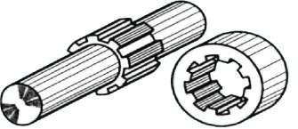
Figure 6.1.1: Basic parameters of spline shaft
Basic parameters of spline shaft:
- Top circle diameter: D
- Foot circumference diameter: d
- Tooth height: H
- Tooth width: B
2.2.2. Technical requirements for spline shaft
- Dimensional accuracy: D, d, B, H
Depending on the centering method between the spline shaft and the spline sleeve, the required dimensional accuracy is different.
- Tooth profile accuracy
- Sufficient number of spline shaft teeth
- Surface roughness of tooth flank Rz20
2.2.3. Select cutting mode:

Cutting mode is calculated according to the material of the cutter and the processing material. Normally, high-speed steel cutters have a cutting speed of V = 20 ÷ 40m/min. The way to choose cutting mode parameters is the same as when milling straight grooves with a disc milling cutter.
three sections
2.2.4. Implementation sequence
Step 1: Calculate the grading
N
n tq Z
Depending on the number of teeth to be machined Z
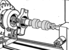
Step 2: Fixture and mount the workpiece onto the machine
Figure 6.1.3: Position adjustment
The spline shaft machining fixture is the head
Figure 6.1.2: Milling fixture for spline shaft
Universal indexing fixture fixture process is similar to that of milling spur gears.
The workpiece is clamped at one end into the 3-jaw chuck of the indexing head, the other end against the tailstock center of the indexing head or both ends against the center transmitting the torque by the clamping speed as shown in Figure 6.1.2.
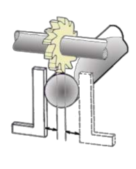
Step 3: Knife holder
Determine the exact position of the milling cutter on the mandrel and check the runout of the milling cutter.
Step 4: Adjust the position of the blank knife, get the cutting depth
square tool holder
Turn on the main shaft to touch the top surface of the workpiece, then move the knife away from the workpiece to get the cutting depth T = H + 0.5. Turn off the main shaft, use a square bracket with one edge against the machine table surface and the other edge against the side of the workpiece, so that the side of the knife
Touch the square then move the knife out of the workpiece in the axial direction and move it towards the center of the workpiece by an amount
L D B
2 2
Step 5: Cut the first tooth flank of the teeth
After adjusting the blank knife and taking the cutting depth as in step 4, we proceed to remove the indexing head dirt.
Turn on the machine to cut the first tooth flank of the first tooth to the required length, then return the cutter to the original position and perform the n=N/Z division to mill the first tooth flank of the second tooth. Do the same until all the first tooth flanks of the teeth are milled.
Step 6: Cut the second tooth flank of the teeth
After cutting all the first tooth flanks of the retracted teeth to their original position, move the knife past the center of the workpiece by an amount L = B tooth + B knife to cut the second tooth flank of the first tooth to the full machining length. Then retract the knife to its original position and perform the n=N/z division to cut the second tooth flank of the second tooth. Do the same until all the second tooth flanks of the teeth are milled.
Step 7: Milling to achieve tooth root radius
Figure 6.1.4: Cutting the first tooth flank of the teeth
Figure 6.1.5: Cutting the second tooth flank of the teeth
After finishing the two tooth flanks, proceed to machine the tooth root diameter by choosing a small-width disc milling cutter so that the cutter angle does not cut into the tooth flank. Move the cutter to the center of the workpiece, lower the machine table 0.5mm compared to when milling the tooth flanks to reduce the concentration of tooth root stress, turn the indexing head to bring the center of the groove to coincide with the center of the cutter as shown in Figure 6.1.6
After each cut, rotate the workpiece at a small angle to cut off all excess machining to create the radius of the foot.
Note: Adjust the milling cutter and indexing head so that the cutter does not cut into the tooth flank.
Do the same with the next tooth grooves until tooth z. The details will be as shown in figure 1.1.7
Figure 6.1.7: Details after machining
Figure 6.1.6: Milling to achieve tooth root radius
Step 8: Finish
2.2.5. Types of failures, causes and prevention
TT
Damaged form | Reason | Prevention | |
1 | Number of teeth on the flower shaft incorrect | Calculate the error | Calculate the exact division before processing |
2 | Wrong size | - Due to incorrect calculation of knife translation - Due to incorrect adjustment of the machine travel chain - Wrong measurement | - Accurate tool displacement calculation Review machine travel line value - Reinforce measurement operations |
3 | Tooth profile not satisfactory | - Due to uneven blade wear - Wrong classification | - Sharpen or replace the knife. - Main grading operation body |
4 | Tooth flank roughness not achieved | - Dull knife. - Improper cutting mode -Low stability technology system | - Sharpen or replace knife - Reselect cutting mode - Tighten the levers to prevent unnecessary movements. |
2.3. Organizing skill training
1. Practice requirements:
a. Drawing
63x8
b. Practice requirements:
Machining spline shaft with Z = 6, B = 8, H = 5. Select 3-facet disc milling cutter 63x5 and
Requirement: 2 students/1 product
2. Implementation steps
TT
Steps to take | Instructions for implementation | |
1 | Step 1: Calculate the grading n N 40 6 20 tq Z 6 30 | After milling one tooth side, mill the second tooth side by turning the indexing head 6 times. and 20 holes on the 30 hole ring |
2 | Step 2: Fixture and mount the workpiece onto the machine | Fixture the workpiece center parallel to the longitudinal cutter travel direction and parallel to the machine table surface. Mount one end on the three-jaw chuck of the indexing head, one end against the center or mount on two heads |
Step 3: Mount the 63x8 disc knife on the horizontal axis
| Determine the exact position of the milling cutter on the mandrel and check the runout of the milling cutter. | |
4 | Step 4: Adjust the position of the blank knife, get the cutting depth
| Turn on the main shaft to touch the knife on the top of the workpiece, then move the knife away from the workpiece to get a cutting depth of T = 5.5mm. Turn off the main shaft, use a square bracket with one side pressed against the machine table, the other side pressed against the side of the workpiece, let the side of the knife touch the square bracket, then move the knife away from the workpiece in the axial direction and move it to the center of the workpiece by an amount L D B 39 8 15.5 2 2 2 2 |
5 | Step 5: Cut the first tooth flank of the teeth n = 200 rpm; t = 5.5mm ; S =40mm/min | Turn on the machine to cut the first tooth flank of the first tooth to the full length required to be machined, then return the cutter to the original position and perform the division as in step 1 to mill the first tooth flank of the second tooth. Do the same until all the first tooth flanks of the 6 teeth are milled. |

3
Step 6: Cut the second tooth flank of the teeth n = 200 rpm; t = 5.5mm; S = 40 m/min | After cutting all the | |
first tooth ridge of the | ||
teeth retract knife to original position, | ||
move the knife through the center of the workpiece one | ||
amount L = 8 + 8=16mm advance | ||
Second tooth cutting | ||
of the first tooth all the way | ||
machining length. Then retract the knife | ||
back to original position | ||
division as step 1 milling | ||
second ridge of tooth | ||
second. Do the same until | ||
when all tooth flanks are milled | ||
second of 6 teeth. | ||
7 | Step 7: Milling to achieve tooth root radius
n = 300 rpm; t = 5mm; S = 80mm/min | After finishing the two tooth flanks, proceed to machine the tooth root diameter. Replace the 63x8 disc milling cutter with a 63x5 cutter. Move the cutter to the center of the workpiece, lowering the machine table 0.5mm compared to when milling the tooth flanks to reduce the concentration of tooth root stress, turn the indexing head to bring the center of the groove to coincide with the center of the cutter. After each cut, rotate the workpiece at a small angle to cut off all excess machining to create the radius of the foot. |
8 | Step 8: Finish | Check the root diameter and tooth height as well as observe the evenness of the tooth peaks. |