3.3.3. Interaction of oseltamivir with influenza A/H3N2 viruses
The results of the NAI test performed on 157 A/H3N2 virus strains showed that the IC 50 value of H3N2 strains ranged from 0.038 - 0.29nM, no virus was detected with a value exceeding the threshold value (0.164nM) by 10 times or more (according to the result assessment table). Table 3.5 shows the IC 50 value of H3N2 virus by year. This result allows to confirm in this study that influenza A/H3N2 virus circulating in Vietnam during the period 2003 - 2012 responded well to the antiviral drug oseltamivir.
Table 3.5. IC 50 values of A/H3N2 strains from 2003 to 2012
Year
IC 50 value average (nM) | SD (nM) | Average IC 50 value mean ± SD (nM) | |
2003 | 0.302 | 0.299 | 0.164 ± 0.126 |
2004 | 0.169 | 0.139 | |
2007 | 0.323 | 0.254 | |
2009 | 0.055 | 0.040 | |
2010 | 0.093 | 0.076 | |
2012 | 0.190 | 0.099 |
Maybe you are interested!
-

 Oseltamivir resistance of influenza A viruses circulating in Northern Vietnam, 2001 – 2012 - 18
 -
 Car body electrical practice - 8
zt2i3t4l5ee
zt2a3gs
zt2a3ge
zc2o3n4t5e6n7ts
If the voltage is out of specification, replace the wire or connector.
If the voltage is within specification, install the front fog light relay and follow step 5.
Step 5 Check the front fog light switch
- Remove the D4 connector of the fog light switch
- Use a multimeter to measure the resistance of the front fog light switch.
Measurement location
Condition
Standard
D4-3 (BFG) -D4-4 (LFG)
Light switchFront Fog OFF
>10kΩ
D4-3 (BFG) -D4-4 (LFG)
Front fog light switchON
<1 Ω
- Standard resistor
D4 connector is located on the combination switch assembly.
If the resistance is out of specification, replace the combination switch (the fog light switch is located in the combination switch).
If the resistance is within specification, follow step 6.
Step 6 Check wiring and connectors (front fog light relay-light selector switch)
- Disconnect connector D4 of the combination switch assembly
- Use a voltmeter to measure the voltage value of jack D4 on the wire side.
Measurement location
Control modecontrol
Standard
D4-3 (BFG) - (-) AQ
TAIL
11 to 14 V
D4 connector for the wiring of the combination switch assembly
If the voltage does not meet the standard, replace the wire or connector.
If the voltage is within standard, there may have been an error in the previous measurements.
Step 7 Check the front fog lights
- Remove the front fog light electrical connector.
- Supply battery voltage to the fog lamp terminals
Jack 8, B9 of front fog lamp on the electrical side
blind first.
Power supply location
Terms and Conditions
Battery positive terminal - Terminal 2Battery negative terminal - Terminal 1
Fog lightsbefore morning
- If the light does not come on, replace the bulb.
If the light is on, re-plug the jack and continue to step 8.
Step 8 Check wiring and connectors (relay and front fog lights)
- Disconnect the B8 and B9 connectors of the front fog lights.
- Use a voltmeter to measure voltage at the following locations:
Measurement location
Switch location
Terms and Conditions
B8-2 - (-) AQ
Electric lock ON TAIL size switchFog switch ON
11 to 14 V
B9-2 - (-) AQ
Electric lock ONTAIL size switch Fog switch ON
11 to 14 V
B8 and B9 connectors on the front fog lamp wiring side
Voltage is not up to standard, repair or replace the jack. If up to standard, there may have been an error in the measurement process.
2.2.4. Procedure for removing, installing and adjusting fog lights 1. Procedure for removing
- Remove the front inner ear pads
Use a screwdriver to remove the 3 screws and remove the front part of the front inner ear liner
-Remove the fog light assembly
+ Disconnect the connector.
+ Use a screwdriver to remove 3 screws to remove the fog light cover
2. Installation sequence
-Rotate the fog lamp bulb in the direction indicated by the arrow as shown in the figure and remove the fog lamp from the fog lamp assembly.
-Rotate the fog light bulb in the direction indicated by the arrow as shown in the figure and install the light into the fog light assembly.
- Use a screwdriver to install the fog light cover
-Install the electrical connector
Attention: Be careful not to damage the plastic thread on the lamp assembly.
- Install the front inner ear pads
Use a screwdriver to install the front inner bumper with 3 screws.
3. Prepare the vehicle to adjust the fog light convergence. Prepare the vehicle:
- Make sure there is no damage or deformation to the vehicle body around the fog lights.
- Add fuel to the fuel tank
- Add oil to standard level.
- Add engine coolant to standard level.
- Inflate the tire to standard pressure.
- Place spare tire, tools and jack in original design position
- Do not leave any load in the luggage compartment.
- Let a person weighing about 75 kg sit in the driver's seat.
4. Prepare to check the fog light convergence
a/ Prepare the vehicle status as follows:
- Place the car in a dark enough place to see the lines. The lines are the dividing line, below which the light from the fog lights can be seen but above which it cannot.
- Place the car perpendicular to the wall.
- Keep a distance of 7.62 m between the center of the fog lamp and the wall.
- Park the car on level ground.
- Press the car down a few times to stabilize the suspension.
Note: A distance of approximately 7.62 m is required between the vehicle (fog lamp center) and the wall to adjust the convergence correctly. If the distance of 7.62 m cannot be achieved, set the correct distance of 3 m to check and adjust the fog lamp convergence. (Since the target area varies with the distance, please follow the instructions as shown in the figure.)
b/ Prepare a piece of thick white paper about 2 m high and 4 m wide to use as a screen.
c/ Draw a vertical line through the center of the screen (line V).
d/ Set the screen as shown in the picture. Note:
- Keep the screen perpendicular to the ground.
- Align the V line on the screen with the center of the vehicle.
e/Draw the reference lines (H, V LH and V RH lines) on the screen as shown in the figure.HINT:
Mark the center of the fog lamp on the screen. If the center mark cannot be seen on the fog lamp, use the center of the fog lamp or the manufacturer's name mark on the fog lamp as the center mark.
H line (fog light height):
Draw a line across the screen so that it passes through the center mark. Line H should be at the same height as the center mark of the fog light bulb.
Line V LH, V RH (center mark position of left fog lamp LH and right fog lamp RH):
Draw two lines so that they intersect line H at the center marks.
5. Check the fog light convergence
a/ Cover the fog lamp or remove the connector of the other side fog lamp to prevent light from the unchecked fog lamp from affecting the fog lamp convergence test.
b/ Start the engine.
c/ Turn on the fog lights and make sure that the dividing line is outside the standard area as shown in the drawing.
6. Adjust the fog light convergence
Use a screwdriver to adjust the fog light to the standard area by turning the toe adjustment screw.
Note: If the screw is adjusted too far, loosen it and then tighten it again, so that the last rotation of the light adjustment screw is clockwise.
3. Self-study questions
1. Describe the operating principle of the lighting system with automatic headlight function
2. Describe the operating principle of the lighting system with the function of rotating headlights when turning
3. Draw diagram and connect lighting system on Hyundai Porter car
4. Draw diagram and connect lighting system on Honda Accord 1992
5. Draw the lighting circuit on a 1993 Toyota Lexus
LESSON 3 MAINTENANCE AND REPAIR OF SIGNAL SYSTEM
I. IMPLEMENTATION GOAL
After completing this lesson, students will be able to:
- Distinguish between types of signals on cars
- Correctly describe common symptoms and suspected areas causing damage.
- Connecting signal circuits ensures technical requirements
- Disassemble, install, check, maintain and repair the signal system to ensure technical requirements.
- Ensure safety in work and industrial hygiene
II. LESSON CONTENT
1. General description
The signal system equipped on cars aims to create signals to notify other vehicles participating in traffic about the vehicle's operating status such as: stopping, parking, braking, reversing, turning...
Signals are used either by light such as headlamps, brake lights, turn signals….. or by sound such as horns, reverse music….
Just like the lighting system. A signal system circuit usually consists of: battery, fuse, wire, relay, electrical load and control switch. Only some switches of the signal system are on the combination switch. The switches of other signals are usually located in different locations such as in the gearbox or brake pedal……
2. Maintenance and repair
2.1. Turn signals and hazard lights
The installation location of the turn signal is shown in Figure 3.1. The turn signal control switch is located in the combination switch under the steering wheel. Turning this switch to the right or left will make the turn signal turn right or left.
The hazard light switch is used when the vehicle has a problem while participating in traffic. When the hazard light switch is turned on, all the turn signals on the vehicle will light up at a certain frequency. The hazard light switch is usually placed separately from the turn signal switch (some old cars integrate the hazard and turn signal switches on the same combination switch cluster).
Figure 3.1 Turn signal switch Figure 3.2 Hazard switch
The part that generates the flashing frequency for the lights is called a turn signal relay. The turn signal relay usually has 3 terminals: B (positive power supply); E (negative power supply); L (providing the turn signal switch to distribute to the
lamp)
2.1.1. Circuit diagram
To generate the frequency for the turn signal, a turn signal relay is used in the turn signal circuit. The current from the turn signal relay will be sent to the turn signal switch assembly to distribute the current to the turn signal lights for the driver's purpose.
Figure 3.3. Schematic diagram of a turn signal circuit without a hazard switch
1. Battery; 2. Electric lock; 3. Turn signal relay; 4. Turn signal switch; 5. Turn signal lamp; 6. Turn signal lamp; 7. Hazard switch
Figure 3.4 Schematic diagram of turn signal circuit with hazard switch
1. Battery; 2. Combination switch cluster; 3. Turn signal;
4. Turn signal light; 5. Turn signal relay
Today's cars no longer use three-pin turn signal relays (B, L, E) but use eight-pin turn signal relays (figure 3.5) (pin number 8 is used for hazard lights).
For this type, the current supplying the turn signal lights is supplied directly from the turn signal relay to the lights.
div.maincontent .p { color: black; font-family:"Times New Roman", serif; font-style: normal; font-weight: normal; text-decoration: none; font-size: 14pt; margin:0pt; } div.maincontent p { color: black; font-family:"Times New Roman", serif; font-style: normal; font-weight: normal; text-decoration: none; font-size: 14pt; margin:0pt; } div.maincontent .s1 { color: black; font-family:"Times New Roman", serif; font-style: normal; font-weight: normal; text-decoration: none; font-size: 13pt; } div.maincontent .s2 { color: black; font-family:"Times New Roman", serif; font-style: italic; font-weight: normal; text-decoration: none; font-size: 14pt; } div.maincontent .s3 { color: black; font-family:"Times New Roman", serif; font-style: normal; font-weight: normal; text-decoration: none; font-size: 14pt; } div.maincontent .s4 { color: black; font-family:"Times New Roman", serif; font-style: normal; font-weight: normal; text-decoration: none; font-size: 13pt; } div.maincontent .s5 { color: black; font-family:"Times New Roman", serif; font-style: normal; font-weight: normal; text-decoration: none; font-size: 13pt; vertical-align: 1pt; } div.maincontent .s6 { color: black; font-family:"Times New Roman", serif; font-style: normal; font-weight: normal; text-decoration: none; font-size: 11pt; } div.maincontent .s7 { color: black; font-family:"Times New Roman", serif; font-style: normal; font-weight: normal; text-decoration: none; font-size: 14pt; vertical-align: -9pt; } div.maincontent .s8 { color: black; font-family:"Times New Roman", serif; font-style: normal; font-weight: normal; text-decoration: none; font-size: 11pt; } div.maincontent .s9 { color: #008000; font-family:"Times New Roman", serif; font-style: normal; font-weight: normal; text-decoration: none; font-size: 14pt; } div.maincontent .s10 { color: black; font-family:"Times New Roman", serif; font-style: italic; font-weight: normal; te
Car body electrical practice - 8
zt2i3t4l5ee
zt2a3gs
zt2a3ge
zc2o3n4t5e6n7ts
If the voltage is out of specification, replace the wire or connector.
If the voltage is within specification, install the front fog light relay and follow step 5.
Step 5 Check the front fog light switch
- Remove the D4 connector of the fog light switch
- Use a multimeter to measure the resistance of the front fog light switch.
Measurement location
Condition
Standard
D4-3 (BFG) -D4-4 (LFG)
Light switchFront Fog OFF
>10kΩ
D4-3 (BFG) -D4-4 (LFG)
Front fog light switchON
<1 Ω
- Standard resistor
D4 connector is located on the combination switch assembly.
If the resistance is out of specification, replace the combination switch (the fog light switch is located in the combination switch).
If the resistance is within specification, follow step 6.
Step 6 Check wiring and connectors (front fog light relay-light selector switch)
- Disconnect connector D4 of the combination switch assembly
- Use a voltmeter to measure the voltage value of jack D4 on the wire side.
Measurement location
Control modecontrol
Standard
D4-3 (BFG) - (-) AQ
TAIL
11 to 14 V
D4 connector for the wiring of the combination switch assembly
If the voltage does not meet the standard, replace the wire or connector.
If the voltage is within standard, there may have been an error in the previous measurements.
Step 7 Check the front fog lights
- Remove the front fog light electrical connector.
- Supply battery voltage to the fog lamp terminals
Jack 8, B9 of front fog lamp on the electrical side
blind first.
Power supply location
Terms and Conditions
Battery positive terminal - Terminal 2Battery negative terminal - Terminal 1
Fog lightsbefore morning
- If the light does not come on, replace the bulb.
If the light is on, re-plug the jack and continue to step 8.
Step 8 Check wiring and connectors (relay and front fog lights)
- Disconnect the B8 and B9 connectors of the front fog lights.
- Use a voltmeter to measure voltage at the following locations:
Measurement location
Switch location
Terms and Conditions
B8-2 - (-) AQ
Electric lock ON TAIL size switchFog switch ON
11 to 14 V
B9-2 - (-) AQ
Electric lock ONTAIL size switch Fog switch ON
11 to 14 V
B8 and B9 connectors on the front fog lamp wiring side
Voltage is not up to standard, repair or replace the jack. If up to standard, there may have been an error in the measurement process.
2.2.4. Procedure for removing, installing and adjusting fog lights 1. Procedure for removing
- Remove the front inner ear pads
Use a screwdriver to remove the 3 screws and remove the front part of the front inner ear liner
-Remove the fog light assembly
+ Disconnect the connector.
+ Use a screwdriver to remove 3 screws to remove the fog light cover
2. Installation sequence
-Rotate the fog lamp bulb in the direction indicated by the arrow as shown in the figure and remove the fog lamp from the fog lamp assembly.
-Rotate the fog light bulb in the direction indicated by the arrow as shown in the figure and install the light into the fog light assembly.
- Use a screwdriver to install the fog light cover
-Install the electrical connector
Attention: Be careful not to damage the plastic thread on the lamp assembly.
- Install the front inner ear pads
Use a screwdriver to install the front inner bumper with 3 screws.
3. Prepare the vehicle to adjust the fog light convergence. Prepare the vehicle:
- Make sure there is no damage or deformation to the vehicle body around the fog lights.
- Add fuel to the fuel tank
- Add oil to standard level.
- Add engine coolant to standard level.
- Inflate the tire to standard pressure.
- Place spare tire, tools and jack in original design position
- Do not leave any load in the luggage compartment.
- Let a person weighing about 75 kg sit in the driver's seat.
4. Prepare to check the fog light convergence
a/ Prepare the vehicle status as follows:
- Place the car in a dark enough place to see the lines. The lines are the dividing line, below which the light from the fog lights can be seen but above which it cannot.
- Place the car perpendicular to the wall.
- Keep a distance of 7.62 m between the center of the fog lamp and the wall.
- Park the car on level ground.
- Press the car down a few times to stabilize the suspension.
Note: A distance of approximately 7.62 m is required between the vehicle (fog lamp center) and the wall to adjust the convergence correctly. If the distance of 7.62 m cannot be achieved, set the correct distance of 3 m to check and adjust the fog lamp convergence. (Since the target area varies with the distance, please follow the instructions as shown in the figure.)
b/ Prepare a piece of thick white paper about 2 m high and 4 m wide to use as a screen.
c/ Draw a vertical line through the center of the screen (line V).
d/ Set the screen as shown in the picture. Note:
- Keep the screen perpendicular to the ground.
- Align the V line on the screen with the center of the vehicle.
e/Draw the reference lines (H, V LH and V RH lines) on the screen as shown in the figure.HINT:
Mark the center of the fog lamp on the screen. If the center mark cannot be seen on the fog lamp, use the center of the fog lamp or the manufacturer's name mark on the fog lamp as the center mark.
H line (fog light height):
Draw a line across the screen so that it passes through the center mark. Line H should be at the same height as the center mark of the fog light bulb.
Line V LH, V RH (center mark position of left fog lamp LH and right fog lamp RH):
Draw two lines so that they intersect line H at the center marks.
5. Check the fog light convergence
a/ Cover the fog lamp or remove the connector of the other side fog lamp to prevent light from the unchecked fog lamp from affecting the fog lamp convergence test.
b/ Start the engine.
c/ Turn on the fog lights and make sure that the dividing line is outside the standard area as shown in the drawing.
6. Adjust the fog light convergence
Use a screwdriver to adjust the fog light to the standard area by turning the toe adjustment screw.
Note: If the screw is adjusted too far, loosen it and then tighten it again, so that the last rotation of the light adjustment screw is clockwise.
3. Self-study questions
1. Describe the operating principle of the lighting system with automatic headlight function
2. Describe the operating principle of the lighting system with the function of rotating headlights when turning
3. Draw diagram and connect lighting system on Hyundai Porter car
4. Draw diagram and connect lighting system on Honda Accord 1992
5. Draw the lighting circuit on a 1993 Toyota Lexus
LESSON 3 MAINTENANCE AND REPAIR OF SIGNAL SYSTEM
I. IMPLEMENTATION GOAL
After completing this lesson, students will be able to:
- Distinguish between types of signals on cars
- Correctly describe common symptoms and suspected areas causing damage.
- Connecting signal circuits ensures technical requirements
- Disassemble, install, check, maintain and repair the signal system to ensure technical requirements.
- Ensure safety in work and industrial hygiene
II. LESSON CONTENT
1. General description
The signal system equipped on cars aims to create signals to notify other vehicles participating in traffic about the vehicle's operating status such as: stopping, parking, braking, reversing, turning...
Signals are used either by light such as headlamps, brake lights, turn signals….. or by sound such as horns, reverse music….
Just like the lighting system. A signal system circuit usually consists of: battery, fuse, wire, relay, electrical load and control switch. Only some switches of the signal system are on the combination switch. The switches of other signals are usually located in different locations such as in the gearbox or brake pedal……
2. Maintenance and repair
2.1. Turn signals and hazard lights
The installation location of the turn signal is shown in Figure 3.1. The turn signal control switch is located in the combination switch under the steering wheel. Turning this switch to the right or left will make the turn signal turn right or left.
The hazard light switch is used when the vehicle has a problem while participating in traffic. When the hazard light switch is turned on, all the turn signals on the vehicle will light up at a certain frequency. The hazard light switch is usually placed separately from the turn signal switch (some old cars integrate the hazard and turn signal switches on the same combination switch cluster).
Figure 3.1 Turn signal switch Figure 3.2 Hazard switch
The part that generates the flashing frequency for the lights is called a turn signal relay. The turn signal relay usually has 3 terminals: B (positive power supply); E (negative power supply); L (providing the turn signal switch to distribute to the
lamp)
2.1.1. Circuit diagram
To generate the frequency for the turn signal, a turn signal relay is used in the turn signal circuit. The current from the turn signal relay will be sent to the turn signal switch assembly to distribute the current to the turn signal lights for the driver's purpose.
Figure 3.3. Schematic diagram of a turn signal circuit without a hazard switch
1. Battery; 2. Electric lock; 3. Turn signal relay; 4. Turn signal switch; 5. Turn signal lamp; 6. Turn signal lamp; 7. Hazard switch
Figure 3.4 Schematic diagram of turn signal circuit with hazard switch
1. Battery; 2. Combination switch cluster; 3. Turn signal;
4. Turn signal light; 5. Turn signal relay
Today's cars no longer use three-pin turn signal relays (B, L, E) but use eight-pin turn signal relays (figure 3.5) (pin number 8 is used for hazard lights).
For this type, the current supplying the turn signal lights is supplied directly from the turn signal relay to the lights.
div.maincontent .p { color: black; font-family:"Times New Roman", serif; font-style: normal; font-weight: normal; text-decoration: none; font-size: 14pt; margin:0pt; } div.maincontent p { color: black; font-family:"Times New Roman", serif; font-style: normal; font-weight: normal; text-decoration: none; font-size: 14pt; margin:0pt; } div.maincontent .s1 { color: black; font-family:"Times New Roman", serif; font-style: normal; font-weight: normal; text-decoration: none; font-size: 13pt; } div.maincontent .s2 { color: black; font-family:"Times New Roman", serif; font-style: italic; font-weight: normal; text-decoration: none; font-size: 14pt; } div.maincontent .s3 { color: black; font-family:"Times New Roman", serif; font-style: normal; font-weight: normal; text-decoration: none; font-size: 14pt; } div.maincontent .s4 { color: black; font-family:"Times New Roman", serif; font-style: normal; font-weight: normal; text-decoration: none; font-size: 13pt; } div.maincontent .s5 { color: black; font-family:"Times New Roman", serif; font-style: normal; font-weight: normal; text-decoration: none; font-size: 13pt; vertical-align: 1pt; } div.maincontent .s6 { color: black; font-family:"Times New Roman", serif; font-style: normal; font-weight: normal; text-decoration: none; font-size: 11pt; } div.maincontent .s7 { color: black; font-family:"Times New Roman", serif; font-style: normal; font-weight: normal; text-decoration: none; font-size: 14pt; vertical-align: -9pt; } div.maincontent .s8 { color: black; font-family:"Times New Roman", serif; font-style: normal; font-weight: normal; text-decoration: none; font-size: 11pt; } div.maincontent .s9 { color: #008000; font-family:"Times New Roman", serif; font-style: normal; font-weight: normal; text-decoration: none; font-size: 14pt; } div.maincontent .s10 { color: black; font-family:"Times New Roman", serif; font-style: italic; font-weight: normal; te -
 Abdullah H.aldlaigan, And Francis A. Buttle (2002), “Systra-Sq: A New Measure Of Bank Service Quality” , International Journal Of Service Industry Management, Vol.13, No.4, Pp.362-381
 -
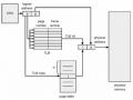 Valid (V) and Invalid (I) Bits in a Page Table
 -
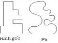 Command to Draw Regular Polygon with N Sides (Polygon) A. Enter Command
3.3.4. Level of reduced sensitivity and resistance to oseltamivir of influenza A/H5N1 virus strains
The number of A/H5N1 influenza virus strains used in the study was 28 viruses isolated from patients infected with A/H5N1 influenza virus during the period 2004-2010. Research results
Table 3.6. IC 50 values of A/H5N1 strains in 2005 and 2008
Year
Strain name | IC 50 value (nM)±SD | IC 50 value threshold | IC 50 Value / IC 50 Value threshold | |
2005 | A/Vietnam/HN30408/05 | 90 ± 5.82 | 2,947 | 30 |
2008 | A/Vietnam/HN31412/08 | 19.04 ± 2.34 | 6 | |
A/Vietnam/HN31413/08 | 14.48 ± 2.09 | 5 | ||
Proof | A/Vietnam/HN30408/05 | 90 | 30 |
The study identified two viruses A/Vietnam/HN31412/08 and A/Vietnam/HN31413/08 circulating in 2008 with IC 50 values of 19.04nM (19.04 ± 2.34nM) and 14.48nM (14.48 ± 2.09nM). These two viruses had IC 50 values 6 times and 5 times higher than the threshold value, respectively. In addition, the strain A/Vietnam/HN30408/05 circulating in 2005 had an IC 50 value determined in 2005 that was 30 times higher than the threshold value (Table 3.6).
3.3.5. Assessment of oseltamivir resistance results of circulating influenza A virus strains
2001 – 2012
According to the WHO classification of the interaction of oseltamivir with influenza viruses related to reduced sensitivity or drug resistance [114], our study results showed that 20 viruses belonging to subtypes A/H1N1; A/H1N1pdm09 and A/H5N1 with IC 50 values higher than the determined threshold value can all be classified into levels of reduced sensitivity or resistance to oseltamivir (Table 3.7).
Table 3.7. Results of classification of reduced sensitivity of influenza A virus to
oseltamivir
Year
Strain name | IC 50 value / IC 50 threshold value | Evaluation of results | |
A/H1N1 virus | |||
2008 | A/Vietnam/TX285/08 | 1294 | Significantly reduced viral sensitivity to the antiviral drug oseltamivir |
A/Vietnam/TB289/08 | 3933 | ||
A/Vietnam/TX200/08 | 1104 | ||
A/Vietnam/TX233/08 | 1097 | ||
A/Vietnam/BT241/08 | 1643 | ||
A/Vietnam/LS324/08 | 145 | ||
2009 | A/Vietnam/32036/09 | 1705 | |
A/Vietnam/EL197/09 | 1407 | ||
A/Vietnam/Q271/09 | 1126 | ||
A/Vietnam/31808/09 | 1278 | ||
A/Vietnam/34381/09 | 1273 | ||
A/Vietnam/N116/09 | 1370 | ||
A/H1N1pdm09 virus | |||
2009 | A/Vietnam/32043/09 | 1422 | Significantly reduced viral sensitivity to the antiviral drug oseltamivir |
A/Vietnam/32060/09 | 1072 | ||
A/Vietnam/32067/09 | 2944 | ||
A/Vietnam/33419/09 | 417 | ||
2011 | A/Vietnam/36530/11 | 356 | |
A/H5N1 virus | |||
2005 | A/Vietnam/HN30408/05 | 30 | Decreased viral sensitivity to the antiviral drug oseltamivir |
2008 | A/Vietnam/HN31412/08 | 6 | There is evidence of reduced sensitivity of the virus to the antiviral drug oseltamivir. |
A/Vietnam/HN31413/08 | 5 | ||
The results of Table 3.7 show that the group of 12 influenza A/H1N1 viruses with IC 50 values 145-3933 times higher than the threshold value will be classified as viruses with significantly reduced sensitivity to the antiviral drug oseltamivir. Similarly, the group of 5 influenza strains H1N1pdm09 is also classified as viruses with significantly reduced sensitivity to the antiviral drug oseltamivir when the IC 50 values of this group of viruses are 356-2944 times higher than the threshold value. The H5N1 virus with an IC 50 value only 5-6 times higher than the threshold value is assessed as having reduced sensitivity (two viruses) and the virus with an IC 50 value 30 times higher than the threshold value is determined to have reduced sensitivity to oseltlamivir. The remaining viruses in the study (322 viruses) all had IC 50 values less than, equal to, or within the threshold value, and in particular, all influenza A/H3N2 virus strains in the study were determined to be sensitive to oseltamivir (Table 3.5).
3.4. Mutation sites on the NA protein of influenza A virus strains associated with oseltamivir resistance
All 20 influenza A viruses that exhibited reduced susceptibility to oseltamivir were subjected to mutational analysis using sequence analysis of the NA gene segment. Common mutation sites associated with reduced susceptibility or resistance to oseltamivir in different virus subtypes are often not the same due to the structure of the NA protein of the subtypes. The expression of reduced susceptibility or resistance to oseltamivir may be the result of one or more mutations in the NA protein of the virus. The viruses analyzed in this study were A/H1N1, A/H1N1pdm09 and A/H5N1 of the NA1 (N1) subtype, so some similar and common mutations in the N1 gene segment recorded as H275Y, N295S or I117V will be analyzed by conventional sequencing methods (Sanger sequencing). Results will be confirmed by comparison with nucleotide sequences of viruses that do not exhibit reduced sensitivity or resistance to oseltamivir and standard reference viruses.
3.4.1. Mutation position on NA protein of A/H1N1 influenza virus strains
related to oseltamivir resistance
Five mutation sites associated with reduced sensitivity or resistance to oseltamivir in the NA gene segment of common A/H1N1 influenza viruses are Q137K (Glutamine to Lysine), Y156H (Tyrosine to Histidine), I223V (Isoleucine to Valine), S247G (Serine to Glycine), and H275Y (Histidine to Tyrosine) [44]. Sequence analysis of the NA gene segment of 12 A/H1N1 influenza viruses showed that all of these viruses had mutations at position 275. Specifically, the nucleotide sequence changed from CAC (the triplet coding for Histidine-H) to TAC (the triplet coding for Tyrosine), and the protein changed at this position was recorded as H275Y (Figure 3.1). No other relevant mutations were detected at positions 137, 156, 223, or 247.
Figure 3.1. Mutation at position 275 on the NA protein of influenza A/H1N1 strains
3.4.2. Mutation positions on the NA protein of influenza A/H1N1pdm09 virus strains
associated with oseltamivir resistance
Influenza A/H1N1pdm09 virus was found to have mutations associated with reduced sensitivity or resistance to oseltamivir including I223M, I223K, S247N, H275Y and co-mutations at two positions Q313K and I427T [44]. Similar to the results of the analysis of the NA gene segment of influenza A/H1N1 virus, a total of 5 A/H1N1pdm09 viruses showing reduced sensitivity to oseltamivir all had the H275Y mutation on the NA protein (Figure 3.2). Other mutations at positions I223M, I223K, S247N were not detected in these viruses.
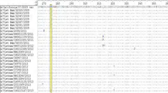
Figure 3.2. Mutation at position 275 on the NA protein of influenza A/H1N1pdm09 strains
3.4.3. Mutation position on NA protein of A/H5N1 influenza virus strains
related to oseltamivir resistance
In the NA gene segment of the avian influenza A/H5N1 virus, the amino acid positions associated with reduced sensitivity or resistance to oseltamivir include I117V, Q136L, D199G, S247N, H275Y, N295S [44]. In this study, all 28 influenza A/H5N1 viruses were analyzed for nucleotide sequences (1413 nucleotides).
The results showed that in the three viruses, the IC 50 increased and the H275Y mutation were detected on virus A/Vietnam/HN30408, but not on the other two viruses, A/Vietnam/HN31412/08 and A/Vietnam/HN31413/08. However, the mutation at position I117V was detected on these two strains. In addition, strain A/Vietnam/HN31209/07 was also found to carry the I117V mutation on the NA coding gene segment, but the IC 50 value was not determined . The remaining mutations Q136L, D199G, S247N, N295S were not identified in this study (Figures 3.3 and 3.4).
Figure 3.3. Mutation at position 117 on the NA protein of influenza A/H5N1 strains
Figure 3.4. Mutation at position 275 on the NA protein of influenza A/H5N1 strains
3.5. Rate of oseltamivir-resistant influenza A virus strains in Northern Vietnam, 2001-2012
Viruses were identified as having reduced sensitivity to oseltamivir based on two determinants, the degree of reduced sensitivity (phenotypic expression) and the presence of resistance-associated point mutations occurring in the NA-encoding gene segment (genotype) of the same virus.
Table 3.8 shows that a total of 20 viruses found to exhibit increased IC 50 at different levels of decreased sensitivity all had associated mutations. The most commonly recorded mutation was H275Y (Histidine to Tyrosine), occurring in 18/20 viruses, while the I117V mutation only occurred in 2 viruses with IC 50 values 5-6 times greater than the threshold.