OnSelectionChanged | The name of the function that is executed when the user selects an option. day, week or month |
OnVisibleMonthChanged | The name of the function that is executed when the user moves to it. another month |
Maybe you are interested!
-

 Accounting Entry Procedure According to Journal Accounting Form – Book
 -
 Spss Data Processing Results of Survey Form for Former Students
 -
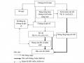 Accounting Sequence Diagram in Journal - Ledger Form.
 -
 Sequence Diagram of Recording Revenue, Expenses and Determining Business Results in the General Journal Accounting Form
 -
 Car body electrical practice - 8
zt2i3t4l5ee
zt2a3gs
zt2a3ge
zc2o3n4t5e6n7ts
If the voltage is out of specification, replace the wire or connector.
If the voltage is within specification, install the front fog light relay and follow step 5.
Step 5 Check the front fog light switch
- Remove the D4 connector of the fog light switch
- Use a multimeter to measure the resistance of the front fog light switch.
Measurement location
Condition
Standard
D4-3 (BFG) -D4-4 (LFG)
Light switchFront Fog OFF
>10kΩ
D4-3 (BFG) -D4-4 (LFG)
Front fog light switchON
<1 Ω
- Standard resistor
D4 connector is located on the combination switch assembly.
If the resistance is out of specification, replace the combination switch (the fog light switch is located in the combination switch).
If the resistance is within specification, follow step 6.
Step 6 Check wiring and connectors (front fog light relay-light selector switch)
- Disconnect connector D4 of the combination switch assembly
- Use a voltmeter to measure the voltage value of jack D4 on the wire side.
Measurement location
Control modecontrol
Standard
D4-3 (BFG) - (-) AQ
TAIL
11 to 14 V
D4 connector for the wiring of the combination switch assembly
If the voltage does not meet the standard, replace the wire or connector.
If the voltage is within standard, there may have been an error in the previous measurements.
Step 7 Check the front fog lights
- Remove the front fog light electrical connector.
- Supply battery voltage to the fog lamp terminals
Jack 8, B9 of front fog lamp on the electrical side
blind first.
Power supply location
Terms and Conditions
Battery positive terminal - Terminal 2Battery negative terminal - Terminal 1
Fog lightsbefore morning
- If the light does not come on, replace the bulb.
If the light is on, re-plug the jack and continue to step 8.
Step 8 Check wiring and connectors (relay and front fog lights)
- Disconnect the B8 and B9 connectors of the front fog lights.
- Use a voltmeter to measure voltage at the following locations:
Measurement location
Switch location
Terms and Conditions
B8-2 - (-) AQ
Electric lock ON TAIL size switchFog switch ON
11 to 14 V
B9-2 - (-) AQ
Electric lock ONTAIL size switch Fog switch ON
11 to 14 V
B8 and B9 connectors on the front fog lamp wiring side
Voltage is not up to standard, repair or replace the jack. If up to standard, there may have been an error in the measurement process.
2.2.4. Procedure for removing, installing and adjusting fog lights 1. Procedure for removing
- Remove the front inner ear pads
Use a screwdriver to remove the 3 screws and remove the front part of the front inner ear liner
-Remove the fog light assembly
+ Disconnect the connector.
+ Use a screwdriver to remove 3 screws to remove the fog light cover
2. Installation sequence
-Rotate the fog lamp bulb in the direction indicated by the arrow as shown in the figure and remove the fog lamp from the fog lamp assembly.
-Rotate the fog light bulb in the direction indicated by the arrow as shown in the figure and install the light into the fog light assembly.
- Use a screwdriver to install the fog light cover
-Install the electrical connector
Attention: Be careful not to damage the plastic thread on the lamp assembly.
- Install the front inner ear pads
Use a screwdriver to install the front inner bumper with 3 screws.
3. Prepare the vehicle to adjust the fog light convergence. Prepare the vehicle:
- Make sure there is no damage or deformation to the vehicle body around the fog lights.
- Add fuel to the fuel tank
- Add oil to standard level.
- Add engine coolant to standard level.
- Inflate the tire to standard pressure.
- Place spare tire, tools and jack in original design position
- Do not leave any load in the luggage compartment.
- Let a person weighing about 75 kg sit in the driver's seat.
4. Prepare to check the fog light convergence
a/ Prepare the vehicle status as follows:
- Place the car in a dark enough place to see the lines. The lines are the dividing line, below which the light from the fog lights can be seen but above which it cannot.
- Place the car perpendicular to the wall.
- Keep a distance of 7.62 m between the center of the fog lamp and the wall.
- Park the car on level ground.
- Press the car down a few times to stabilize the suspension.
Note: A distance of approximately 7.62 m is required between the vehicle (fog lamp center) and the wall to adjust the convergence correctly. If the distance of 7.62 m cannot be achieved, set the correct distance of 3 m to check and adjust the fog lamp convergence. (Since the target area varies with the distance, please follow the instructions as shown in the figure.)
b/ Prepare a piece of thick white paper about 2 m high and 4 m wide to use as a screen.
c/ Draw a vertical line through the center of the screen (line V).
d/ Set the screen as shown in the picture. Note:
- Keep the screen perpendicular to the ground.
- Align the V line on the screen with the center of the vehicle.
e/Draw the reference lines (H, V LH and V RH lines) on the screen as shown in the figure.HINT:
Mark the center of the fog lamp on the screen. If the center mark cannot be seen on the fog lamp, use the center of the fog lamp or the manufacturer's name mark on the fog lamp as the center mark.
H line (fog light height):
Draw a line across the screen so that it passes through the center mark. Line H should be at the same height as the center mark of the fog light bulb.
Line V LH, V RH (center mark position of left fog lamp LH and right fog lamp RH):
Draw two lines so that they intersect line H at the center marks.
5. Check the fog light convergence
a/ Cover the fog lamp or remove the connector of the other side fog lamp to prevent light from the unchecked fog lamp from affecting the fog lamp convergence test.
b/ Start the engine.
c/ Turn on the fog lights and make sure that the dividing line is outside the standard area as shown in the drawing.
6. Adjust the fog light convergence
Use a screwdriver to adjust the fog light to the standard area by turning the toe adjustment screw.
Note: If the screw is adjusted too far, loosen it and then tighten it again, so that the last rotation of the light adjustment screw is clockwise.
3. Self-study questions
1. Describe the operating principle of the lighting system with automatic headlight function
2. Describe the operating principle of the lighting system with the function of rotating headlights when turning
3. Draw diagram and connect lighting system on Hyundai Porter car
4. Draw diagram and connect lighting system on Honda Accord 1992
5. Draw the lighting circuit on a 1993 Toyota Lexus
LESSON 3 MAINTENANCE AND REPAIR OF SIGNAL SYSTEM
I. IMPLEMENTATION GOAL
After completing this lesson, students will be able to:
- Distinguish between types of signals on cars
- Correctly describe common symptoms and suspected areas causing damage.
- Connecting signal circuits ensures technical requirements
- Disassemble, install, check, maintain and repair the signal system to ensure technical requirements.
- Ensure safety in work and industrial hygiene
II. LESSON CONTENT
1. General description
The signal system equipped on cars aims to create signals to notify other vehicles participating in traffic about the vehicle's operating status such as: stopping, parking, braking, reversing, turning...
Signals are used either by light such as headlamps, brake lights, turn signals….. or by sound such as horns, reverse music….
Just like the lighting system. A signal system circuit usually consists of: battery, fuse, wire, relay, electrical load and control switch. Only some switches of the signal system are on the combination switch. The switches of other signals are usually located in different locations such as in the gearbox or brake pedal……
2. Maintenance and repair
2.1. Turn signals and hazard lights
The installation location of the turn signal is shown in Figure 3.1. The turn signal control switch is located in the combination switch under the steering wheel. Turning this switch to the right or left will make the turn signal turn right or left.
The hazard light switch is used when the vehicle has a problem while participating in traffic. When the hazard light switch is turned on, all the turn signals on the vehicle will light up at a certain frequency. The hazard light switch is usually placed separately from the turn signal switch (some old cars integrate the hazard and turn signal switches on the same combination switch cluster).
Figure 3.1 Turn signal switch Figure 3.2 Hazard switch
The part that generates the flashing frequency for the lights is called a turn signal relay. The turn signal relay usually has 3 terminals: B (positive power supply); E (negative power supply); L (providing the turn signal switch to distribute to the
lamp)
2.1.1. Circuit diagram
To generate the frequency for the turn signal, a turn signal relay is used in the turn signal circuit. The current from the turn signal relay will be sent to the turn signal switch assembly to distribute the current to the turn signal lights for the driver's purpose.
Figure 3.3. Schematic diagram of a turn signal circuit without a hazard switch
1. Battery; 2. Electric lock; 3. Turn signal relay; 4. Turn signal switch; 5. Turn signal lamp; 6. Turn signal lamp; 7. Hazard switch
Figure 3.4 Schematic diagram of turn signal circuit with hazard switch
1. Battery; 2. Combination switch cluster; 3. Turn signal;
4. Turn signal light; 5. Turn signal relay
Today's cars no longer use three-pin turn signal relays (B, L, E) but use eight-pin turn signal relays (figure 3.5) (pin number 8 is used for hazard lights).
For this type, the current supplying the turn signal lights is supplied directly from the turn signal relay to the lights.
div.maincontent .p { color: black; font-family:"Times New Roman", serif; font-style: normal; font-weight: normal; text-decoration: none; font-size: 14pt; margin:0pt; } div.maincontent p { color: black; font-family:"Times New Roman", serif; font-style: normal; font-weight: normal; text-decoration: none; font-size: 14pt; margin:0pt; } div.maincontent .s1 { color: black; font-family:"Times New Roman", serif; font-style: normal; font-weight: normal; text-decoration: none; font-size: 13pt; } div.maincontent .s2 { color: black; font-family:"Times New Roman", serif; font-style: italic; font-weight: normal; text-decoration: none; font-size: 14pt; } div.maincontent .s3 { color: black; font-family:"Times New Roman", serif; font-style: normal; font-weight: normal; text-decoration: none; font-size: 14pt; } div.maincontent .s4 { color: black; font-family:"Times New Roman", serif; font-style: normal; font-weight: normal; text-decoration: none; font-size: 13pt; } div.maincontent .s5 { color: black; font-family:"Times New Roman", serif; font-style: normal; font-weight: normal; text-decoration: none; font-size: 13pt; vertical-align: 1pt; } div.maincontent .s6 { color: black; font-family:"Times New Roman", serif; font-style: normal; font-weight: normal; text-decoration: none; font-size: 11pt; } div.maincontent .s7 { color: black; font-family:"Times New Roman", serif; font-style: normal; font-weight: normal; text-decoration: none; font-size: 14pt; vertical-align: -9pt; } div.maincontent .s8 { color: black; font-family:"Times New Roman", serif; font-style: normal; font-weight: normal; text-decoration: none; font-size: 11pt; } div.maincontent .s9 { color: #008000; font-family:"Times New Roman", serif; font-style: normal; font-weight: normal; text-decoration: none; font-size: 14pt; } div.maincontent .s10 { color: black; font-family:"Times New Roman", serif; font-style: italic; font-weight: normal; te
Car body electrical practice - 8
zt2i3t4l5ee
zt2a3gs
zt2a3ge
zc2o3n4t5e6n7ts
If the voltage is out of specification, replace the wire or connector.
If the voltage is within specification, install the front fog light relay and follow step 5.
Step 5 Check the front fog light switch
- Remove the D4 connector of the fog light switch
- Use a multimeter to measure the resistance of the front fog light switch.
Measurement location
Condition
Standard
D4-3 (BFG) -D4-4 (LFG)
Light switchFront Fog OFF
>10kΩ
D4-3 (BFG) -D4-4 (LFG)
Front fog light switchON
<1 Ω
- Standard resistor
D4 connector is located on the combination switch assembly.
If the resistance is out of specification, replace the combination switch (the fog light switch is located in the combination switch).
If the resistance is within specification, follow step 6.
Step 6 Check wiring and connectors (front fog light relay-light selector switch)
- Disconnect connector D4 of the combination switch assembly
- Use a voltmeter to measure the voltage value of jack D4 on the wire side.
Measurement location
Control modecontrol
Standard
D4-3 (BFG) - (-) AQ
TAIL
11 to 14 V
D4 connector for the wiring of the combination switch assembly
If the voltage does not meet the standard, replace the wire or connector.
If the voltage is within standard, there may have been an error in the previous measurements.
Step 7 Check the front fog lights
- Remove the front fog light electrical connector.
- Supply battery voltage to the fog lamp terminals
Jack 8, B9 of front fog lamp on the electrical side
blind first.
Power supply location
Terms and Conditions
Battery positive terminal - Terminal 2Battery negative terminal - Terminal 1
Fog lightsbefore morning
- If the light does not come on, replace the bulb.
If the light is on, re-plug the jack and continue to step 8.
Step 8 Check wiring and connectors (relay and front fog lights)
- Disconnect the B8 and B9 connectors of the front fog lights.
- Use a voltmeter to measure voltage at the following locations:
Measurement location
Switch location
Terms and Conditions
B8-2 - (-) AQ
Electric lock ON TAIL size switchFog switch ON
11 to 14 V
B9-2 - (-) AQ
Electric lock ONTAIL size switch Fog switch ON
11 to 14 V
B8 and B9 connectors on the front fog lamp wiring side
Voltage is not up to standard, repair or replace the jack. If up to standard, there may have been an error in the measurement process.
2.2.4. Procedure for removing, installing and adjusting fog lights 1. Procedure for removing
- Remove the front inner ear pads
Use a screwdriver to remove the 3 screws and remove the front part of the front inner ear liner
-Remove the fog light assembly
+ Disconnect the connector.
+ Use a screwdriver to remove 3 screws to remove the fog light cover
2. Installation sequence
-Rotate the fog lamp bulb in the direction indicated by the arrow as shown in the figure and remove the fog lamp from the fog lamp assembly.
-Rotate the fog light bulb in the direction indicated by the arrow as shown in the figure and install the light into the fog light assembly.
- Use a screwdriver to install the fog light cover
-Install the electrical connector
Attention: Be careful not to damage the plastic thread on the lamp assembly.
- Install the front inner ear pads
Use a screwdriver to install the front inner bumper with 3 screws.
3. Prepare the vehicle to adjust the fog light convergence. Prepare the vehicle:
- Make sure there is no damage or deformation to the vehicle body around the fog lights.
- Add fuel to the fuel tank
- Add oil to standard level.
- Add engine coolant to standard level.
- Inflate the tire to standard pressure.
- Place spare tire, tools and jack in original design position
- Do not leave any load in the luggage compartment.
- Let a person weighing about 75 kg sit in the driver's seat.
4. Prepare to check the fog light convergence
a/ Prepare the vehicle status as follows:
- Place the car in a dark enough place to see the lines. The lines are the dividing line, below which the light from the fog lights can be seen but above which it cannot.
- Place the car perpendicular to the wall.
- Keep a distance of 7.62 m between the center of the fog lamp and the wall.
- Park the car on level ground.
- Press the car down a few times to stabilize the suspension.
Note: A distance of approximately 7.62 m is required between the vehicle (fog lamp center) and the wall to adjust the convergence correctly. If the distance of 7.62 m cannot be achieved, set the correct distance of 3 m to check and adjust the fog lamp convergence. (Since the target area varies with the distance, please follow the instructions as shown in the figure.)
b/ Prepare a piece of thick white paper about 2 m high and 4 m wide to use as a screen.
c/ Draw a vertical line through the center of the screen (line V).
d/ Set the screen as shown in the picture. Note:
- Keep the screen perpendicular to the ground.
- Align the V line on the screen with the center of the vehicle.
e/Draw the reference lines (H, V LH and V RH lines) on the screen as shown in the figure.HINT:
Mark the center of the fog lamp on the screen. If the center mark cannot be seen on the fog lamp, use the center of the fog lamp or the manufacturer's name mark on the fog lamp as the center mark.
H line (fog light height):
Draw a line across the screen so that it passes through the center mark. Line H should be at the same height as the center mark of the fog light bulb.
Line V LH, V RH (center mark position of left fog lamp LH and right fog lamp RH):
Draw two lines so that they intersect line H at the center marks.
5. Check the fog light convergence
a/ Cover the fog lamp or remove the connector of the other side fog lamp to prevent light from the unchecked fog lamp from affecting the fog lamp convergence test.
b/ Start the engine.
c/ Turn on the fog lights and make sure that the dividing line is outside the standard area as shown in the drawing.
6. Adjust the fog light convergence
Use a screwdriver to adjust the fog light to the standard area by turning the toe adjustment screw.
Note: If the screw is adjusted too far, loosen it and then tighten it again, so that the last rotation of the light adjustment screw is clockwise.
3. Self-study questions
1. Describe the operating principle of the lighting system with automatic headlight function
2. Describe the operating principle of the lighting system with the function of rotating headlights when turning
3. Draw diagram and connect lighting system on Hyundai Porter car
4. Draw diagram and connect lighting system on Honda Accord 1992
5. Draw the lighting circuit on a 1993 Toyota Lexus
LESSON 3 MAINTENANCE AND REPAIR OF SIGNAL SYSTEM
I. IMPLEMENTATION GOAL
After completing this lesson, students will be able to:
- Distinguish between types of signals on cars
- Correctly describe common symptoms and suspected areas causing damage.
- Connecting signal circuits ensures technical requirements
- Disassemble, install, check, maintain and repair the signal system to ensure technical requirements.
- Ensure safety in work and industrial hygiene
II. LESSON CONTENT
1. General description
The signal system equipped on cars aims to create signals to notify other vehicles participating in traffic about the vehicle's operating status such as: stopping, parking, braking, reversing, turning...
Signals are used either by light such as headlamps, brake lights, turn signals….. or by sound such as horns, reverse music….
Just like the lighting system. A signal system circuit usually consists of: battery, fuse, wire, relay, electrical load and control switch. Only some switches of the signal system are on the combination switch. The switches of other signals are usually located in different locations such as in the gearbox or brake pedal……
2. Maintenance and repair
2.1. Turn signals and hazard lights
The installation location of the turn signal is shown in Figure 3.1. The turn signal control switch is located in the combination switch under the steering wheel. Turning this switch to the right or left will make the turn signal turn right or left.
The hazard light switch is used when the vehicle has a problem while participating in traffic. When the hazard light switch is turned on, all the turn signals on the vehicle will light up at a certain frequency. The hazard light switch is usually placed separately from the turn signal switch (some old cars integrate the hazard and turn signal switches on the same combination switch cluster).
Figure 3.1 Turn signal switch Figure 3.2 Hazard switch
The part that generates the flashing frequency for the lights is called a turn signal relay. The turn signal relay usually has 3 terminals: B (positive power supply); E (negative power supply); L (providing the turn signal switch to distribute to the
lamp)
2.1.1. Circuit diagram
To generate the frequency for the turn signal, a turn signal relay is used in the turn signal circuit. The current from the turn signal relay will be sent to the turn signal switch assembly to distribute the current to the turn signal lights for the driver's purpose.
Figure 3.3. Schematic diagram of a turn signal circuit without a hazard switch
1. Battery; 2. Electric lock; 3. Turn signal relay; 4. Turn signal switch; 5. Turn signal lamp; 6. Turn signal lamp; 7. Hazard switch
Figure 3.4 Schematic diagram of turn signal circuit with hazard switch
1. Battery; 2. Combination switch cluster; 3. Turn signal;
4. Turn signal light; 5. Turn signal relay
Today's cars no longer use three-pin turn signal relays (B, L, E) but use eight-pin turn signal relays (figure 3.5) (pin number 8 is used for hazard lights).
For this type, the current supplying the turn signal lights is supplied directly from the turn signal relay to the lights.
div.maincontent .p { color: black; font-family:"Times New Roman", serif; font-style: normal; font-weight: normal; text-decoration: none; font-size: 14pt; margin:0pt; } div.maincontent p { color: black; font-family:"Times New Roman", serif; font-style: normal; font-weight: normal; text-decoration: none; font-size: 14pt; margin:0pt; } div.maincontent .s1 { color: black; font-family:"Times New Roman", serif; font-style: normal; font-weight: normal; text-decoration: none; font-size: 13pt; } div.maincontent .s2 { color: black; font-family:"Times New Roman", serif; font-style: italic; font-weight: normal; text-decoration: none; font-size: 14pt; } div.maincontent .s3 { color: black; font-family:"Times New Roman", serif; font-style: normal; font-weight: normal; text-decoration: none; font-size: 14pt; } div.maincontent .s4 { color: black; font-family:"Times New Roman", serif; font-style: normal; font-weight: normal; text-decoration: none; font-size: 13pt; } div.maincontent .s5 { color: black; font-family:"Times New Roman", serif; font-style: normal; font-weight: normal; text-decoration: none; font-size: 13pt; vertical-align: 1pt; } div.maincontent .s6 { color: black; font-family:"Times New Roman", serif; font-style: normal; font-weight: normal; text-decoration: none; font-size: 11pt; } div.maincontent .s7 { color: black; font-family:"Times New Roman", serif; font-style: normal; font-weight: normal; text-decoration: none; font-size: 14pt; vertical-align: -9pt; } div.maincontent .s8 { color: black; font-family:"Times New Roman", serif; font-style: normal; font-weight: normal; text-decoration: none; font-size: 11pt; } div.maincontent .s9 { color: #008000; font-family:"Times New Roman", serif; font-style: normal; font-weight: normal; text-decoration: none; font-size: 14pt; } div.maincontent .s10 { color: black; font-family:"Times New Roman", serif; font-style: italic; font-weight: normal; te
For example: The aspx page is as follows:
<body>
<Form id="Form1" runat="Server">
<asp:Calendar ID="Calendar1" DayNameFormat="Full" runat="Server">
<WeekendDayStyle BackColor="#fafad2" ForeColor="#ff0000" />
<DayHeaderStyle ForeColor="#0000ff" />
<TodayDayStyle BackColor="#00ff00" />
</asp:Calendar>
</Form>
</body>
The .aspx page above displays a calendar, the days of the week are written in full blue, weekends are written in red on a yellow background, the current date is shown with a green background as shown below:
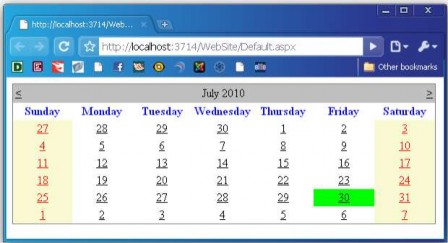
Figure 3.37. Illustration of using the Calendar control
For example: The aspx page is as follows:
<body>
<Form id="Form1" runat="Server">
<asp:Calendar DayNameFormat="Full" runat="Server" SelectionMode="DayWeekMonth" SelectMonthText="<*>"
SelectWeekText="<->"/>
<SelectorStyle BackColor="#f5f5f5" />
</asp:Calendar>
</Form>
</body>
The aspx page above displays a calendar with the days of the week listed in full, the user can select a day, a week and a month, the selected day/week/month is displayed with a gray background color as shown below:
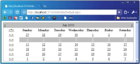
Figure 3.38. Illustration of using the Calendar control
- CalendarDay Control
The CalendarDay Control represents a day in a calendar Control.
Attributes:
Properties
Describe | |
Date | Day of the Day variable |
DayNumberText | Day number (day) of the day |
IsOtherMonth | Specifies whether days in other months are displayed. Are not |
IsSelectable | Determine if the date is selectable |
IsSelected | Determine whether a date is selected or not |
IsToday | Determines whether it is the current date or not |
IsToday | Determine whether it is Saturday or Sunday. |
- File Upload Control
The FileUpload control allows users to upload files from their own Web application. The uploaded files can be stored somewhere, either on the hard drive or in the database.
Attributes:
Properties
Describe | |
Enable | Allows disabling of FileUpload control. |
FileBytes | Allows to get the uploaded file contents as a Byte array. |
FileContent | Allows to get the contents of the uploaded file line by line data |
FileName | Get the uploaded file name |
HasFile | Returns true when File is Uploaded |
PostedFile | Enables you to get the uploaded file wrapped in the HttpPostedFile object. |
The PostedFile property of the FileUpload control allows to get information from the uploaded File wrapped in an HttpPostedFile object. This object will give more information about the Upload file.
The HttpPostedFile class has the following properties:
Properties
Describe | |
ContentLength | Get the size of the Upload File in bytes |
ContentType | ContentType: get the MIME type of the Upload File |
FileName | Allows to get the name of the uploaded file. |
InputStream | Allow upload as an input stream. |
Example: Upload an image file to the Server's hard drive. Fileupload.aspx page
<body>
<Form id="Form1" runat="Server">
<div>
<asp:Label ID="Label1" runat="Server" Text="Select File"></asp:Label>
<asp:FileUpload ID="FileUpload1" runat="Server" Width="286px" /><br />
<asp:Button ID="Button1" runat="Server" Text="Add image" Width="92px" onclick="Button1_Click" /><hr />
<asp:DataList ID="listImage" RepeatColumns="3" runat="Server">
<ItemTemplate>
<asp:Image ID="Image1" ImageUrl='<%# Eval("Name", "~/Upload/{0}") %>' Runat="Server" /><br />
<%# Eval("Name") %>
</ItemTemplate>
</asp:DataList>
</div>
</Form>
</body>
Fileupload.aspx.cs page code
using System; using System.Data; using System.IO;
public partial class _Default : System.Web.UI.Page
{
protected void Page_Load(object sender, EventArgs e)
{
}
protected void Page_PreRender(){
string upload_folder = MapPath("~/Upload/"); DirectoryInfo dir = new DirectoryInfo(upload_folder); listImage.DataSource = dir.GetFiles(); listImage.DataBind();
}
bool CheckFileType(string fileName)
{
string ext = Path.GetExtension(fileName); switch (ext.ToLower())
{
case ".gif": return true; case ".png": return true; case ".jpg": return true; case ".jpeg": return true; default: return false;
}
}
protected void Button1_Click(object sender, EventArgs e){ if (FileUpload1.HasFile){
if(CheckFileType(FileUpload1.FileName)){
string filepath ="~/Upload/" + FileUpload1.FileName; FileUpload1.SaveAs(MapPath(filepath));
}
}
}
}
In the Button1_Click event, check if there is a File to Upload? If yes, check if the uploaded file is in the correct image format using the CheckFileType function. If yes, write the file to the Server using the SaveAs method of the FileUpload control.
- ViewState object
The ViewState object is provided to save the information of the Web page after the Web Server sends the results back to the Client. By default, when created, Web pages will allow the use of the ViewState object through the EnableViewState property (of the Web page) = True.
Assign a value to ViewState.
ViewState("State name") = <value>
Gets values from ViewState object.
<variable> = ViewState("State name")
- ASP.NET page events
When working with ASP.NET pages, we can encounter some page events in the following order: PreInit, Init, InitComplete, PreLoad, Load, LoadComplete, PreRender, PreRenderComplete, UnLoad. To declare ASP.NET page events, go to the View|Component Design menu or R-Click|View Component Design in the Solution Explorer window. Then, click the event icon in the  Properties window, a list of page events will be displayed.
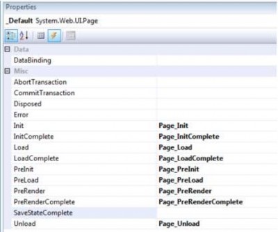
Figure 3.39. ASP.NET page events
Init: The Page_Init event occurs first when the Web page is requested.
Load: This event is where most of the processing and initialization of the web page will be done. This event always occurs every time the web page is requested.
PreRender: This event occurs when the Web page is about to be returned to the Client.
Unload: This event is the opposite of the Page_Init event. If the Page_Init event occurs first when the Web page is requested, then here, Page_Unload is the last event, occurring after all other events.
- PageLoad event and IsPostback property
The presentation will be based on the division into the first Request and the Request from the second time onwards. In the case of the first Request, if ASP.NET receives an HTTP Request from the Web Browser, it will create a Form instance. The Form instance will create a tree of Control instances inside it. Then, start the Load event and call the event handler to create it. In the event handler, set the property of the Control in the Control tree to control the display of the screen. Finally, the Form will generate HTML and return it to the Web Browser. The generated HTML is processed to the Control, and the Control will generate HTML that matches its own property. Furthermore, it is possible to save the state of the Control into the ViewState when needed and the tag
<input type=“hidden”> will be generated.
Request case from 2nd time onwards
The content until the part of receiving HTTP Request, creating the tree of Form instance and Control instance is the same as the first Request. In Postback Request includes ViewState created in the previous Response, so it will set Control property the same as when returning the previous Response based on that ViewState.
Then, comparing the state between the HTTP Request and the current Control state (restored by ViewState) we will start the appropriate event. Since the Form is loaded similar to the first Request case, first, load event if the value entered into the textbox is different from ViewState and if TextChanged event, button is clicked, then we feel like Clicked event.
Of course, with load event handlers where both the first Request and the Postback (Page_Load() method) are called unconditionally, use the IsPostback property to indicate whether there is a Postback or not, to replace the processing content. Normally, the Page_Load() method will be as follows:
protected void Page_Load(object sender, EventArgs e)
{ // Use IsPostback property to determine if there is a Postback or not? if (!Page.IsPostback) {
// here will describe the initialization process.
}
// Here will describe the common handling in all events.
}
The following Requests are similar to the first Request. The Control will generate HTML and ViewState will be generated to hold the state.
- AutoPostback property of some Web Server Controls
When changing some values: background color, foreground color, font name, font size, border style, default picture or greeting text, if the AutoPostback property of the corresponding Web Server Controls: <asp:TextBox>, <asp:dropdownlist>,
<asp:radiobuttonlist>, <asp:checkbox> on the page set value = true, we will see the card editing will be updated immediately after the change.
A Web Server Control has the AutoPostback=true attribute, which means that the Control will Postback to the Server every time the user interacts with that Control (this attribute supports some ASP.NET Controls such as CheckBox, TextBox, ListControl because by default they do not automatically Postback to the Server. With other ASP.NET Controls such as Button, they will automatically Postback to the Server every time the user interacts with them). Therefore, it is necessary to set this attribute = true for the chkAll checkbox as the code below, so that the Server can receive the signal from this Control after the user interacts.
<asp:CheckBox ID="chkAll" runat="Server" OnCheckedChanged="chkAll_CheckedChanged" AutoPostback="true" />
3.1.7. Validation Controls
When building an application, it is necessary to check the data entered by the user to limit the errors in the data entered to ensure that the data processing is performed accurately according to the business requirements. If writing code to check, it will take a lot of time (using JavaScript or VBScript). Web Form supports Validation Controls to check the data entered by the user in the Controls server, the purpose is to avoid users entering wrong information or not leaving important required information blank, ...
With the previous version of ASP.NET, ASP, to fix that error, we had to write JavaScript code to catch that error, but with ASP.NET, we have provided controls to check the validity of input controls on the Form. In this section, we will learn about those controls and then learn how to extend those controls as desired to check input on the Client side.
There are 6 Validation controls in .Net framework:
+ RequiredFieldValidator: Requires the user to enter a value into the specified field on the Form
+ RangeValidator: Checks whether the input value is within a predetermined minimum and maximum range.
+ CompareValidator: Compares whether the entered value is equal to a value of another field on the Form.
+ RegularExpressionValidator: Compares the input value with a regular expression, which can be an email, phone number, bank account number, etc.
+ CustomValidator: can customize the Validator object as you like
+ ValidationSummary: allows displaying a summary of all errors on 1 page.
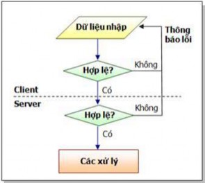
Figure 3.40. Diagram of checking data entered on Form at Client and Server
When Postbacking to the Server, the Web page always checks the validity of the data (if required in the design). If the data is invalid (blank, value domain violation, incorrect password re-entered, ...), the Web page will not be able to Postback to the Server.
Common properties of validation Controls.
Properties
Describe | |
ControlToValidate | The name of the control to check. This is the property that must be verified. defined when using Validation Control. |
Text | The message string that appears when an error occurs. |
ErrorMessage | The message string appears in the Validation Summary control. This value will be displayed in place of the control. control if no value is assigned to the Text property. |
Display | Display format rules: - None: Do not display error message (still check data) - Static: In the absence of data violations, the control is not visible but still occupies the position as it was designed. - Dynamic: In the absence of a data breach, |