Heat treatment ensures its correct technical requirements such as taper and ovality of the shaft.
< 0.01 mm, hardness 45 50 HRC. If the shaft keyway is worn, it must be re-welded and then milled a new keyway, at an angle of 90 0 180 0 from the old keyway .
In addition, worn bearings, broken pump blades, pitted, cracked pump housings, damaged sealing parts, can be repaired and replaced with new parts.
1.5.2 Radiator damage and repair
During long-term use, the cooling system has the following damages: the core is dirty, the pipes are scaled and leaking due to hard water.
Maybe you are interested!
-

 Research on treatment of rotator cuff tears using modified Mason-Allen tendon endoscopic suturing technique and creating micro-damage at the attachment area - 2
 -
 Phenomenon that changes reaction rate - 2
 -
 Civil Remedies Applied to Deal with Infringement of Industrial Property Rights
 -
 Maintenance and repair of internal combustion engines Rural Electromechanical Profession - Lao Cai Community College - 21
 -
 Esp Control Brake System Against Under- or Over-Revving Phenomenon
In addition, the radiator is dented and punctured.
Check the water tank for airtightness by immersing it in a water tank and then applying compressed air to the tank with a residual pressure of 0.03 0.05 MPa (0.3 0.5 kg/cm 2 ). When doing this, the holes in the water tank must be sealed with rubber plugs; one of the plugs has a flexible tube to receive air from an air compressor. If air bubbles appear, it means that the water tank is damaged. Repair a leaking water tank by soldering copper or tin.
Check for dents by observing. If the amount of damaged pipes does not exceed 5%, the water tank can still be used. If it exceeds 5%, replace it. When replacing the pipes, release the weld between the water tank of the water tank and the tube bundle. Then, heat the tubular steel bars, release the weld of the damaged pipes and use flat pliers to pull the pipes out of the tube bundle. Place the new pipe or the re-welded pipe with a bar inside. Pull out the bar and widen the ends of the newly placed pipes. Finally, weld the pipe ends to the tube bundle support plate and to the upper and lower water tanks.
1.5.3 Fan damage and repair
Fan blades often have damage such as: deformation, warping causing imbalance leading to noisy engine operation. In addition, there may be damage to the joints between the blades and the body and wear on the pulley shaft (depending on the structure or not).
The fan is removed and placed on a table to check the angle of the fan blade relative to the plane perpendicular to the axis. If warped, straighten it by cold method.
If the rivet is loose (check by shaking your hand), remove the rivet and re-rivet it with a larger diameter rivet.
Worn shaft bearing should be repaired with bearing suitable to shaft size.
Then balance the whole assembly on the static balance stand and perform a test rotation. The place where it stops is the place where it is unbalanced. We drill out the pulley or install bolts on the opposite part.
1.6 Cooling system maintenance techniques
To ensure the cooling system works normally, the following tasks need to be performed:
Water poured into the cooling system must be clean water, preferably soft water. Soft water has good washing ability, so use the water discharged from the cooling system because it has less lime salt. Hard water can be softened by boiling for 30 minutes, adding caustic soda (NaOH) or sodium phosphate. Depending on the hardness of the water, dissolve 6 to 10 grams of NaOH or 10 to 20 grams of sodium phosphate in 10 liters of hot water.
Pour water into the water tank up to the upper neck level. During operation, the water level should not be lower than 8 cm from the upper surface of the water tank filling neck.
When pouring water into the cooling system of an overheated engine, open the radiator cap carefully because the pressure in the system is lower than atmospheric pressure, the water boils instantly and can splash out. First let the engine cool down for a while, then stop in the wind direction, use gloves to open the radiator cap. Pour slowly and make sure the engine is running. In winter, do not pour too hot water into a cold engine; sudden changes in temperature can lead to cracks in the cylinder head and engine cover.
Do not operate the engine when the water temperature in the radiator is over 100 0 C.
When performing technical maintenance on the tractor, the crew driver checks the water level in the radiator, checks the tightness of the joints, and fixes any water leaks. A lot of water flowing from the drain hole in the water pump housing shows that the parts
If the pump's sealing mechanism is worn and needs to be replaced, check the condition of the steam valve if water loss is not due to leakage.
Periodically flush the cooling system with clean water to remove rust and dirt from the system. Wash the outside of the radiator core and blow with compressed air.
After 60 hours of operation, the water pump bearing needs to be lubricated; to do this, clean the grease nipple and pump it 3 to 4 times with a hand pump. Check the tension of the transmission belt (between the two pulleys). When the transmission belt tension is normal, if a force of 80 N (8 kg) is applied to the edge of the fan blade, the fan blade will rotate. The tension of the transmission belt can be checked by pressing down on the belt with your finger. If a force of 50 N (5 kg) is applied, the transmission belt will sag 10 to 15 mm. The tension of the transmission belt is adjusted by moving the generator.
After 960 hours of operation, the cooling system must be flushed if it is necessary to remove residue from the system. To flush the system, use a solution of 150 grams of sodium phosphate trihydrate, 20 grams of caustic potash, 25 grams of caustic soda with 10 liters of water. Heat the engine to 80 0 85 0 C, then drain the solution and rinse the system with clean water.
Clean the dirt from the cooling system immediately after flushing: use a mixture (1 kg NaOH + 0.5 liter kerosene + 10 liters H 2 O) or caustic soda (750 800 grams caustic soda + 0.25 liters kerosene + 10 liters water). Pour the solution into the system, let the tractor work for a shift. Then drain the solution, pour clean water into the system and let the engine work for about 3 5 minutes, then drain the water. Use the water to flush the cooling system several times.
If there are no aluminum alloy parts in the cooling system, after cleaning the dirt with caustic soda solution, clean it with 4% hydrochloric acid (HCl) solution mixed with alkaline retardant. Heat the solution to 40 0 50 0 C , pour it into the system and let the engine run for about 15 20 minutes, then drain it. Then rinse the system carefully with clean water.
During seasonal technical maintenance, it is necessary to check the operation of the thermostat valve and the thermometer reading. Remove the thermostat valve from the body, observe and check to make sure there is no damage. Place the valve in a basin of cold water, boil
Heat the water and observe at what temperature the center valve opens. It should start to open at 70 0 C and be fully open at 85 0 C. The total valve travel is approximately 9 mm.
Check the thermometer by comparing its reading with that of a sample thermometer immersed in the radiator neck.
Lesson 5: MAINTENANCE AND REPAIR OF LUBRICATION SYSTEM
Objective of the lesson:
After completing this lesson, students will be able to:
- Present the tasks and classify lubrication systems.
- Present the structural diagram and general operating principle of the lubrication system.
- Present the damage phenomenon, cause, and remedy
- Correctly and appropriately use equipment and tools for disassembly, inspection, maintenance and repair.
- Disassemble, check, maintain, and repair damage to the lubrication system according to correct procedures, regulations, and safety.
- Practice meticulousness, carefulness and diligence.
Content of the article:
1. Tasks, requirements and classification.
1.1. Tasks:
The lubrication system is very important, it ensures the engine works safely and increases the engine's life for the following purposes:
- Lubricate surfaces that have sliding motion between parts to reduce friction, thereby reducing wear.
–increase the life of the parts
- Clean the friction surface of the part
- Cooling some parts (piston-cylinder, crankshaft, bearings...)
- Seal the gaps between parts such as piston-cylinder-cylinder pair to reduce air leakage.
- Prevents surface oxidation of details thanks to additives mixed in the oil
- Shorten engine warm-up period.
1.2. Requirements
a. For lubricants
- The viscosity of the oil must be within the allowable limit, so that it forms a hydrodynamic oil wedge for the bearing, it must withstand the maximum load acting on the bearing and keep the working surfaces from contacting each other.
- Protect metal surfaces from corrosion
- Lubricating oil must not: run out in the crankcase, tank, moving parts, or pipes.
- Oil must have long life and reasonable price
b. For lubrication system
- The lubrication system must deliver lubricant to the required location continuously with a defined flow rate and properties and can be easily checked, adjusted and controlled.
-The components of the lubrication system must be simple, easy to disassemble, inspect, repair, adjust... have high automation capabilities, but at a reasonable price.
1.3. Classification
To classify lubrication systems, people rely on the following criteria:
a. According to the way of delivering lubricating oil to the systems including
-Splash lubrication
-Drip lubrication
-Forced by low pressure, high pressure
-Combine the above methods
b. According to the type of lubricating oil contained in the engine, it includes
-Wet crankcase lubrication
-Dry crankcase lubrication
2. Structure and operation of the lubrication system
2.1. Structure
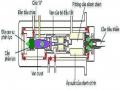
1. The cards
2. Oil filter
3. Oil pump
4. Safety valve
5. Oil filter
6. Thermostat
7. Oil cooler
8. Oil pressure gauge
9, 10, 11, 12 Oil pipeline
2.2. Operating principle
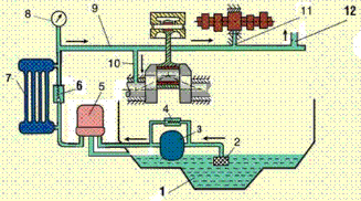
Figure 3.1
Lubricating oil is sucked from the crankcase through the primary filter and pushed up to the filter tank by the oil pump through the filter tank, the oil is cooled by the oil cooler and enters the main oil line from here the oil is led to lubricate the main necks of the crankshaft, the main neck of the camshaft, oil from the main neck of the crankshaft is led to lubricate the crankshaft thanks to the oblique groove, also from the main oil line there is an oil line to lubricate the swing arm shaft to extract lubricating oil for the distribution gear box. Lubricate the piston, cylinder, piston ring lubricates and cools the piston thanks to the splash of crankshaft oil, lubricates the push rod assembly, valves, and lifters thanks to excess oil brought down from the swing arm shaft.
3. Damage phenomenon, causes, remedies
3.1. Oil consumption
Cause:
- High engine speed:
+ Creating high temperature reduces the viscosity of oil, oil can easily pass through the gap between the piston ring and cylinder to the combustion chamber and be burned.
+ Increases the centrifugal force of the oil on the crankshaft and connecting rod bearings, causing the amount of oil adhering to the cylinder wall to increase.
+ Makes the oil ring vibrate, shake and lead oil to the combustion chamber. In addition, high speed makes the air vented through the crankcase at high speed carrying some oil out.
- Worn or jammed oil rings, poor oil scraping ability causes oil to rush into the combustion chamber and burn.
- The sealing ring at the valve guide head is hardened, losing its sealing ability, allowing oil to enter the combustion chamber (intake valve side) or escape with the exhaust gas (exhaust valve side).
3.2. Low oil pressure
Cause:
- Oil level is lower than specified.
- Safety valve spring damaged or adjusted at low pressure.
- Oil pump is worn.
- Oil line is cracked or broken.
- Oil line is clogged.
- Thin or unsuitable oil.
- The bearings are worn.
- Oil filter, oil filter gaskets leak or sensor is damaged.
3.3. Oil pressure too high
Cause:
- Safety valve is stuck.
- Safety valve spring is broken or adjusted at too high a pressure.
- Oil line is clogged or oil is too thick.
- Small bearing mounting gap.
4. Maintenance and repair of lubrication system
4.1. Disassembly and assembly sequence
4.2. Maintenance
4.2.1. Change lubricating oil
* Drain oil
Remove the oil drain bolt at the bottom of the crankcase, drain the oil into the oil pan, then screw the drain bolt back in, paying attention to installing the copper gasket for sealing.
Figure 3.2.1
* Oil change
Remove the dipstick and add oil to the crankcase to the specified level.
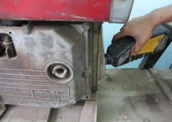
Figure 3.2.2
* Check oil level
Insert the dipstick and then take it out and observe the oil level on the dipstick.
The lubricating oil level in the crankcase must be close to the F mark on the gauge.
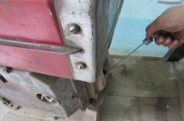
Figure 3.2.3a
Figure 3.2.3b
* Clean oil filter
- Remove the oil filter
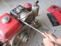
Use a wrench to remove the oil filter bolt from the engine body.
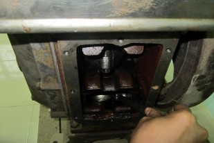
Figure 3.3.1a