Table 3.26. Relationship between tendon healing on postoperative magnetic resonance in the trauma group according to time level 87
Table 3.27. Relationship between tendon healing on postoperative magnetic resonance between male and female groups 87
Table 3.28. Results of tendon healing on postoperative ultrasound 88
Table 3.29. Comparison of magnetic resonance and postoperative ultrasound 89
Maybe you are interested!
-
 Research on diagnosis and endoscopic surgical treatment of benign adrenal tumors at Viet Duc Hospital in the period 1998 - 2005 - 20
 -
 Research on the treatment of seafood wastewater by electrocoagulation method combined with USBF - 19 tank
 -
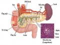 Research on the application of endoscopic ultrasound in the diagnosis of chronic pancreatitis - 2
 -
 Research on biological filtration technology with submerged materials in wastewater treatment technology using microbial arrays - 2
 -
 Research on the application of laparoscopic surgery in the treatment of rectal cancer - 16
Table 3.30. Comparison of post-operative UCLA results between men and women 89
Table 3.31. Comparison of post-operative ASES results between men and women 90
Table 3.32. Compare UCLA results across 90 age groups
Table 3.33. Comparison of postoperative ASES results between 90 year old groups
Table 3.34. Comparison of UCLA results between traumatic and non-traumatic causes 91
Table 3.35. Comparison of ASES results according to cause of injury 91
Table 3.36. Comparison of post-operative UCLA scores in the trauma group 91
Table 3.37. Comparison of postoperative ASES scores in the trauma group 92
Table 3.38. Comparison of UCLA results between tear classifications according to largest diameter 92
Table 3.39. Comparison of ASES results between tear classifications according to largest diameter 92
Table 3.40. Comparison of UCLA results between groups with biceps tendon injury and without biceps tendon injury 93
Table 3.41. Comparison of post-operative ASES score results between groups with biceps tendon injury and without biceps tendon injury 93
Table 3.42. Comparison of UCLA score results between the tenotomy and tenodesis group with the 94 biceps tendon preservation group
Table 3.43. Comparison of ASES score results between the tenotomy and tenodesis group with the 94 biceps tendon preservation group
Table 3.44. Anchor failure 96
LIST OF CHARTS
Chart 3.1. Age group characteristics of research subjects 74
Chart 3.2. Gender characteristics of research subjects 75
Chart 3.3. Shoulder ratio on injured side 75
Chart 3.4. Graph showing the relationship between tear size and number of microlesions using 82
Chart 3.5. Relationship between tear size and number of anchors used 82
Chart 3.6. Relationship between postoperative ASES score and degree of tendon healing 95
Chart 3.7. Relationship between post-operative UCLA score and degree of tendon healing 95
LIST OF FIGURES
Figure 1.1. Illustration of the upper humerus and the CX 3 tendon attachment
Figure 1.2. Illustration of three sides of a large bulb: S is the top edge, M is the middle edge, I is the bottom edge 4
Figure 1.3. Illustration of the shoulder blade and MCV viewed from the back 4
Figure 1.4. CX muscle tendons 5
Figure 1.5. Illustration of the left shoulder joint viewed from the front above 6
Figure 1.6. Anterior view of shoulder joint 7
Figure 1.7. Tendon attachment area below shoulder 8
Figure 1.8. Illustration of the attachment of CX muscles to the greater tuberosity 9
Figure 1.9. Posterior view of shoulder joint 10
Figure 1.10. Figure (A) depicts the anterior margin of the greater tuberosity; Figure (B) depicts the beginning of the achondral region 11
Figure 1.11. Illustrate the relationship between the supraspinatus and infraspinatus tendons with anatomical landmarks 12
Figure 1.12. Small circular muscle 13
Figure 1.13. Dynamic anatomy of the subacromial space 14
Figure 1.14. Diagram summarizing the mechanism of rotator cuff tears according to exogenous and endogenous pathways 15
Figure 1.15. Jobe's test 17
Figure 1.16. External rotation test with resistance 17
Figure 1.17. Gerber test 18
Figure 1.18. Bear hug test 18
Figure 1.19. Falling arm test 19
Figure 1.20. X-ray of the shoulder joint in anteroposterior position with a large tear CX shows the humeral head right next to the underside of the MCV bone 19
Figure 1.21. Illustration of calcification of the CX tendon of the shoulder joint seen in the Lamy 20 position
Figure 1.22. Complete tear of the supraspinatus tendon 21
Figure 1.23. Ultrasound illustration, white arrow shows complete supraspinatus tendon tear 21
Figure 1.24. The CX 22 completely ripped shapes
Figure 1.25. Patte classification on the degree of tendon contracture 22
Figure 1.26. Degree of fat degeneration in muscle according to Goutallier 23
Figure 1.27. Illustration of the similarity of the columnar anchor structure to the CX suture anchor. .. 26 Figure 1.28. Figure (A) Column anchor placed in a position far from the corner column. Figure (B) column anchor post
Placed near corner column 26
Figure 1.29. Illustration of angles 1 and 2 27
Figure 1.30. Illustration of one-row stitching technique 28
Figure 1.31. Details of the Mason-Alen suture technique used in open CX suture surgery.. 28 Figure 1.32. Illustration of the single-row suturing technique using the modified Mason-Alen method in endoscopy 30
Figure 1.33. Illustration of two-row stitching technique after completion of 31
Figure 1.34. Bridging suture technique used with 4 suture bridges and 2 suture bridges 32 Figure 1.35. Micro-lesion technique according to Milano 36
Figure 1.36. Microinjury technique according to Taniguchi, yellow arrow indicates fat droplet escaping 37
Figure 2.1. The figure depicts the conventions of terms used in anatomical research. Figure A, B viewed from the top of the humeral head, image C viewed from the outside 41
Figure 2.2. Separate specimens for dissection 42
Figure 2.3. Dissection along the tendon edge 42
Figure 2.4. (A) excision of the tendon body at the attachment site. (B) Mark the attachment area of each CX tendon and landmarks for reference 43
Figure 2.5. Tendon attachment area under the shoulder after removing the tendon body at attachment position 43
Figure 2.6. 3D scanning tools and specialized processing software 44
Figure 2.7. Illustration of positioning around objects using positioning stickers 44
Figure 2.8. Illustration of scanning the specimen after removing the synovial membrane... 45 Figure 2.9. Illustration of landmarks of the subscapularis tendon attachment area and KC to the edge of the articular cartilage 46 Figure 2.10. Illustration of how to measure landmarks to determine the area of attachment of the rotator cuff tendon to the greater tuberosity 47
Figure 2.11. Endoscopy equipment 51
Figure 2.12. Types of anchor threads used in research. From left to right, Corkscrew anchor thread, Twinfix Ultra HA and finally Y-Knot RC 51 thread anchor
Figure 2.13. Laparoscopic surgical instruments 52
Figure 2.14. Beach chair surgical position and patient's side lying position. . 52 Figure 2.15. Draw bony landmarks and entrances to the area below MCV 53
Figure 2.16. Enter the MCV lower compartment via rear entrance 53
Figure 2.17. Inflammation of the bursa below the MCV and abrasion of the coracoid ligament attachment 54
Figure 2.18. Burn the inflammatory tissue in the space below MCV 55
Figure 2.19. Exposing the bone spur at the anterolateral corner of the MCV, grinding and shaping the cavity below the MCV 55
Figure 2.20. After grinding, tendon adhesion area 56 is revealed
Figure 2.21. Measure and determine the location of the outer edge anchor based on KC indicators of attachment area anatomy and convergence point 56
Figure 2.22. Illustration of how to create micro-lesions in rows inside the anchor position 57
Figure 2.23. Micro-damage tool 58
Figure 2.24. Sequence of tendon suturing according to the modified Mason-Allen method 58
Figure 2.25. The drawing illustrates the relationship between tendon pull force direction and rotator cuff convergence point 59
Figure 2.26. Tie the vertical thread after tying the horizontal thread and the image after tying the thread 59
Figure 2.27. Creating micro-lesions after tying CX 60 sutures
Figure 2.28. Illustration of immobilization after RCX 60 surgery
Figure 2.29. Ultrasound image examining the biceps muscle112 63
Figure 2.30. Ultrasound image examining the subscapular muscle 64
Figure 2.31. Ultrasound image examining the supraspinatus muscle 64
Figure 3.1. Illustration of CX convergence point on photos and in 3D 68
Figure 3.2. Image of supraspinatus, infraspinatus, small round tendon adhesion area 69
Figure 3.3. Illustrates how to measure landmarks to determine the outer edge of the CX 69 tendon attachment area
Figure 3.4. Illustrate how to measure KC from the convergence point to the anterolateral points of tendon 71
Figure 3.5. Illustration of subscapular tendon attachment in comma, oval and triangle shape 71
Figure 3.6. Illustration of the outer border of the subscapularis tendon attachment above 72
Figure 3.7. Illustration of the tendon attachment area below the shoulder in the shape of a comma 72
Figure 3.8. Illustrate how to measure KCs from landmarks of the subscapular tendon attachment area 73
Figure 4.1. Image illustrating the expected location of the next anchor based on tendon direction and rotator cuff convergence point 98
Figure 4.2. Illustration of placement of CX suture anchors using the one-row method 100 Figure 4.3. Image of the micro-lesion hole in the first row inside the anchor placement... 101 Figure 4.4. Illustrates the relative positions of the points and edges of the above adhesion area
3-dimensional space 104
Figure 4.5. Illustration of the placement of two suture anchors in case of complete rupture of the subscapularis tendon, the first anchor is located on the curved prominence of the anterior border of the intertubercular groove, the lower anchor is on the lateral border of the lesser tuberosity 106
Figure 4.6. Illustration of damage to the biceps tendon >30% of the tendon and image after tendonectomy 108
Figure 4.7. Illustration of partial tear > 50% of thickness 112
Figure 4.8. Illustration of L-shaped, U-shaped tears and image of suturing the edge of the torn tendon with Vicryl 114 thread
Figure 4.9. Photo of nanofractures creation tool from Arthrosurface.com, and from several groups of authors 115
PROBLEM
Rotator cuff tear is a common disease in the elderly, it affects about 40% of the population over 60 years old. This disease causes pain and weakness in the shoulder, limiting the patient's shoulder joint function1,2 . Indicating and choosing the optimal treatment method for the patient depends on many factors related to the characteristics of the disease and the patient. In particular, it cannot be denied that surgery to repair rotator cuff tears is an effective method in treating the disease. It has the effect of reducing pain for the patient, restoring the stability of the shoulder joint and in the long term avoiding complications of osteoarthritis2. To achieve good results in the surgical treatment of rotator cuff tears requires the coordination of many factors, including subacromial space reconstruction and rotator cuff recovery, including maximum facial recovery. anatomy and ensuring the mechanical and biological strength of the tendon are considered to play a decisive role2 .
Regarding the anatomy of the rotator cuff, in 1992 Clark and Harryman published the first studies that meticulously evaluated the characteristics, thickness, and microstructure of the rotator cuff tendons, but did not clearly indicate the location of the rotator cuff. attachment of the rotator cuff tendon to the upper head of the humerus3. Then in 1998, Minagawa and his colleagues first gave a description of the attachment area of the supraspinatus and infraspinatus tendons and referred them to the edges of the greater humeral tuberosity. This is considered the first guide to orientation. for suture surgery to restore the rotator cuff attachment area4. Since then, there have been many studies on the anatomy of the rotator cuff, however, these studies have not been consistent in the shape and size of the attachment area of the rotator cuff, the way it attaches to the greater and lesser tubers and The relationship between these anatomic features of the rotator cuff tendon attachment area and the anatomical landmarks that can be applied during surgery to repair torn tendons has not been determined 4-10 .
The mechanical strength of the tendon after surgery depends greatly on the suturing technique. Among endoscopic tendon suturing techniques, the single-row suturing method is the first to be used. It was introduced in the 80s of the last century with advantages such as simplicity, shortening of surgical time as well as such as the number of anchors used, however, there are still disadvantages such as biomechanical limitations compared to double-row suturing and bridging methods11-14 . For more advanced