11
3.1.3 . Common errors, causes and remedies
TT
Name | Illustration | Reason | How to fix | |
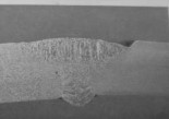
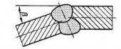
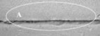
1 | Burnt edge weld. |
| - High welding speed, the welding torch has no stopping point at two amplitudes. - Large welding current | Adjust the speed moderately, oscillation has a stop point at two amplitudes. Do not choose too large current. |
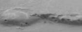
2 | Metal spatter |
| - Long arc, unstable current | - Shorten the arc distance. Adjust the current appropriately. |
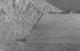
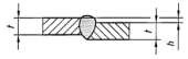
3 | Weld without fusion |
| Small current, fast welding head movement speed | Adjust welding current and speed accordingly |
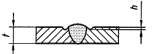
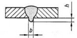
4 | Unfilled metal top edge |
| - The angle of the soldering iron is not correct. | - Adjust the angle and oscillation of the soldering iron |

Maybe you are interested!
-
 Division of common property between husband and wife according to the Law on Marriage and Family 2014 - 9
 -
 Division of common property of spouses during marriage under Vietnamese law - 14
 -
 Common Method Difference Test
 -
 1945 Common Chinese Characters - Education Publishing House - 6
 -
 Division of common property of spouses according to Vietnamese law - Practical application and improvement direction - 16
5
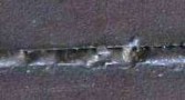
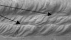
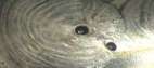
Air holes |
| - Small air flow - Impact of wind from the outside environment | - Increase protective air flow - Avoid being blown by the wind when welding |
3.1.4. Instructions for evaluating results
STT
Review content | Point | |
1 | Time | 94.0 |
2 | Operational attitude | |
3 | Objective external score | |
4 | Subjective external appearance score | 6.0 |
+ Time
Standard time | Difference from standard time | Points deducted | Note | |
60 | > 5% (3 minutes) | No rating |
+ Attitude, action
- In case a lecturer is determined to have violated one of the following grading criteria, points will still be deducted.
- In a scoring item, if the number of violations is > 2 times, the minus points will be counted as 2 times and the candidate will only need to be reminded to avoid making further mistakes.
Item
Scoring section content | Points deducted | |
1 | In case of dropping welding pliers, arc short circuit | 2 |
2 | When not to use protective glasses when grinding and shaping welding slag | 5 |
3 | In case of inappropriate protective clothing | 5 |
4 | In case of unsafe behavior (including cases where the candidate suffers minor injuries due to his/her own negligence) | 5 |
5 | Moderate damage to machinery and equipment. | 5 |
6 | In case the steps are not followed correctly when starting the device | 5 |
7 | In case of not following the steps to close the device at the end | 5 |
8 | In case of no industrial cleaning after the exam is finished | 5 |
In case of cutting off the welding wire end with length greater than 5mm | 2 |
9
+ Objective appearance
Nine content
Review section | Number of points deducted | |||
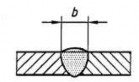
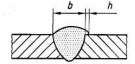
Cover | Weld Width
b = 10 mm | b=[9÷11] | b=(7÷9) Or b=(11÷13] | b>13 |
0 | 2 points /1mm in range | 4 points /1 mm | ||
Weld height h = 2.5 mm | 0 < h < 3 | h = [3÷ 6] | h > 6 | |
0 | 4 points/1 disability | 8 points / 1 disability | ||
Overflow
| h ≤ 1 | 1 < h ≤ 2 | h > 2 | |
0 | 2 points/1 defect | 4 points/1 disability | ||
Leave foot
| A disability | From the second disability | ||
5/1 disability | 7/1 disabled | |||
Surface hollow
| h ≤ 0.5 | 0.5 < h ≤ 1 | h > 1 | |
2 points/1 defect | 4 points/1 disability | 6 points/1 disability | ||
Angular deformation
| β ≤ 5 0 | β > 5 0 | ||
0 | Minus 2 points/10 ( from 6th degree deviation onwards) | |||
Offset | h ≤ 1 | h > 1 | ||
0 | Minus 2 points/1mm (from 2nd mm) | |||
| deviation onwards) | |||
Weld end | h ≤ 1 | h > 1 | ||
0 | Minus 2 points/1mm (from the 2nd mm deviation onwards) | |||
Burned weld toe
| Depth of burn marks on legs <0.5 | A disability | From the second disability | |
0 | 2 points/1 defect | |||
Depth of burn mark < 1 | A disability | From the second disability | ||
4 | 6 points/1 disability | |||
Depth of burn mark > 1 | A disability | From the second disability | ||
8 | 10 points / 1 disability | |||
Surface transition between welds
| Depth of burn mark < 0.5 | A disability | From the second disability | |
0 | 2 points / 1 disability | |||
Depth of burn mark < 1 | A disability | From the second disability | ||
4 | 6 points / 1 disability | |||
Depth of burn mark > 1 | A disability | From the second disability | ||
8 | 10 points / 1 disability | |||
Air holes
| Do not have | A disability | From the second disability | |
0 | 4 | 8 points / 1 disability | ||
Face | Base weld leg | Do not have | A disability | From disability |
| Monday | |||
0 | 5 | 7 | ||
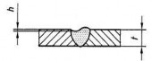
Back convexity
h = 2 | h < 3 | h = [3÷ 6] | h > 6 | |
0 | 5 points / 1 disability | 8 points / 1 disability | ||
Bottom surface | Disability, h ≤ 0.5 | Disability, 0.5< h ≤ 1 | Disability, h > 2 | |
0 | 2 | 5 | ||
Live welding wire | Do not have | 1 defect | From the second disability | |
0 | 5 | 6 points/1 disability | ||
Air leak
| Do not have | A disability | From the second disability | |
0 | 4 | 8 VND/1 disability | ||
Product surface | Arc fault | Do not have | Do not have | Do not have |
0 | 2 | 1 point / 1 mark | ||
Metal spatter on the surface | Completely removed | Other | ||
0 | 1 point/1 grain with diameter ≥ 0.25 | |||
Mechanical destruction | Do not have | A disability | From the second disability | |
0 | 2 | 3/1 disability | ||
bottom
+ Subjective appearance
Scoring section content | Minus points | Note | |
The surface, height and edge of the weld are uneven. | 2.0 |
Note:
1. Defect: is a short defect whose total length is not greater than 25mm in any 100mm of weld length or equal to 25% for welds with length less than 100mm.
2. End of weld recess: is the size from the bottom of the recess to the surface of the material.
weld.
3. Single air hole: is an air hole that can have 1 or more air holes in which the distance between
between 2 small air holes is smaller than the diameter of the small air hole.
3.2. Practical exercise 2: Welding a pipe with diameter Ф 90 at the vertical pipe axis position 2G.
3.2.1 Implementation sequence
1. Read drawings and technical requirements of welds
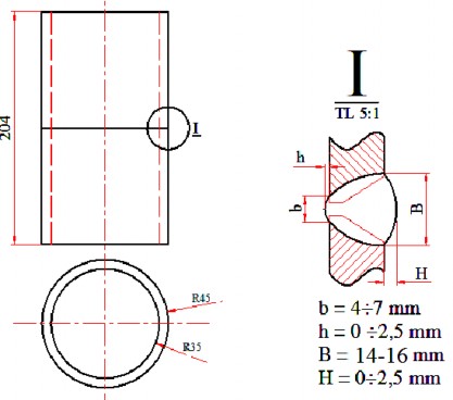
4.8.Welding drawings
2. Prepare equipment and tools
- Prepare MIG/MAG welding machine,
- Prepare CO2 gas bottle and install the meter on the gas bottle, connect the gas pipe from the bottle to the machine (use a wrench)
- Hand grinder, wire brush, file, anvil, hammer, ruler, wrench
3. Prepare welding materials
- Prepare welding wire. Insert the wire into the machine and adjust the length of the protruding part of the welding wire: 12÷ 15 mm
- Prepare gas, open valve to check the amount of gas in the bottle
- Welding blank: Cut steel pipe blank. Clean the edge to be welded by filing or grinding.
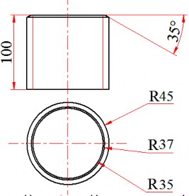
Figure 4.9. Welding workpiece size
4. Determine and select welding parameters (according to table 1)
- Adjust welding current: 110 ÷ 120 A, voltage 220 ÷ 22 V
- Adjust the protective gas flow rate 8÷ 12 liters/minute
- Check the circulation of the shielding gas: Press the soldering iron switch to check.
5. Fixing and attaching joints
- Place the tube blank on the centering fixture (v-block), adjust the gap to 3.2 ÷ 4 mm or mount the blank as shown.
- The tack weld must be firm. The tack weld should not be welded directly to the lining weld edge, but should be tack welded to the outer part of the pipe thickness (as shown in the figure). The deviation between the two pipe edges should not exceed 1.6 mm.
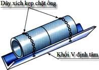
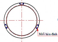
Figure 4.10.a-Alignment, clamping Figure 4.10.b-Location of the attachment joints
6. Mount the workpiece in the correct welding position
- The welding workpiece must be securely mounted in the correct horizontal welding position.
(pipe generator perpendicular to the projection plane, position 2G).
Figure 4.11- Workpiece clamping at position 2G
7. Adjust the welding mode parameters
Based on the material thickness and welding wire diameter, select and adjust welding parameters according to the welding mode parameter table on the welding machine.
- Adjust welding current to about: 100 ÷ 110 A, voltage 20 ÷ 22 V
- Adjust the protective gas flow rate 8÷ 12 liters/minute
8. Welding the lining:
- Create an arc at any position 10 ÷ 15 mm away from the tack weld. When you see the weld pool forming between the two edges of the workpiece, move the welding torch in a straight line. When the keyhole starts to form, proceed with horizontal oscillation.
- The soldering iron swings horizontally in a sawtooth or circular pattern, depending on the width of the mounting gap.
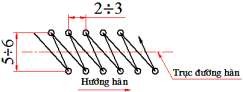
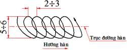
Figure 4.5a-Sawtooth oscillation
Figure 4.5b-Oscillation in a deviated circular pattern
- The angle of the welding torch relative to the tangent of the weld axis at the welding point
welding direction from 65 0 85 0 (travel angle) and welding torch compared to the generator line of the pipe below at the corner welding point from 65 0 85 0 (working angle).
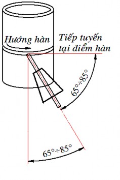
Figure 4.13.- Welding torch angle
- When oscillating, the welding torch must stop at the oscillation amplitude to ensure penetration and metal filling the weld edge, stopping at the upper amplitude greater than the lower amplitude.