information about allowed services, areas where roaming is not allowed, and information about additional services such as call forwarding status and number.
- MSC/VLR is the MSC switch and VLR database to provide circuit switched services to the UE at its current location. The function of MSC is to use CS (Channel Switch) transactions. The function of VLR is to keep a copy of the profile of the visiting user as well as the exact location of the UE in the serving system. The network part accessed via MSC/VLR is called the CS area.
- GMSC is the switch at the UMTS PLMN connection point with the external CS network.
- SGSN has the same function as MSC/VLR but is used for PS (Packet Switch) services. The network part accessed via SGSN is called PS area.
- GGSN has the same function as GMSC but is related to PS service.
2.5 . User Equipment ( UE )
UE consists of two parts:
- Mobile Equipment (ME) is a radio terminal used for radio communications over the Uu interface.
- UMTS Subscriber Identity Module (USIM) is a smart card that contains subscriber identity information, performs authentication algorithms and stores authentication keys and some subscriber information needed by the terminal.
- 2.6. Open interfaces
- Cu interface: is the interface between the USIM smart card and the ME. This interface follows a standard format for smart cards.
- Uu interface: is the radio interface of W-CDMA. Uu is the interface through which the UE accesses the fixed elements of the system, so it is the most important open interface in UMTS.
- Iu interface: connects UTRAN to CN. Similar to the corresponding interfaces in GSM: A (circuit switched) and Gb (packet switched). Iu provides operators the possibility to equip UTRAN and CN from different manufacturers.
- Iur interface: allows soft handover between RNCs from different manufacturers.
- Iub interface: connects a Node B to an RNC. The Iub interface allows for competition between manufacturers.
2.6 . Transmission network
Transmission over the UTRAN system will be based on ATM. There has been discussion as to whether the UTRAN standard should include a transport layer or whether it should be open. That is, at this point some equipment vendors want it to be open to allow operators freedom of choice. The core network protocol will be used for transmission between the radio transceiver stations and the switching center via the base station controller (Iu, Iub). The use of ATM allows a huge number of packets to be transmitted efficiently with minimal delay. An ATM protocol allows about 300 calls to be transmitted simultaneously on a single E1/T1 line. ATM is also suitable for networks with a mix of circuit-switched and packet-switched traffic.
Packet traffic will increase greatly in the future and a packet-switched network is essential. ATM tends to be standardized and used as a data transport and a new ATM compatibility layer - AAL2, is proposed to be standardized to support delay-sensitive packets (packets carrying voice information).
As mentioned, for existing networks, some vendors believe that ATM is unnecessary and are proposing an alternative that uses IP directly over SONET/SDH rather than IP over ATM. This could result in a lower cost network that takes advantage of spread spectrum techniques. However, to date, IP has not proven to be a ready standard that can securely handle real-time, delay-free communications. Nor has it proven to be capable of handling circuit-switched traffic.
In case we have to rely completely on IP, it will be improved or circuit switched traffic will not be needed for UMTS. Then all voice information and real-time applications will be transported over IP using the H.323 protocol currently used for Voice Over IP and Multimedia.
CHAPTER 3
TECHNICAL AND TECHNOLOGICAL CONDITIONS FOR THE 3G TRANSITION PROCESS
3.1 . 2G to 3G conversion capability
3.1.1 . Analysis of conversion possibilities
The four main 2G cellullar technologies today are:
- GSM system: as the name means global system for mobile phones, is the first 2G system to appear, launched in 1992. GSM is based on circuit switching technology. Low-speed data transmission service (<9.6 kbps) was provided from the beginning of the system's deployment and was mainly used for transmitting e-mail from laptop computers.
- PDC system: used in Japan, uses TDMA technology.
- cdmaOne (IS-95): based on narrowband CDMA technology. The system has become very popular in Korea and North America.
- Apart from the Japanese PDC system, which is concerned about not being able to develop the market abroad, it did not upgrade further and instead deployed the new 3G technology directly. Other systems have plans to convert to 2.5G and 3G. An overview of the conversion options is shown in the following figure:
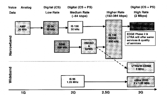
Figure 3.1 The process of conversion from 2G to 3G system
- GSM will remain the main system of mobile information services in Vietnam.
- 1800 spectrum band is needed to increase capacity.
- Network design and planning will play a key role in improving network quality.
- Charging for GPRS is a prominent issue. Up to now, there has been no common standard.
- Charging of GPRS services needs to be carefully considered. There are many issues associated with charging based on traffic.
- EDGE is the evolutionary path to the third generation and is also a complement to UMTS.
- UMTS is the European proposal for third generation mobile communications. The air interface has been chosen and will be based on wideband CDMA (W-CDMA) technology.
- It is expected that Asian countries currently operating GSM systems will follow the European 3G standard.
- For the GSM network currently operating in 168 countries providing services to 500 million subscribers, deploying the UMTS standard on the GSM system is completely in line with natural laws.
3.1.2 Conditions and issues for the conversion steps
The transition from GSM to 3G network will involve three main aspects, which are carried out according to the diagram:
Technical transformation
Network Transformation
2G
3G
Service Transformation
Figure 3.2 . Development aspects
3.1.2.1 . Technical transformation
Technical transformation is the development path that specifies the method to deploy network elements and the type of technology to implement that technology. It is a direct development step following general trends in technology.
Because network elements are the building blocks of the network, the technical transformation should theoretically correspond to the network evolution. In phase one, due to the open nature of the interfaces defined in the system specification,
3G networks can be combined from many types of equipment from many different manufacturers. Technical transformation can handle this, but with the difference in speed and specific implementation steps in the combination of equipment between different manufacturers and the requirement to adapt to changes in 3G technical indicators, in many cases if not carefully considered, the results may not be as expected.
3.1.2.2 . Service transformation
Unlike technical migration, service migration is based on user needs, which can be real or imagined. Sometimes network operators and equipment manufacturers deliver services that exceed subscriber expectations. Obviously, if these two factors are not compatible, the mobile communication services business will be difficult.
3.1.2.3 . Network transformation
The GSM specification ensures the openness of the interfaces that determine the standard composition of the GSM system. Because of this open interface, network operators can use different network equipment from different GSM network equipment suppliers. The openness of the interface is expressed in that it strictly defines the system functions that are performed at this interface, and clearly defines which functions are allowed to be used by the operator within the network on both sides of this interface.
3.2 . Existing GSM system structure
The network is geographically divided into three smaller networks, operated by different centers. The current network will be the basis when migrating to a network with higher data rates. In terms of configuration, for simplicity, the overall network can be divided into
into four main subsystems NSS (Network Subsystem), BSS (Base Station Subsystem), NMS (Network Management Subsystem), MS (Mobile Station):
Network Management System (NMS )
BSS
NSS
BTS
BSC
TRAU
MSC/VLR
ISDN
GMSC
PSPDN
PSTN
X25
HLR/AuC/EIR
CSPDN
Um A
MS
Maybe you are interested!
-
 Completing the management and supply of raw materials at the training equipment manufacturing factory X55 - 7
 -
 Current Status of Facilities Management, Ensuring Equipment for Self-Study Activities
 -
 Completing the management and supply of raw materials at the training equipment manufacturing factory X55 - 5
 -
 Research on some solutions to improve the quality of human resources at Khanh An Preschool Education Equipment Production and Trading Company Limited - 1
 -
 Working Principle Diagram Of Continuous Butter Making Equipment
Figure 3.3. Current GSM network structure
3.2.1 . BSS base station control subsystem
All calls are connected through the BSS. The Base Station Controller (BSC) is the main part of the BSS and it controls the radio network. The BSC maintains the connection with the MS and connects to the NSS. The Base Transceiver Station (BTS) is the part of the network that maintains the Um interface. The Transcoding and Rate Adaptation Unit (TRAU) is a part of the BSS that maintains the coding rate.
The open interface between the MS and the BSS is the Um interface which provides radio access between the MS and the mobile network based on the GSM 900 standard with 8MHz spectrum. This spectrum is sufficient to carry voice capacity over the network with good quality. As voice and data capacity increase, increasing radio spectrum is necessary to ensure good voice quality and increase data transmission speed.