LESSON 04: SPIRAL GROOVE MILLING
4.1. Milling right helical groove
Time to complete: 6 sessions
Previous lesson name:
................................................................ .
Performed from date..................... to date ....................................
I. Teaching facilities and equipment
1.1. Teaching aids
Lesson plans, outlines, chalk, projector, drawings, ...
1.2. Equipment, tools, materials
T
T
Name and specifications of the device, tools; raw materials, consumables | Single taste | SL | Note | Additional | |
1 | Device | ||||
Universal milling machine 6X332B | Female | 02 | Continued use | ||
Spare parts for milling machine | Set | 02 | Continued use | ||
Universal indexing head | Female | 02 | Continued use | ||
Universal indexing head spare parts | Set | 02 | Continued use | ||
2 | Tool | ||||
Dial gauge + holder | Set | 02 | Continued use | ||
Caliper 1/50, L=200 | Female | 10 | Continued use | ||
Wrench set from 8÷24mm | Set | 01 | Continued use | ||
Ruler 200 | Female | 02 | Continued use | ||
Universal angle gauge | Female | 02 | Continued use | ||
3 | Materials (for 01 student) | ||||
Steel billet Ф26, L=200 | Female | 01 | Cancel | ||
End mill Ф6 | Son | 01 | Cancel | ||
HD50 Oil | Liter | 01 | Cancel | ||
4 | Other |
Maybe you are interested!
-

 Strengthening Facilities and Equipment for Teaching Experiential Natural Science Subjects
 -
 Facilities and Equipment for Teaching English in Secondary Schools in Phu Tho Town
 -
 Current Status of Facilities Management, Ensuring Equipment for Self-Study Activities
 -
 Management of the use of teaching equipment in secondary schools in Ninh Giang district, Hai Duong province - 15
 -
 Measures to Mobilize Educational Forces to Invest in Facilities and Purchase Equipment by Principals of Secondary Schools in Quang Yen Town
II. Lesson implementation
2.1. Lesson objectives
After completing this lesson, students will be able to:
+ About knowledge
- Calculate the basic parameters of spiral grooves
- Select the gears to install the differential
+ About skills
Fix the cutter and adjust the machine to mill spiral groove details to meet technical requirements.
+ About attitude
- Serious and self-disciplined in the learning process.
- Ensure labor safety and environmental hygiene.
2.2. Lesson content
In the mechanical field, especially the machine manufacturing industry, we encounter many parts with spiral grooves such as spiral milling cutters, spiral drills...


Figure 4.1: Detail with spiral groove
d
To form spiral grooves, there are many different machining methods, including spiral groove milling method.
The principle of spiral groove milling method is that when the workpiece rotates one revolution, the machine table moves an amount equal to the spiral step; that is, to create a spiral groove, the part must simultaneously perform two movements: the movement
continuous rotation and axial translation.

L | |
d |
Figure 4.2: Spiral groove brushing diagram
2.2.1. Technical requirements of right-handed spiral groove
- Ensure correct twist angle α ±30'
- Ensure the accuracy of groove size BxH
- Ensure groove rib roughness Ra = 2.5 mm.
- Enough grooves on the part
2.2.2. Basic parameters of right-handed helical groove
- Top diameter: D e
- Foot diameter: D i
- Average diameter: d
- Groove width: B
- Groove height: H
- Twist angle: α
- Twist length: L
2.2.3. Calculation of basic parameters of right-handed helical groove
- Average diameter: d = D e – H
- Twist length: L = п.d.cotgα
- Calculate the transmission ratio i to find the gears for the differential bridge:
i N . T
L
A z 1 z 3
4
zz
2
In which: N: universal indexing head characteristic (N=40)
T: vertical screw pitch of milling machine table (T=6)
2.2.4. Right helical groove milling procedure
Step 1: Calculate the length of the twist
L = ο.d.cotgα
Step 2: Calculate the transmission ratio i to find the gears z 1 , z 2 , z 3 , z 4 to install the gear bridge
i N . T
L
A z 1 z 3
4
zz
2
Step 3: Install the gear bridge
Gear bridge connects from universal dividing head IV shaft to the vertical lead screw shaft of the milling machine table.
Gear z 1 is tightly fitted to the lead screw shaft along the milling machine table
Gear z 4 is tightly fitted to the indexing head shaft IV (sub-shaft).
Milling the spiral groove in the right direction so we install the gear bridge as an odd bridge, meaning the number of shafts connecting from the active shaft to the passive shaft is an odd number.
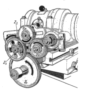
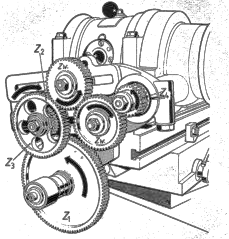
Figure 4.3: Installing the spiral grooved differential gear bridge
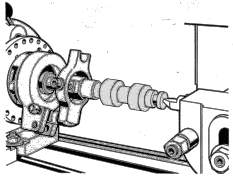
Step 4: Mount the workpiece onto the machine
The workpiece is clamped at one end into the 3-jaw chuck of the indexing head, the other end against the tailstock center of the indexing head or both ends against the center transmitting the torque by clamping speed.
Step 5: Knife holder
- When cutting with a milling cutter, the cutter shaft should be perpendicular to the machine table.
- When cutting with a disc milling cutter on a vertical milling machine, tilt the machine head carrying the cutter at an angle equal to the required twist angle, the rotation direction of the machine head is clockwise.
- In case of cutting with a disc milling cutter on a horizontal milling machine, the machine
The milling machine must be able to rotate the machine table at an angle equal to the twist angle (for example, the 6P82 milling machine can rotate the machine table).
Step 6: Adjust the machine
Machine adjustment process for milling right helical grooves
similar to when

Figure 4.4: Gear mounting position on the differential bridge
Adjusting the machine to mill straight grooves also requires adjusting the cutter to the center of the workpiece and taking the cutting depth. The difference is that when machining a part that is both rotating and translating, the replacement gear set will rotate, so the pin that fixes the dividing disc to the head body must be loosened.
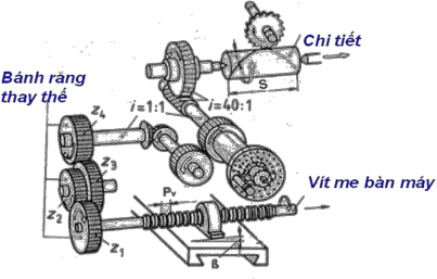
Figure 4.5: Diagram of spiral groove milling process

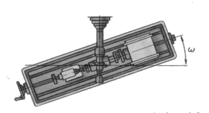
Figure 4.6: Rotating the machine table when milling spiral grooves on a horizontal milling machine
The graduation and the handwheel locking pin of the graduation head must be inserted into the hole of the division disc.
When milling multiple helical grooves on the same shaft, after finishing the first groove, remove the locking pin and perform normal division to mill the second groove. Do the same until all the grooves are finished (for example, when milling helical gears).
Step 7: Finish
Check all dimensions one last time then disassemble the product.
2.2.5. Types of failures, causes, and prevention
TT
Failure mode | Reason | Prevention | |
1 | Wrong twist direction | - Wrong gear bridge installation Incorrect axle number | - Reinstall the gear bridge |
2 | Incorrect twist angle | - Calculate the wrong gear ratio - Select gear with incorrect calculated number of teeth | - Recalculate - Select the correct number of teeth of the calculated gear |
3 | Groove side roughness not achieved | - Selecting the wrong cutting mode - Dull knife - Technology system vibration | - Reselect mode - Replace or sharpen the knife - After moving the machine table to the next tooth groove, tighten the machine table brake levers in the vertical and horizontal directions. back |
2.3. Organizing skill training
1. Exercise
Milling right spiral groove on workpiece with size Ф26, L=200; α=15 0 ; B=6; H=3
Requirement: 2 students/1 product
2. Implementation sequence (implementation process table)
TT
Steps to take | Instructions for implementation | |
1 | Step 1: Calculate the parameters of the spiral groove | - Average diameter: d = 26 – 3 = 23 - Twist length L = п.d.cotgα L = 3.14 x 23 x cotg15 0 = 3.14 x 23 x 3.732 = 269.66 |
2 | Step 2: Calculate the gear ratio i | i N . T 40.6 0.89 8 100 40 L 269.66 9 50 90 |
3 | Step 3: Install the gear bridge
| - Gear z 1 = 100 is tightly mounted on the vertical lead screw shaft of the milling machine table - Gear z 4 = 90 is tightly mounted on shaft IV (sub-shaft) indexing head - Gear z2 = 50, z3 = 40 is mounted on the intermediate shaft as shown in the diagram below. |
4 | Step 4: Select cutting mode | - Cutting depth t = H = 3 mm - Feed rate S= 40 mm/min - Number of main shaft revolutions n=500÷600 rpm |
Step 5: Mount the workpiece onto the machine
| - One end of the workpiece is clamped into the 3-jaw chuck of the indexing head, the other end is against the center of the indexing head's tailstock, or both ends are against the center transmitting the torque by clamping speed. - Check radial runout and end face runout of the workpiece | |
6 | Step 6: Adjust the machine
| - Adjust the tool center to coincide with the center of the workpiece as when milling a straight groove on the shaft. - Take the cutting depth t=3mm to cut the first spiral groove, then return the knife to the original position and perform the second groove cutting division (if any) similar to cutting the first groove... - When adjusting the spiral groove cutting machine, be careful to ensure the safety of the gear bridge and the operator. |
7 | Step 7: Finish | - Final check of dimensions together before removing the product |
5
2.4. Self-study
1. Calculation for milling right spiral groove on workpiece with size Ф38, L=200; α=15 0 ; B=8; H=4
2. Calculation for milling right spiral groove on workpiece with size Ф38, L=200; α=25 0 ; B=8; H=4
LESSON 04: SPIRAL GROOVE MILLING
4.2. Milling of left spiral groove
Time to complete: 6 periods Previous lesson name:
................................................................ .
Performed from date..................... to date ....................................
I. Teaching facilities and equipment
1.1. Teaching aids
Lesson plans, outlines, chalk, projector, drawings, ...
1.2. Equipment, tools, materials
T
T
Name and specifications of the device, tools; raw materials, consumables | Single taste | SL | Note | Additional | |
1 | Device | ||||
Universal milling machine 6X332B | Female | 02 | Continued use | ||
Spare parts for milling machine | Set | 02 | Continued use | ||
Universal indexing head | Female | 02 | Continued use | ||
Universal indexing head spare parts | Set | 02 | Continued use | ||
2 | Tool | ||||
Dial gauge + holder | Set | 02 | Continued use | ||
Caliper 1/50, L=200 | Female | 10 | Continued use | ||
Wrench set from 8÷24mm | Set | 01 | Continued use | ||
Ruler 200 | Female | 02 | Continued use | ||
Universal angle gauge | Female | 02 | Continued use | ||
3 | Materials (for 01 student) | ||||
Steel billet Ф26, L=200 | Female | 01 | Cancel | ||
End mill Ф6 | Son | 01 | Cancel | ||
HD50 Oil | Liter | 01 | Cancel | ||
4 | Other |
II. Lesson implementation
2.1. Lesson objectives
After completing this lesson, students will be able to:
+ About knowledge
- Strengthening the right helical groove milling method
- Calculate and install gear set to mill left spiral groove