Comment:
- If there is an all-pass digital filter, a band-pass digital filter and a band-stop filter with the same phase response, we have the following relationship:
j j j
H bs ( e ) H ap ( e ) H bp ( e )
Maybe you are interested!
-
 Amplitude Response Characteristics of a Linear Phase Fir Filter in Example 5.7
 -
 Design of Linear Phase Fir Filter Using Window
 -
 Characteristics of Business Activities and Business Management Organization at Small and Medium Enterprises in Vietnam
 -
 Characteristics of Activities During the 1000th Anniversary of Thang Long
 -
 Solutions for Investment Implementation Phase
j
j
j
H bs ( e ) : is the frequency response of the band-stop filter. H ap ( e ) : is the frequency response of the all-pass filter. H bp ( e ) : is the frequency response of the band-pass filter. In the n-domain we also have:
h bs ( n ) h ap ( n ) h bp ( n )
(4.10)
(4.11)
4.1.3. Practical digital filters
All ideal digital filters have rectangular frequency-amplitude responses, so their impulse responses are non-causal sequences of infinite length, so ideal filters are not possible.
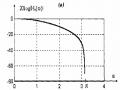
The frequency response of a practical digital filter is often undulating in the passband and stopband, with steep slopes on both sides as shown in Figure 4.9: .
j
H bp ( e )
p
0
c p
Figure 4.9. Frequency amplitude response of a practical low-pass filter To characterize a practical filter, the following parameters are used:
1. Filter type: Low pass, high pass, band pass, stop band
2. Bandwidth limiting frequency c
3. Stopband frequency p
(or f c ).
(or f p ).
4. Transient bandwidth
p p c
(or f p )
H bp ( e ) 1
j
5. Passband jitter 1 . In the passband, the frequency-amplitude response
j
H bp number ( e )
must satisfy condition 1 1 1
j
6. The undulation in the stop band 2 . In the stop band the frequency amplitude response
j
H bp number ( e )
must satisfy the conditions:
H bp ( e )
2
Actual filter has
p , 1 and 2The smaller the frequency amplitude characteristic, the larger the frequency amplitude characteristic.
almost rectangular in shape, so the signal selectivity is better.
4.2. Pulse characteristics of linear phase FIR digital filter
FIR digital filters have a finite impulse response h(n) , so the system transfer function
To be :
N 1
H z h ( n ) z nn 0
Since the impulse response h(n) is finite, the FIR filter is always stable, which means that all
The poles of the system function H(z) lie within the digital unit circle of the FIR digital filter:
z 1 . Frequency response
N 1
H ( z ) h ( n ) e j n A ( e j ) e j ( )
n 0
For linear phase FIR digital filters:
(4.12)
In which and are constants , and is the propagation time of the signal through the filter:
d
d
(4.13)
From this we can see that all frequency components of the signal passing through the linear phase FIR digital filter are delayed equally, so the signal is not distorted.
Because H ( e j )
cyclical
2 So we only study the boundary response.
frequency
H ( e j ) and phase ( ) when
( )
or (0 2 ) .
On the other hand, if the digital filter has an impulse response h(n) that is a real sequence, then according to the properties of the Fourier transform we have:
H( e j )
H( e j )
So
H ( e j )
is an even and symmetric function, and
( )
is odd and antithetical
symmetric. Therefore, when the impulse response h(n) is a real sequence, it is only necessary to study the digital filter in
interval (0 ) .
According to (4.12), there are 2 cases of linear phase FIR filter:
1. 0 ( )
2. 0 ( )
a. Case 0 ( )
Expanding Euler's formula, the frequency response is expressed as:
On the other hand there are:
H(e j ) A(e j )e j A(e j ) cos( ) j sin( )
H(e j ) A(e j )cos( ) jA(e j ) sin( ) (4.14)
N 1 N 1
H(e j ) h(n)e j n h(n). cos( n) j sin( n)
n 0 n 0
N 1 N 1
H(e j ) h(n).cos( n) j h(n) sin( n)
n 0 n 0
From (4.14) and (4.15) we have:
(4.15)
N 1
A ( e j ) cos( ) h ( n ) cos( n )
n 0
N 1
A ( e j ) sin( ) h ( n ) sin( n )
n 0
Infer:
N 1
h ( n ) sin( n )
N 1
tg ( ) n 0
h ( n ) cos( n )
n 0
Since sin(0) = 0 and cos(0) = 1 , we can rewrite the above expression as:
N 1
h ( n ) sin( n )
N 1
tg ( ) n 0
h (0) h ( n ) cos( n )
n 1
From here there are 2 cases 0 is a zero-phase filter, and 0
N 1
h ( n ) sin( n )
N 1
With 0 : tg (0 ) n 0 0
h (0) h ( n ) cos( n )
n 1
That is :
ì 0 h( n ) = ì
yes yes
ïî ¹
" n ¹ 0
.
0 n = 0
Such a filter is impractical and impossible to implement, because the signal transmitted through the filter is always delayed, even if the delay time is minimal.
With 0
sin( )
N 1
h(n).sin(n )
tg( ) n 00
cos( )
N 1
N 1
h(n).cos(n )
n 0
N 1
Or:
tg ( ) sin( ) h ( n ) cos( n ) cos( ) h ( n ) sin( n )
n 1 n 0
N 1 N 1
So:
tg ( ) sin( ) h ( n ) cos( n ) cos( ) h ( n ) sin( n ) 0
n 1 n 0
Continuing to transform trigonometry will get the equation:
N 1
h ( n ) sin ( n )
n 0
The above Fourier series equation has a unique solution at:
N 1
2
(4.16)
(4.17)
And: h(n) = h(N-1-n) with n (0, N-1) (4.18)
According to (4.18) the impulse response h(n) of the linear phase FIR digital filter when the array is symmetric.
0 is
- When 0
- When 0
Example 1 :
and N is odd, called a linear phase FIR digital filter of the first type.
and N is even is called a type 2 linear phase FIR digital filter.
Linear phase FIR digital filter has
h(2) =2 .
( ) , with N =5 and h(0) = -1, h(1) = 1,
Find and plot the impulse response h(n ) of the filter.
Prize :
Because 0 and N is odd so this is a linear phase FIR digital filter of the first type. According to (4.17) we have:
N 1 5 1 2
2 2
According to (4.18) we have: h(n) = h(5-1-n) = h(4-n)
So :
Impulse response graph h(n) :
h(4) = h(0) = -1
h(3) = h(1) = 1 h(2) = 2
h ( n )
2
1
-1 1 2 3 n
Figure 4.10. h(n) of a linear phase FIR filter of the first type.
Example 2 :
Linear phase FIR filter has ( )
, with N = 4 and h(0) = -1, h(1) = 1.
Find and plot the impulse response h(n) of the filter.
Prize:
Because 0 and N is even so this is a type 2 linear phase FIR filter.
According to (4.17) we have:
N 1 4 1 1.5
2 2
According to (4.18) we have: h(n) = h(4-1-n) = h(3-n)
So :
Impulse response graph h(n):
h(3) = h(0) = -1
h(2) = h(1) = 1
1 1
-1
0 1 2 3
n
h ( n )
Figure 4.11. h(n) of a type 2 linear phase FIR filter.
Comment :
- Type 1 and type 2 linear phase FIR digital filters have symmetric impulse responses h(n) like ideal filters.
- The center of symmetry of h(n) coincides with the sample at n = .
+ If N is odd then is an integer and the axis of symmetry h(n) coincides with the sample at
N - 1
n = .
2
N - 1
+ If N is even then is a decimal and the axis of symmetry lies between the two denominators.
N
in
n = and
2
n = .
2
b. Case 0 ( )
By the same transformation as in the above case, we get.
h ( n ) sin ( ) 0
The above Fourier equation has only one solution at:
(4.19)
N 1 ;
2
2
(4.20)
h(n) = -h(N-1-n) with n (0, N 1) (4.21)
According to (4.21), the impulse response h ( n ) of the linear phase FIR filter in the case
0 is an antisymmetric sequence.
- When 0
- When 0
Example 3:
and N is odd, called a type 3 linear phase FIR digital filter. and N is even, called a type 4 linear phase FIR digital filter.
Given a linear phase FIR filter with ( ) , with N=7 and h (0) = -1,
h (1) = -0.5 and h (2) = 1.5 .
Find and plot the impulse response of the filter.
Prize:
Because 0 and N is odd so this is a type 3 linear phase FIR filter.
According to (4.20) we have:
N 1 7 1 3
2 2
According to (4.21) we have: h(n) = -h(7-1-n) = -h(6-n)
So :
Impulse response graph h(n):
h(6) = -h(0) = 1
h(5) = -h(1) = 0.5
h(4) = -h(2) = 1.5 h(3) = 0
h ( n )
1.5
1
0 1
-0.5
-1
2
3
4
-0.5
5
6
n
-1
Figure 4.12. h(n) of a type 3 FIR filter.
Example 4 :
Given a linear phase FIR filter with ( ) with N=4 and h(0) = -1, h(1) = 1 Find and plot the impulse response of the filter.
Prize:
Because 0 and N are even so this is a type 4 linear phase FIR filter
According to (4.20) we have:
N 1 4 1 1.5
2 2
According to (4.21) we have: h(n) = -h(4-1-n) = -h(3-n)
So :
Impulse response graph h(n):
1
1
0 1 2
-1
3
-1
n
h ( n )
h(3) = -h(0) = 1
h(2) = -h(1) = -1
Figure 4.13. h(n) of a type 4 FIR filter.
Comment :
worthy
- Type 3 and type 4 linear phase FIR digital filters with opposing impulse response h(n)
-The antisymmetric center of h(n) is at n = .
+ If N is odd then is an integer and the antisymmetric center h(n) coincides with the denominator at
N - 1
n = and there h(n) = 0 .
2
+ If N is even then is a decimal and the anti-symmetric center lies between the two samples at
N - 1 N
n = and
2
n = .
2
Thus, there are four types of linear phase FIR filters with ( ) :
- Type 1 filter:
- Type 1 filter:
- Type 1 filter:
- Type 1 filter:
0 , N is odd , impulse response h(n) is symmetric.
0 , N is even, the impulse response h(n) is symmetric.
/ 2 , N odd , impulse response h(n) is antisymmetric.
/ 2 , N is even , the impulse response h(n) is antisymmetric.
4.3. Frequency characteristics of linear phase FIR digital filter
4.3.1. Frequency characteristics of type 1 linear phase FIR filter
Linear phase FIR filter has ( ) and N is odd, the frequency response is:
N 1
H ( e j ) h ( n ) e j n A ( e j ) e j n 0
Because N is odd, expand the above expression into the sum of 3 components:
H ( e j )
N 1
h ( n ) e j n h N 1 e j
N 1
2
N 1
h ( n ) e j n
n 0
2
n N 1
2
Change the variable to the third part, let m = (N-1-n) => n = (N-1-n),
When
n N 1
then
m N 1
1
2
1
2
When n = (N-1) then m = 0 :
N 1 1
N 1
H ( e j ) 2
h ( n ) e j n h N 1 e j 2
h ( N 1 m ) e j ( N 1 m )
0
2
n 0
m N 1 1
2
Reverse the index and change the variable of the 3rd component according to n :
N 1 1
N 1
N 1 1
H ( e j ) 2
h ( n ) e j n h N 1 e j 2
2
h ( N 1 n ) e j ( N 1 n )
n 0
2
n 0
Since the linear phase FIR filter of type 1 has h(n) =h(N-1-n), then:
N 1
N 1 1
H ( e j )
N 1
j
2
2
h ( n ) e j n e j ( N 1 n )
(4.22)
h e
2
n 0
j N 1
j N 1 n
j N 1 n
In which: e j n e j ( N 1 n ) e
2 e 2
e 2
j N 1
N 1
Or:
e j n
e j ( N 1 n )
2 e
2 cos
n
Therefore (4.22) is reduced to the form:
N 1
N 1 1
2
N 1
j N 1
j 2
N 1
j 2
H ( e
) h
e 2
2 h ( n ) cos
n e
Or:
2
n 0
2
N 1 1
N 1
N 1
j
N 1 2
N 1
j
2
j
2
H ( e
) h
2 h ( n ) cos
n e
e
2
n 0
2