For any choice in the above cases, we define:
b = 2 sin
Maybe you are interested!
-

 Characteristics of the Practice of the Right to Prosecute During the Investigation Stage of a Case of Intentionally Causing Injury or Harm to the Health of Another Person.
 -
 Study on natural regeneration characteristics of Lim xet tree species Peltophorum tonkinensis A.Chev in Lam Binh district, Tuyen Quang province - 13
 -
 General Operating Characteristics Curve of a Group of Generators
 -
 Management experience in building a national standard secondary school in Cam Pha city, Quang Ninh province - 1
 -
 Pulse Characteristics of Linear Phase Fir Digital Filter
⎛ M 1 n ⎞
(1.74)
know k ⎜⎟
⎝2 ⎠
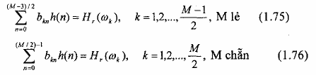
Then the linear equations (4.71) and (4.76) for the antisymmetric FIR filter become:
The frequency set given by equation (1.70) can also be used in equation (1.73) and equation (1.74) instead of using the frequency set given by equation (1.61).
Example 1.7:
Determine the impulse response h(n) of a linear phase FIR filter, with length M = 4.
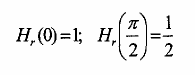
Frequency response H( ) at = 0 and =
is defined as follows:
2
Prize:
This is a fairly simple filter circuit design problem, the unknown parameters are h(0) and
h(1). The set of linear equations is:
a 00 h(0) + a 01 h(1) = H r (0) = 1
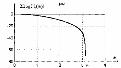
Figure 1.20 . Amplitude response characteristics of the linear phase FIR filter in Example 5.7
Example 1.8:
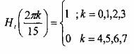
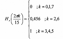
Determine the coefficients of a linear phase FIR filter with length M = 11, symmetric impulse response and frequency response satisfying the condition:
Prize:
This is a rather long filter circuit, more than could be found without the help of
Computers in solving systems of linear equations. Programming a computer to solve this system of equations, we can obtain the following solutions:
h(0) = h(14) = 0.04 981188 h(1) = h(13) = 0.04120224 h(2) = h(12) = 0.06666674 h(3) = h(11) = - 0.03648787 h(4) = h(10) = - 0.1078689 h(1) = h(9) = 0.03407801 h(6) = h(8) = 0.3188924 h(7) = 0.4666666
The frequency response of the filter is shown in Figure 1.21. We can see that this filter has an overshoot at the passband edge ahead of the transient. It also has fairly large sidelobes in the stopband, the largest sidelobe being -11 dB.
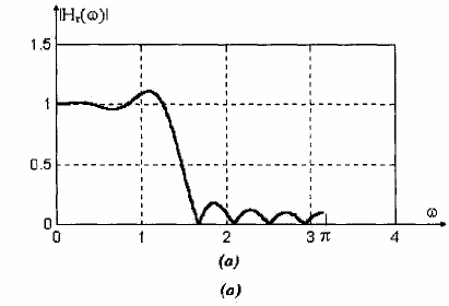
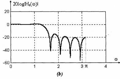
Figure 1.21: Amplitude response characteristics of a linear phase FIR filter of length M = 15. in example 5.8
Comment:
In the above example, we have illustrated the problem of designing a linear phase FIR filter with a frequency response that changes abruptly from the passband (H r ( r ) = 1) to the stopband, in which the stopband H r ( ) is defined as zero at discrete frequencies. We see that the filter has quite large sidebands, which is undesirable.
In the following example, instead of an abrupt change, we specify an intermediate value of H r ( ) in the transient band. The frequency response will have much smaller sidebands in the stopband.
Example 1.9:
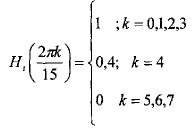
Repeat the design problem in Example 4.11 with the frequency response specifications.
To be:
Prize:
In this case, the filter coefficients are obtained from solving the equations
Linear is:
h(0) = h(14) = - 0.01412893 h(1) = h(13) = - 0.001941309 h(2) = h(12) = 0.04000004 h(3) = h(11) = 0.01223414 h(4) = h(10) = - 0.09138802 h(1) = h(9) = - 0.01808986 h(6) = h(8) = 0.3133176 h(7) = 0.12
Comment:
The resulting filter has the frequency response plotted in Figure 1.22. We see that the sidebands are now lower than in the previous example, the largest sideband being -41 dB.
In this example, we have widened the transient band which is a disadvantage, but we have gained a greater benefit, which is that we have reduced the sidebands significantly. So there are two opposite effects, if we add more frequency response parameters in the transient band the amplitude of the sidebands will decrease, while the width of the transient band will increase. Of course, we need to consider this carefully.
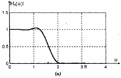
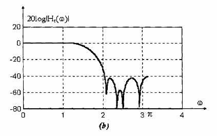
Figure 1.22. Amplitude response characteristics of a linear phase FIR filter of length M = 15, in example 5.9.
Example 1.10:
Determine the coefficients of the linear phase FIR filter circuit M = 16 whose impulse response is symmetrical and whose frequency response satisfies the condition;
Prize:
Solving the system of linear equations, we obtain the impulse response h(n): h(0) = h(11) = 0.01011716 h(1) = h(14) = 0.02774791
h(2) = h(13) = 0.04067173 h(3) = h(12) = - 0.02017317 h(4) = h(11) = 0.04840164 h(1) = h(10) = - 0.111712 h(6) = h(9) = - 0.266221 h(7) = h(8) = 0.3362424
This is a bandpass filter circuit, whose frequency response is plotted in Figure 4.23 with the largest sideband.
in the stop band down to -34dB.
Finally, the selection of frequencies k to determine the criteria of the filter's impulse response should be based on the cutoff frequency or passband edge frequency p and the stopband edge s . We can choose the length M of the filter so that in the frequencies { r } there are frequencies that coincide or nearly coincide with p , s .
The designer can also choose an arbitrary set of frequencies { r } that do not need to be evenly spaced, so that
for it to best fit the given response criteria.
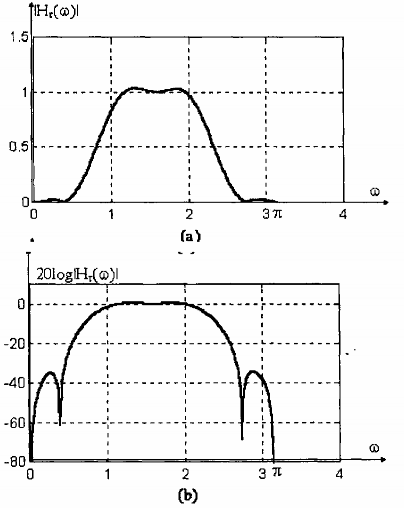
Figure 1.23: Amplitude response characteristics of a large linear phase FIR amplifier of length M = 16, in example 5.10.
1.2.2.4. Formula for calculating h(n)
- Our goal is to find the impulse response h(n) of the filter with the desired frequency response, thereby determining the transfer function (or difference equation) and constructing the structure of the filter. In section 1.2.2.3. we calculated h by solving the linear equations (1.70), (1.71) or (1.75), (176), more generally the matrix equation (1.77). Accordingly, we must determine the coefficient matrix akn (matrix [A]) or the coefficient matrix bkn (matrix [B]), and then, to solve the matrix equation (1.77) (in the case of choosing the antisymmetric impulse response, we replace matrix [A] with matrix [B]), we must calculate the inverse matrix. This is obviously time-consuming and laborious. Therefore, we want to establish a formula so that h(n) can be calculated directly).
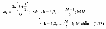
First, we determine the desired frequency response at a set of evenly spaced discrete frequencies {wk}:
k = 2
M
(k + ) with = 0 or = -
1(1.7 8)
2
And k = 0, 1, 2
M 1 when M is odd, k = 0, 1, 2,... M when M is even.
2 2
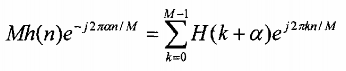
Then find the impulse response h(n) of the FIR filter from the selected frequency domain samples. By definition, the frequency response of an FIR filter of length M is:
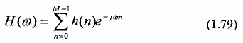
The value of the frequency response at frequencies { r } is:
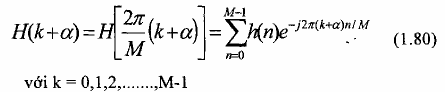
Since H(k+ ) is symmetric, the assigned frequencies can be reduced to
M 1
2
if M is odd,
M if M is even. However, here we want to examine the frequency characteristics at M points
2
as specified in pt(1.80).
To determine h(n) from H(k+ ), we multiply both sides of equation (1.80) by
e j2π2 m , where m
M
= 0, 1,. .., M-1, then take the sum over k = 0, 1,. .. , M- 1. The right side of equation (1.77) will reduce to Mh(n)
ej2π2 m
M
and we get:
We see that in the case = 0 then H(k) = DFT[h(n)] and h(n) = IDFT[H(k)].
To find the formula for h(n), we will rely on the symmetry of and the value of a.
We divide into specific cases as follows:
- = 0, more symmetrical.
- = 1/2, more symmetrical.
- = 0, h(n) is antisymmetric.
- = 1/2, h(n) is antisymmetric.
It should also be noted that, under the symmetric and antisymmetric conditions considered, h(n) is always real-valued.
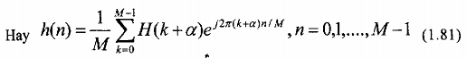
Consider the case = 0, more symmetric: h(n) = h (M-1-n)
Since h(n) is real, from equation (1.77) we can easily deduce that H(k) = H*(Mk), and because it is more symmetric, from equation (1.77) we get: (1.82)
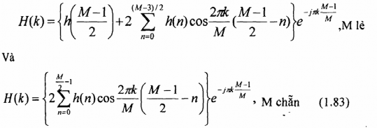
We see that the terms in the brackets { } are the samples of H r ( ) at the frequencies
k =2 k/M. Therefore, the expression of Chemistry has the form:
For convenience, we rewrite:
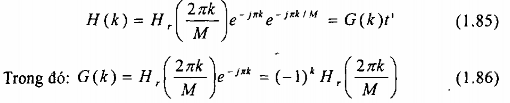
Since H r (2 k/M) is real-valued, G(k) is also a real sequence. Furthermore, from the condition H(k)
= H*(Mk) leads to the result:
G(k) = - G(Mk) (1.87)
When M is even, then equation (1.84) requires that: G(M/2) = 0, otherwise the sample of the frequency response at = must be 0.
From the symmetry of the real-valued frequency samples G(k) in equation (1.84), we can establish the formula for calculating the impulse response h(n) of the FIR filter.
We start from equation (1.81) with = 0