x1
COM
+
x1
COM
Maybe you are interested!
-

 Car body electrical practice - 8
zt2i3t4l5ee
zt2a3gs
zt2a3ge
zc2o3n4t5e6n7ts
If the voltage is out of specification, replace the wire or connector.
If the voltage is within specification, install the front fog light relay and follow step 5.
Step 5 Check the front fog light switch
- Remove the D4 connector of the fog light switch
- Use a multimeter to measure the resistance of the front fog light switch.
Measurement location
Condition
Standard
D4-3 (BFG) -D4-4 (LFG)
Light switchFront Fog OFF
>10kΩ
D4-3 (BFG) -D4-4 (LFG)
Front fog light switchON
<1 Ω
- Standard resistor
D4 connector is located on the combination switch assembly.
If the resistance is out of specification, replace the combination switch (the fog light switch is located in the combination switch).
If the resistance is within specification, follow step 6.
Step 6 Check wiring and connectors (front fog light relay-light selector switch)
- Disconnect connector D4 of the combination switch assembly
- Use a voltmeter to measure the voltage value of jack D4 on the wire side.
Measurement location
Control modecontrol
Standard
D4-3 (BFG) - (-) AQ
TAIL
11 to 14 V
D4 connector for the wiring of the combination switch assembly
If the voltage does not meet the standard, replace the wire or connector.
If the voltage is within standard, there may have been an error in the previous measurements.
Step 7 Check the front fog lights
- Remove the front fog light electrical connector.
- Supply battery voltage to the fog lamp terminals
Jack 8, B9 of front fog lamp on the electrical side
blind first.
Power supply location
Terms and Conditions
Battery positive terminal - Terminal 2Battery negative terminal - Terminal 1
Fog lightsbefore morning
- If the light does not come on, replace the bulb.
If the light is on, re-plug the jack and continue to step 8.
Step 8 Check wiring and connectors (relay and front fog lights)
- Disconnect the B8 and B9 connectors of the front fog lights.
- Use a voltmeter to measure voltage at the following locations:
Measurement location
Switch location
Terms and Conditions
B8-2 - (-) AQ
Electric lock ON TAIL size switchFog switch ON
11 to 14 V
B9-2 - (-) AQ
Electric lock ONTAIL size switch Fog switch ON
11 to 14 V
B8 and B9 connectors on the front fog lamp wiring side
Voltage is not up to standard, repair or replace the jack. If up to standard, there may have been an error in the measurement process.
2.2.4. Procedure for removing, installing and adjusting fog lights 1. Procedure for removing
- Remove the front inner ear pads
Use a screwdriver to remove the 3 screws and remove the front part of the front inner ear liner
-Remove the fog light assembly
+ Disconnect the connector.
+ Use a screwdriver to remove 3 screws to remove the fog light cover
2. Installation sequence
-Rotate the fog lamp bulb in the direction indicated by the arrow as shown in the figure and remove the fog lamp from the fog lamp assembly.
-Rotate the fog light bulb in the direction indicated by the arrow as shown in the figure and install the light into the fog light assembly.
- Use a screwdriver to install the fog light cover
-Install the electrical connector
Attention: Be careful not to damage the plastic thread on the lamp assembly.
- Install the front inner ear pads
Use a screwdriver to install the front inner bumper with 3 screws.
3. Prepare the vehicle to adjust the fog light convergence. Prepare the vehicle:
- Make sure there is no damage or deformation to the vehicle body around the fog lights.
- Add fuel to the fuel tank
- Add oil to standard level.
- Add engine coolant to standard level.
- Inflate the tire to standard pressure.
- Place spare tire, tools and jack in original design position
- Do not leave any load in the luggage compartment.
- Let a person weighing about 75 kg sit in the driver's seat.
4. Prepare to check the fog light convergence
a/ Prepare the vehicle status as follows:
- Place the car in a dark enough place to see the lines. The lines are the dividing line, below which the light from the fog lights can be seen but above which it cannot.
- Place the car perpendicular to the wall.
- Keep a distance of 7.62 m between the center of the fog lamp and the wall.
- Park the car on level ground.
- Press the car down a few times to stabilize the suspension.
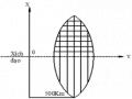
Note: A distance of approximately 7.62 m is required between the vehicle (fog lamp center) and the wall to adjust the convergence correctly. If the distance of 7.62 m cannot be achieved, set the correct distance of 3 m to check and adjust the fog lamp convergence. (Since the target area varies with the distance, please follow the instructions as shown in the figure.)
b/ Prepare a piece of thick white paper about 2 m high and 4 m wide to use as a screen.
c/ Draw a vertical line through the center of the screen (line V).
d/ Set the screen as shown in the picture. Note:
- Keep the screen perpendicular to the ground.
- Align the V line on the screen with the center of the vehicle.
e/Draw the reference lines (H, V LH and V RH lines) on the screen as shown in the figure.HINT:
Mark the center of the fog lamp on the screen. If the center mark cannot be seen on the fog lamp, use the center of the fog lamp or the manufacturer's name mark on the fog lamp as the center mark.
H line (fog light height):
Draw a line across the screen so that it passes through the center mark. Line H should be at the same height as the center mark of the fog light bulb.
Line V LH, V RH (center mark position of left fog lamp LH and right fog lamp RH):
Draw two lines so that they intersect line H at the center marks.
5. Check the fog light convergence
a/ Cover the fog lamp or remove the connector of the other side fog lamp to prevent light from the unchecked fog lamp from affecting the fog lamp convergence test.
b/ Start the engine.
c/ Turn on the fog lights and make sure that the dividing line is outside the standard area as shown in the drawing.
6. Adjust the fog light convergence
Use a screwdriver to adjust the fog light to the standard area by turning the toe adjustment screw.
Note: If the screw is adjusted too far, loosen it and then tighten it again, so that the last rotation of the light adjustment screw is clockwise.
3. Self-study questions
1. Describe the operating principle of the lighting system with automatic headlight function
2. Describe the operating principle of the lighting system with the function of rotating headlights when turning
3. Draw diagram and connect lighting system on Hyundai Porter car
4. Draw diagram and connect lighting system on Honda Accord 1992
5. Draw the lighting circuit on a 1993 Toyota Lexus
LESSON 3 MAINTENANCE AND REPAIR OF SIGNAL SYSTEM
I. IMPLEMENTATION GOAL
After completing this lesson, students will be able to:
- Distinguish between types of signals on cars
- Correctly describe common symptoms and suspected areas causing damage.
- Connecting signal circuits ensures technical requirements
- Disassemble, install, check, maintain and repair the signal system to ensure technical requirements.
- Ensure safety in work and industrial hygiene
II. LESSON CONTENT
1. General description
The signal system equipped on cars aims to create signals to notify other vehicles participating in traffic about the vehicle's operating status such as: stopping, parking, braking, reversing, turning...
Signals are used either by light such as headlamps, brake lights, turn signals….. or by sound such as horns, reverse music….
Just like the lighting system. A signal system circuit usually consists of: battery, fuse, wire, relay, electrical load and control switch. Only some switches of the signal system are on the combination switch. The switches of other signals are usually located in different locations such as in the gearbox or brake pedal……
2. Maintenance and repair
2.1. Turn signals and hazard lights
The installation location of the turn signal is shown in Figure 3.1. The turn signal control switch is located in the combination switch under the steering wheel. Turning this switch to the right or left will make the turn signal turn right or left.
The hazard light switch is used when the vehicle has a problem while participating in traffic. When the hazard light switch is turned on, all the turn signals on the vehicle will light up at a certain frequency. The hazard light switch is usually placed separately from the turn signal switch (some old cars integrate the hazard and turn signal switches on the same combination switch cluster).
Figure 3.1 Turn signal switch Figure 3.2 Hazard switch
The part that generates the flashing frequency for the lights is called a turn signal relay. The turn signal relay usually has 3 terminals: B (positive power supply); E (negative power supply); L (providing the turn signal switch to distribute to the
lamp)
2.1.1. Circuit diagram
To generate the frequency for the turn signal, a turn signal relay is used in the turn signal circuit. The current from the turn signal relay will be sent to the turn signal switch assembly to distribute the current to the turn signal lights for the driver's purpose.
Figure 3.3. Schematic diagram of a turn signal circuit without a hazard switch
1. Battery; 2. Electric lock; 3. Turn signal relay; 4. Turn signal switch; 5. Turn signal lamp; 6. Turn signal lamp; 7. Hazard switch
Figure 3.4 Schematic diagram of turn signal circuit with hazard switch
1. Battery; 2. Combination switch cluster; 3. Turn signal;
4. Turn signal light; 5. Turn signal relay
Today's cars no longer use three-pin turn signal relays (B, L, E) but use eight-pin turn signal relays (figure 3.5) (pin number 8 is used for hazard lights).
For this type, the current supplying the turn signal lights is supplied directly from the turn signal relay to the lights.
div.maincontent .p { color: black; font-family:"Times New Roman", serif; font-style: normal; font-weight: normal; text-decoration: none; font-size: 14pt; margin:0pt; } div.maincontent p { color: black; font-family:"Times New Roman", serif; font-style: normal; font-weight: normal; text-decoration: none; font-size: 14pt; margin:0pt; } div.maincontent .s1 { color: black; font-family:"Times New Roman", serif; font-style: normal; font-weight: normal; text-decoration: none; font-size: 13pt; } div.maincontent .s2 { color: black; font-family:"Times New Roman", serif; font-style: italic; font-weight: normal; text-decoration: none; font-size: 14pt; } div.maincontent .s3 { color: black; font-family:"Times New Roman", serif; font-style: normal; font-weight: normal; text-decoration: none; font-size: 14pt; } div.maincontent .s4 { color: black; font-family:"Times New Roman", serif; font-style: normal; font-weight: normal; text-decoration: none; font-size: 13pt; } div.maincontent .s5 { color: black; font-family:"Times New Roman", serif; font-style: normal; font-weight: normal; text-decoration: none; font-size: 13pt; vertical-align: 1pt; } div.maincontent .s6 { color: black; font-family:"Times New Roman", serif; font-style: normal; font-weight: normal; text-decoration: none; font-size: 11pt; } div.maincontent .s7 { color: black; font-family:"Times New Roman", serif; font-style: normal; font-weight: normal; text-decoration: none; font-size: 14pt; vertical-align: -9pt; } div.maincontent .s8 { color: black; font-family:"Times New Roman", serif; font-style: normal; font-weight: normal; text-decoration: none; font-size: 11pt; } div.maincontent .s9 { color: #008000; font-family:"Times New Roman", serif; font-style: normal; font-weight: normal; text-decoration: none; font-size: 14pt; } div.maincontent .s10 { color: black; font-family:"Times New Roman", serif; font-style: italic; font-weight: normal; te
Car body electrical practice - 8
zt2i3t4l5ee
zt2a3gs
zt2a3ge
zc2o3n4t5e6n7ts
If the voltage is out of specification, replace the wire or connector.
If the voltage is within specification, install the front fog light relay and follow step 5.
Step 5 Check the front fog light switch
- Remove the D4 connector of the fog light switch
- Use a multimeter to measure the resistance of the front fog light switch.
Measurement location
Condition
Standard
D4-3 (BFG) -D4-4 (LFG)
Light switchFront Fog OFF
>10kΩ
D4-3 (BFG) -D4-4 (LFG)
Front fog light switchON
<1 Ω
- Standard resistor
D4 connector is located on the combination switch assembly.
If the resistance is out of specification, replace the combination switch (the fog light switch is located in the combination switch).
If the resistance is within specification, follow step 6.
Step 6 Check wiring and connectors (front fog light relay-light selector switch)
- Disconnect connector D4 of the combination switch assembly
- Use a voltmeter to measure the voltage value of jack D4 on the wire side.
Measurement location
Control modecontrol
Standard
D4-3 (BFG) - (-) AQ
TAIL
11 to 14 V
D4 connector for the wiring of the combination switch assembly
If the voltage does not meet the standard, replace the wire or connector.
If the voltage is within standard, there may have been an error in the previous measurements.
Step 7 Check the front fog lights
- Remove the front fog light electrical connector.
- Supply battery voltage to the fog lamp terminals
Jack 8, B9 of front fog lamp on the electrical side
blind first.
Power supply location
Terms and Conditions
Battery positive terminal - Terminal 2Battery negative terminal - Terminal 1
Fog lightsbefore morning
- If the light does not come on, replace the bulb.
If the light is on, re-plug the jack and continue to step 8.
Step 8 Check wiring and connectors (relay and front fog lights)
- Disconnect the B8 and B9 connectors of the front fog lights.
- Use a voltmeter to measure voltage at the following locations:
Measurement location
Switch location
Terms and Conditions
B8-2 - (-) AQ
Electric lock ON TAIL size switchFog switch ON
11 to 14 V
B9-2 - (-) AQ
Electric lock ONTAIL size switch Fog switch ON
11 to 14 V
B8 and B9 connectors on the front fog lamp wiring side
Voltage is not up to standard, repair or replace the jack. If up to standard, there may have been an error in the measurement process.
2.2.4. Procedure for removing, installing and adjusting fog lights 1. Procedure for removing
- Remove the front inner ear pads
Use a screwdriver to remove the 3 screws and remove the front part of the front inner ear liner
-Remove the fog light assembly
+ Disconnect the connector.
+ Use a screwdriver to remove 3 screws to remove the fog light cover
2. Installation sequence
-Rotate the fog lamp bulb in the direction indicated by the arrow as shown in the figure and remove the fog lamp from the fog lamp assembly.
-Rotate the fog light bulb in the direction indicated by the arrow as shown in the figure and install the light into the fog light assembly.
- Use a screwdriver to install the fog light cover
-Install the electrical connector
Attention: Be careful not to damage the plastic thread on the lamp assembly.
- Install the front inner ear pads
Use a screwdriver to install the front inner bumper with 3 screws.
3. Prepare the vehicle to adjust the fog light convergence. Prepare the vehicle:
- Make sure there is no damage or deformation to the vehicle body around the fog lights.
- Add fuel to the fuel tank
- Add oil to standard level.
- Add engine coolant to standard level.
- Inflate the tire to standard pressure.
- Place spare tire, tools and jack in original design position
- Do not leave any load in the luggage compartment.
- Let a person weighing about 75 kg sit in the driver's seat.
4. Prepare to check the fog light convergence
a/ Prepare the vehicle status as follows:
- Place the car in a dark enough place to see the lines. The lines are the dividing line, below which the light from the fog lights can be seen but above which it cannot.
- Place the car perpendicular to the wall.
- Keep a distance of 7.62 m between the center of the fog lamp and the wall.
- Park the car on level ground.
- Press the car down a few times to stabilize the suspension.
Note: A distance of approximately 7.62 m is required between the vehicle (fog lamp center) and the wall to adjust the convergence correctly. If the distance of 7.62 m cannot be achieved, set the correct distance of 3 m to check and adjust the fog lamp convergence. (Since the target area varies with the distance, please follow the instructions as shown in the figure.)
b/ Prepare a piece of thick white paper about 2 m high and 4 m wide to use as a screen.
c/ Draw a vertical line through the center of the screen (line V).
d/ Set the screen as shown in the picture. Note:
- Keep the screen perpendicular to the ground.
- Align the V line on the screen with the center of the vehicle.
e/Draw the reference lines (H, V LH and V RH lines) on the screen as shown in the figure.HINT:
Mark the center of the fog lamp on the screen. If the center mark cannot be seen on the fog lamp, use the center of the fog lamp or the manufacturer's name mark on the fog lamp as the center mark.
H line (fog light height):
Draw a line across the screen so that it passes through the center mark. Line H should be at the same height as the center mark of the fog light bulb.
Line V LH, V RH (center mark position of left fog lamp LH and right fog lamp RH):
Draw two lines so that they intersect line H at the center marks.
5. Check the fog light convergence
a/ Cover the fog lamp or remove the connector of the other side fog lamp to prevent light from the unchecked fog lamp from affecting the fog lamp convergence test.
b/ Start the engine.
c/ Turn on the fog lights and make sure that the dividing line is outside the standard area as shown in the drawing.
6. Adjust the fog light convergence
Use a screwdriver to adjust the fog light to the standard area by turning the toe adjustment screw.
Note: If the screw is adjusted too far, loosen it and then tighten it again, so that the last rotation of the light adjustment screw is clockwise.
3. Self-study questions
1. Describe the operating principle of the lighting system with automatic headlight function
2. Describe the operating principle of the lighting system with the function of rotating headlights when turning
3. Draw diagram and connect lighting system on Hyundai Porter car
4. Draw diagram and connect lighting system on Honda Accord 1992
5. Draw the lighting circuit on a 1993 Toyota Lexus
LESSON 3 MAINTENANCE AND REPAIR OF SIGNAL SYSTEM
I. IMPLEMENTATION GOAL
After completing this lesson, students will be able to:
- Distinguish between types of signals on cars
- Correctly describe common symptoms and suspected areas causing damage.
- Connecting signal circuits ensures technical requirements
- Disassemble, install, check, maintain and repair the signal system to ensure technical requirements.
- Ensure safety in work and industrial hygiene
II. LESSON CONTENT
1. General description
The signal system equipped on cars aims to create signals to notify other vehicles participating in traffic about the vehicle's operating status such as: stopping, parking, braking, reversing, turning...
Signals are used either by light such as headlamps, brake lights, turn signals….. or by sound such as horns, reverse music….
Just like the lighting system. A signal system circuit usually consists of: battery, fuse, wire, relay, electrical load and control switch. Only some switches of the signal system are on the combination switch. The switches of other signals are usually located in different locations such as in the gearbox or brake pedal……
2. Maintenance and repair
2.1. Turn signals and hazard lights
The installation location of the turn signal is shown in Figure 3.1. The turn signal control switch is located in the combination switch under the steering wheel. Turning this switch to the right or left will make the turn signal turn right or left.
The hazard light switch is used when the vehicle has a problem while participating in traffic. When the hazard light switch is turned on, all the turn signals on the vehicle will light up at a certain frequency. The hazard light switch is usually placed separately from the turn signal switch (some old cars integrate the hazard and turn signal switches on the same combination switch cluster).
Figure 3.1 Turn signal switch Figure 3.2 Hazard switch
The part that generates the flashing frequency for the lights is called a turn signal relay. The turn signal relay usually has 3 terminals: B (positive power supply); E (negative power supply); L (providing the turn signal switch to distribute to the
lamp)
2.1.1. Circuit diagram
To generate the frequency for the turn signal, a turn signal relay is used in the turn signal circuit. The current from the turn signal relay will be sent to the turn signal switch assembly to distribute the current to the turn signal lights for the driver's purpose.
Figure 3.3. Schematic diagram of a turn signal circuit without a hazard switch
1. Battery; 2. Electric lock; 3. Turn signal relay; 4. Turn signal switch; 5. Turn signal lamp; 6. Turn signal lamp; 7. Hazard switch
Figure 3.4 Schematic diagram of turn signal circuit with hazard switch
1. Battery; 2. Combination switch cluster; 3. Turn signal;
4. Turn signal light; 5. Turn signal relay
Today's cars no longer use three-pin turn signal relays (B, L, E) but use eight-pin turn signal relays (figure 3.5) (pin number 8 is used for hazard lights).
For this type, the current supplying the turn signal lights is supplied directly from the turn signal relay to the lights.
div.maincontent .p { color: black; font-family:"Times New Roman", serif; font-style: normal; font-weight: normal; text-decoration: none; font-size: 14pt; margin:0pt; } div.maincontent p { color: black; font-family:"Times New Roman", serif; font-style: normal; font-weight: normal; text-decoration: none; font-size: 14pt; margin:0pt; } div.maincontent .s1 { color: black; font-family:"Times New Roman", serif; font-style: normal; font-weight: normal; text-decoration: none; font-size: 13pt; } div.maincontent .s2 { color: black; font-family:"Times New Roman", serif; font-style: italic; font-weight: normal; text-decoration: none; font-size: 14pt; } div.maincontent .s3 { color: black; font-family:"Times New Roman", serif; font-style: normal; font-weight: normal; text-decoration: none; font-size: 14pt; } div.maincontent .s4 { color: black; font-family:"Times New Roman", serif; font-style: normal; font-weight: normal; text-decoration: none; font-size: 13pt; } div.maincontent .s5 { color: black; font-family:"Times New Roman", serif; font-style: normal; font-weight: normal; text-decoration: none; font-size: 13pt; vertical-align: 1pt; } div.maincontent .s6 { color: black; font-family:"Times New Roman", serif; font-style: normal; font-weight: normal; text-decoration: none; font-size: 11pt; } div.maincontent .s7 { color: black; font-family:"Times New Roman", serif; font-style: normal; font-weight: normal; text-decoration: none; font-size: 14pt; vertical-align: -9pt; } div.maincontent .s8 { color: black; font-family:"Times New Roman", serif; font-style: normal; font-weight: normal; text-decoration: none; font-size: 11pt; } div.maincontent .s9 { color: #008000; font-family:"Times New Roman", serif; font-style: normal; font-weight: normal; text-decoration: none; font-size: 14pt; } div.maincontent .s10 { color: black; font-family:"Times New Roman", serif; font-style: italic; font-weight: normal; te -
 Electronic Measurement Industrial Electronics - College - Dong Thap Vocational College - 10
 -
 Electronic Measurement Industrial Electronics - College - Dong Thap Vocational College - 7
 -
 Application of information technology and electronic total station in establishing cadastral map of map sheet No. 16 from measurement data in Quynh Lap commune, Hoang Mai town, Nghe An province - 2
 -
 Measure 4: Make Tools and Toys to Use in Children's Play Activities
+
- If the needle does not rise after 2 measurements: the diode is broken.
- If the needle reads 0 twice : the diode is shorted.
- If the two readings have almost the same value: the diode is leaking.
* Zener diode:
Measures like a rectifier diode.
* LED measurement:
x1
COM
+
A
K
Like testing a rectifier diode, if:
- Two reversible measurements LED does not light up: LED is broken.
- If the LED is on, it means the LED is forward biased. The leg connected to the black stick is the Anode, the leg connected to the red stick is the Cathode.
C828
BCE
C1061
BCE
b) Measure BT:
A
BEIGE
EBC
C
BEIGE
EBC
Symbols on circuit diagram
* Equivalent diagram of transistor:
C
B
NP-
E
C
B
PNP
E
- Turn the meter to the Rx10 scale.
- Determine pin B: we measure the pins in turn until there is a fixed stick on 1 pin, the remaining stick touches the remaining 2 pins, the needle goes up, which pin the fixed stick touches, that pin is pin B. When we know pin B, we look at the color of the stick touching pin B, if the stick is black then the transistor is NPN type, if the stick is red then the transistor is PNP type.
- Determine pins C, E: When you know pin B, put 2 measuring sticks into the 2 remaining pins, short-circuit pin B with the pin where the needle is close to or more than half way up, that pin is pin C. The black stick is connected to pin C if it is NPN and the red stick is connected to pin C if it is PNP)
C
x1
COM
+
B
E
C
x1
B
COM
+
E
- When inserting 2 measuring rods into 2 legs C, E, move the 2 rods back and forth, if:
+ Needle does not rise: Transistor is good.
+ Needle up: transistor is punctured.
c) FET measurement:
FET measurement is more complicated than BT, we need to pay attention to the following points:
- The component to be tested is FET or MOSFET.
- FET is N or P channel type.
- If it is MOSFET, see if it is continuous or discrete MOSFET.
We should pay attention to limit removing FET from the circuit when we are not sure what it is.
FET or MOSFET, determining the type of FET is very necessary because MOSFET is very sensitive to static electricity, so when in contact with MOSFET, we take some anti-static measures by:
+ Use a metal short circuit ring worn on the hand.
+ Ground the soldering iron tip used to remove and attach components.
+ Never remove or attach components while the circuit is still powered.
electricity.
* Measure to determine FET pins and type:
- Turn the scale Rx1K.
- Determine the G leg: we measure the legs in turn until there is a fixed stick on 1 leg, the remaining stick touches the remaining 2 legs, the needle goes up, which leg the fixed stick touches, that leg is the G leg. When we know the G leg, we look at the color of the stick touching the G leg, if the stick is black then the FET is an N channel, if the stick is red then the FET is a P channel.
- Measure the resistance value of the D, S pin pair. Several hundred several tens of K
COM
+
D
COM
+
D
G
Several hundred
several dozen
G
S
N-channel JFET
Several hundred
several tens of K
P S channel JFET
- Determine the D, S pins of N channel type: When you know the G pin, put the black stick on the D pin, the red stick on the S pin, use your hand to press the G pin. If the needle goes up and then holds it and the next time the needle returns, then the FET is good.
D
G
COM +
S
- Determine the D, S pins of P channel type: When you know the G pin, put the red stick on the D pin, the black stick on the S pin, use your hand to press the G pin, if the needle goes up and then holds itself, then the FET is good.
D
COM
+
G
S
* MOSFET testing:
D
COM
+
G
S
D
COM
+
G
S
N-channel MOSFET P-channel MOSFET
- Turn the scale Rx10K.
- Measure twice (change the measuring stick) at the G - S and G - D legs. If the needle does not rise, it is good.
If the needle goes up, the MOSFET is leaking or shorted.
- Note: between the D and S poles of the power MOSFET there is usually a buffer diode, so Rx1 has an upward direction, the polarity of the diode depends on whether the MOSFET is N-channel or P-channel.
- MOSFET test:
+ To check MOSFET, turn the Rx10K scale, depending on the MOSFET channel, place the appropriate measuring probe. For example, for N-channel MOSFET, place the black probe on pole D, the red probe on pole S, and vice versa for P-channel MOSFET.
D
G
COM
+
S
+ Use your finger to press, the needle jumps to position 0 tens of K ), good MOSFET.
* Note: To determine the G, D, S pins and the structure of the MOSFET accurately, look it up in books or online.
* Universal DVOM
1.3.1 – Measure DC or AC voltage)
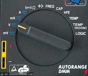
Set the meter to DC or AC voltage scale
- Put the red meter probe into the VΩ mA jack and the black probe into the COM jack.
- Press the DC/AC button to select the measuring scale as DC if measuring DC voltage or AC if measuring AC voltage.
- Turn the switch to position V, set the highest scale if the voltage is not known, if the value is in decimal form, then reduce the scale later.
- Place the scale on the voltage to be measured and read the value on the LCD screen of the meter.
- If the measuring rod is placed upside down with the DC current, the meter will display a negative value.
1.3.2 Measure DC current (AC)
- Switch the red meter stick to mA scale if measuring small current, or 20A if measuring large current.
- Turn the switch to position A
- Press the DC/AC button to select DC or AC current measurement.
- Place the measuring probe in series with the circuit to be measured.
- Read the value displayed on the screen.
1.3.3 Resistance measurement
- Return the plug position as when measuring voltage.
- Turn the switch to the Ω measurement position, if you don't know the resistance value, choose the highest measurement scale, if the result is a decimal, reduce it.
- Place the measuring probes on both ends of the resistor.
- Read the value on the display.
- The resistance measurement function can also measure continuity. Suppose you measure a wire segment with a resistance scale. If there is continuity, the meter will make a beeping sound.
1.3.4 Frequency measurement
- Turn the switch to the FREQ or Hz position
- Set the scale as when measuring voltage.
- Place the measuring stick at the points to be measured.
- Read the value on the screen.
1.3.5 Logic Measurement
- Logic measurement is measuring into digital circuits) or measuring the command pins of the microprocessor, Logic measurement is essentially measuring the state of electricity - Symbol 1" or no electricity
0″, measurement as follows:
- Turn the switch to the LOGIC position
- Place the red stick in the position to be measured and the black stick on the ground.
- The display shows ▲ to indicate high logic level, and ▼ to indicate low logic level.
1.3.6 Measure other functions
Digital multimeters also have some other measuring functions such as Diode measurement, Capacitor measurement, Transistor measurement, but if we measure the above components, we should use a mechanical meter which will give better results and measure faster.
2.6 PRACTICE
2.6.1 Practice measuring resistance R)
I
A
IV
I x
U
V
R X
r v
- Circuit 1:
* Implementation process
Step 1: Prepare to select measuring tools, materials and equipment). Step 2: Assemble the circuit according to the diagram.
Step 3: Check for cold. Step 4: Power on.
Step 5: Check the safety of the connection points.
Step 6: Observe the measuring device. Read and record the results. Step 7: Apply the formula to calculate the resistance value.
-------------------------------------------------- -------------------------------------------------- ----
-------------------------------------------------- -------------------------------------------------- ----
-------------------------------------------------- -------------------------------------------------- ----
-------------------------------------------------- -------------------------------------------------- ----
-------------------------------------------------- -------------------------------------------------- ----
-------------------------------------------------- -------------------------------------------------- ----
-------------------------------------------------- -------------------------------------------------- ----
* Common errors, causes and remedies
-------------------------------------------------- -------------------------------------------------- ----
-------------------------------------------------- -------------------------------------------------- ----
-------------------------------------------------- -------------------------------------------------- ----
-------------------------------------------------- -------------------------------------------------- ----
-------------------------------------------------- -------------------------------------------------- ----
-------------------------------------------------- -------------------------------------------------- ----
-------------------------------------------------- -------------------------------------------------- ----
V
I
A
go out
U
- Circuit 2:
R X
* Implementation process
Step 1: Prepare to select measuring tools, materials and equipment). Step 2: Assemble the circuit according to the diagram.
Step 3: Check for cold. Step 4: Power on.
Step 5: Check the safety of the connection points.
Step 6: Observe the measuring device. Read and record the results. Step 7: Apply the formula to calculate the resistance value.
-------------------------------------------------- -------------------------------------------------- ----
-------------------------------------------------- -------------------------------------------------- ----
-------------------------------------------------- -------------------------------------------------- ----
-------------------------------------------------- -------------------------------------------------- ----
-------------------------------------------------- -------------------------------------------------- ----
-------------------------------------------------- -------------------------------------------------- ----
-------------------------------------------------- -------------------------------------------------- ----
* Based on the results of the comments on the two diagrams above.
-------------------------------------------------- -------------------------------------------------- ----
-------------------------------------------------- -------------------------------------------------- ----
-------------------------------------------------- -------------------------------------------------- ----
-------------------------------------------------- -------------------------------------------------- ----
-------------------------------------------------- -------------------------------------------------- ----
-------------------------------------------------- -------------------------------------------------- ----
-------------------------------------------------- -------------------------------------------------- ---
2.6.2 Measure DC voltage: knowing R = 1k

I
5V
+
-
V
R
* Implementation process
Step 1: Prepare to select measuring tools, materials and equipment).
Step 2: Assemble the circuit according to the diagram. Step 3: Check for cold.
Step 4: Power on.
Step 5: Check the safety of the connection points.
Step 6: Observe on the measuring device. Read and record the results.
-------------------------------------------------- -------------------------------------------------- ----
-------------------------------------------------- -------------------------------------------------- ----
-------------------------------------------------- -------------------------------------------------- ----
-------------------------------------------------- -------------------------------------------------- ----
-------------------------------------------------- -------------------------------------------------- ----
-------------------------------------------------- -------------------------------------------------- ----
-------------------------------------------------- -------------------------------------------------- ----
2.6.3 Measurement of alternating current (AC) voltage
- Measure single phase AC voltage

I
220VAC
V
100W
220V
* Implementation process
Step 1: Prepare to select measuring tools, materials and equipment). Step 2: Assemble the circuit according to the diagram.
Step 3: Check for cold. Step 4: Power on.
Step 5: Check the safety of the connection points.
Step 6: Observe on the measuring device. Read and record the results.
-------------------------------------------------- -------------------------------------------------- ----
-------------------------------------------------- -------------------------------------------------- ----
-------------------------------------------------- -------------------------------------------------- ----
-------------------------------------------------- -------------------------------------------------- ----
-------------------------------------------------- -------------------------------------------------- ----
----------------------------------------
- Measure 3-phase AC voltage