Tc is the wavelength of light in vacuum.
Equation (2.2) is obtained .
2.1.4. Light intensity
call
is the wave function of light.
Maybe you are interested!
-

 Forestry Extension Model Figure 4.12. Mass Model
 -
 Diffraction of Light. Huygens-Fresnel Principle
 -
 Historical Figure Doctor Dang Thuy Tram and Her Two Diaries
 -
 Unit Root Test Results of Figure 1
 -
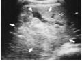 Subcapsular Liver Hematoma in the Shape of a Crescent (Long Arrow) or Lens and Intraparenchymal Hematomas (Short Arrow).
Luminous intensity characterizes the brightness at each point in space through which light waves pass.
Definition :
Ear light intensity
one point is belt
thank you
g has value equal to energy
average of light waves passing through a unit area placed perpendicular to the light path in a unit time .
Since the energy density of an electromagnetic wave is directly proportional to the square of the boundary
The magnitude of the electric field intensity vector should be equal to the square of the amplitude of the light oscillation at that point:
I kA 2
a point proportional to
with k being the proportional coefficient .
When studying the phenomena of gratitude
g interference, much
characteristic distance for the character
In the wave nature of light, people only need to compare the luminous intensity at different points without needing to calculate the specific value of the luminous intensity , so we can assume k = 1 :
I A 2 (2.3)
2.1.5. Principle of superposition of waves
When two or more light waves intersect at a point
somewhere in space, the synthesis of superposition of waves. This principle is
The waves obey the following principle :
When two or more light waves meet, they separate into separate waves.
not affected by other waves
loan
. After meeting, the light waves
bright cloud
transmitted as is , and ear
as the meeting point oscillates with light
sum of component light fluctuations .
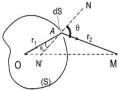
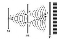
2.1.6. Huygens' principle
Lip
point in space received
light waves from real light source
S is transmitted evenly.
become a secondary light source emitting light waves in front of it
Huygens' principle is shown in Figure 2.7.
rough description
2.2. LIGHT INTERFERENCE
2.2.1 . Definition
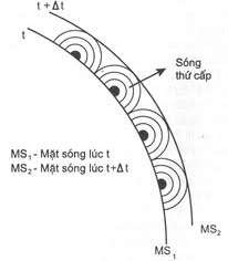
Figure 2.7
Thank you now
g light interference is a phenomenon
meeting of two or
multiple light waves combined
, the result is that in the interference field will appear
like alternating bright and dark fringes .
Interference conditions :
Thank you now
g Interference occurs only for coherent light waves .
. Light waves
light combination
are waves whose phase difference does not change over time .
My principles
output two combined light waves
is from a single wave
split into two separate waves. A device for producing combined light waves.
combinations: for example Young's slit, Fresnel mirror, Bile bilens...
2.2.2 . Current survey
Figure 2.8. Young interference.
g interference
a. Extreme conditions
big, big
sub-interference
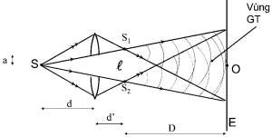
Figure 2.9. Fresnel mirror Figure 2.10. Bile bilens
Consider two monochromatic light sources, their luminosity at positions S 1 and S 2 is :
x ( S 1 ) A 1 cos tx ( S 2 ) A 2 cos t
S 1 and S 2 . Knife equation
At M we get
two light oscillations:
x ( M ) A cos( t 2 L 1 )
1 1
x 2 ( M ) A 2
cos( t 2 L 2 )
with L 1 and L 2 being the light paths corresponding to the segment
line d 1 S 1 M , d 2 S 2 M .
Because the distance S1 S2 is much smaller than the distance from the plane of the two slits to the observation screen , we consider this as a combination of two oscillations of the same direction and frequency .
The total light oscillation at M is:
x ( M ) x 1 ( M ) x 2 ( M ) A cos( t )
in which: A, follow the oscillation synthesis formula, according to which:
A A 2 A A cos
2 2
1 2
1 2
A
with:
(2.4)
2 ( L L ) (2.5)
2 1 1 2
Thus the amplitude of the light oscillation is the sum of the two oscillations.
ears
M depends on phase difference
If two oscillations are in phase, the phase difference 2k , then the amplitude of oscillation
general morning
ears
M will have a maximum value: A A 1 A 2 and the intensity of the light
point M is pole
great. Thus the extreme condition
band
interference is:
2 ( L L ) 2k
1 2
L 1 L 2 k with k = 0, ± 1 , ± 2... ( 2.6 )
If two oscillations are out of phase, the phase difference (2k 1 ) , then the amplitude of the knife
total luminosity
at M will have a minimum value: A A 1 A 2 and therefore the force
extreme brightness
small. So the extreme condition
Minor interference is:
2 ( L L ) (2 k 1)
1 2
d 2
S 2
d 1
O
S 1
M
L 1
L 2
( k 1 ) with k = 0, ± 1 , ± 2... ( 2.7 )
2
b. Position of interference fringes
Consider the Young slit system as shown in the figure,
ok
placed in air. Consider point M on
screen E , point M is a distance x from point O.
Visible:
d 2 ( x a ) 2
Figure 2.11. Location of interference fringes
12 2 2
2 axes
2
d 2 ( x
a ) 2 ï 2
d 1 d 2 2 ax d 1 d 2
d
1
d 2
Consider: a D , x D can be approximated by d 1 d 2 2 D . Because the Young slit system is placed in air, we have:
L L d d
2 ax axe
(2.8)
1 2 1
2 2 D D
From the conditions of bright fringes and dark fringes.
big, big
We can easily calculate the interference factor .
location of
Location of bright fringes (interference maxima):
L 1 L 2
ax k D
x k D, k 0, 1, 2... (2.9)
a
with k = 0 is polar pattern
band
center.
Location of dark fringes:
L L ax ( k 1 )
1 2 D 2
x ( k 1 ) D , k 0, 1, 2... (2.10)
2 a
The bright and dark fringes are alternately spaced equally on both sides of the central bright fringe. For bright fringes, the interference order coincides with i k . For dark fringes, when k 0 the interference order coincides with i k 1, when k 0 the interference order coincides with i k .
Distance between two consecutive bright fringes:
i x
x ( k 1) D k D D
(2.11)
k 1k
aaa
Similarly, the distance between two consecutive dark fringes is also i and i is given by
interval
called
The interference fringes obtained on screen E are the intersection of two families of hyperbolic surfaces corresponding to the locus of the maximum and minimum interference points with the screen.
E. The central bright fringe is a straight line, the other fringes are hyperbolic segments. Normally the distance S 1 S 2 is very small and the observation screen is placed far away so the hyperbolic segments can be considered as straight lines. The interference fringes are
solemn
parallel lines equidistant from each other
If S 1 and S 2 are simultaneously moved perpendicular to the plane
flat shape then the system of veins is curved
on it and nothing changes.
Therefore, we can replace the two point light sources S 1 and S 2 with two slit light sources placed perpendicular to the plane of the image to make the interference image clearer .
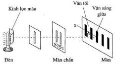
c. Interference pattern when using white light
If light sources S 1 and S 2 emit white light consisting of both
color light
has wavelength 0.4 0.76 m , then each chromatic light will give an interference pattern with its own color and different width i .
At the origin O , corresponding to x = 0, the maximum intersection condition is satisfied for all monochromatic light. At O, we obtain all monochromatic bright fringes in
wavelength range 0.4 0.76 m so the maximum fringe in the middle is a bright white fringe.
Because the width of the fringes depends on the wavelength, the larger the wavelength, the larger the distance between the two fringes. Therefore, on both sides of the central white bright fringe, the fringe systems of different monochromatic lights will be located at different positions. Corresponding to the same bright fringe level, the violet fringe is closest to the central fringe, and the red fringe is the farthest, forming a color band in violet, outside red .
1
2
3
Figure 2.12. Interference when using white light
At a certain position, we can obtain a superposition of many bright fringes of different colors corresponding to different fringe levels. The further away from the central bright fringe, the more bright fringes of different colors overlap, so the observed fringe color gradually blurs away from the central white bright fringe .
Problem 1:
Two Young slits are separated by a distance l = 1 mm , illuminated by light
monochromatic light with wavelength 0.6 m . The observation screen is placed at a distance from the plane
contains two slits of length D = 2 m .
a. Find the interference fringe spacing.
b. Determine the positions of the first three bright fringes (consider the central bright fringe as the zero-order bright fringe).
c. Determine the displacement of the interference fringes on the observation screen if in front of one of the two slits is placed a thin, parallel, transparent plate with a thickness of e = 2 m and refractive index n = 1.5 .
Prize:
a. Interference fringe interval:
i D
l
0, 6.10 6 .2 10 3
1, 2.10 3 m
b. The position of the bright fringe is determined by the formula:
y k D, k 0, 1, 2, 3...
s l
S
y D
1 liter
0, 6.10 6 .2 3
10 3 1, 2.10 m
y s 2
y s 3
2 D 2.4.10 3 ml
3 D 3.6.10 3 ml
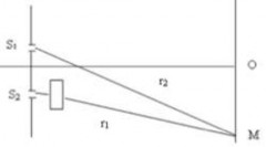
c. Displacement of the fringe system
When a transparent thin plate is placed in front of one of the two slits, the difference in the path length between the light rays from the two slits to a point on the screen changes. To know how the fringe pattern shifts, we must calculate the difference in the path length of the two light rays at a point on the screen.
From the figure we have the luminous flux:
L 1 L 2 ( r 1 e ) ne r 2 ( r 1 r 2) ( n 1) e
But:
therefore:
r 1 r 2
L L
y l D
y l ( n 1) e
1 2 D
The position of the bright fringe is determined by the condition:
L L y s l ( n 1) e k y k D( n 1) eD
1 2 D
ll
The dark position is determined by the condition:
L L y t l ( n 1) e (2 k 1) Dy (2k 1 ) D( n 1) eD
1 2 D
On the other hand:
2 liters
2 l l
y k D,
s l
y (2k 1 ) D
t l
The pattern shifts a distance:
y
e ( n 1) D l
2.10 6 .0,5.2 10 3
2.10 3 m .
2.3. INTERFERENCE CAUSED BY THIN PLATES
As we know, if we observe interference with a point light source, we will get very loose non-local interference fringes. However, in reality, point sources are difficult to implement, and in many cases, they cannot be implemented. Moreover, in nature, interference phenomena on thin plates are often observed with wide sources, such as interference phenomena on oil and grease films due to scattered light from a part of the sky. In this case, the experiment proves that the most loosely observed interference pattern is only in a very narrow region of space near the surface of the thin plate and when leaving that region, the fringes will quickly disappear. Therefore, people call this type of interference fringes local interference fringes.
When studying the transmission of light through thin plates, we see that part of the light is transmitted through the plate, and part is reflected back into the incident medium. The reflected and transmitted rays are separated from an incident ray, so they satisfy the combination condition. If they meet again, light interference will occur. To study this interference phenomenon, we first need to calculate the optical path of the light ray when reflected through the interference phenomenon due to reflection conducted by Lloyd.