CHAPTER 2 EXERCISES
Lesson 2.1.
Monochromatic light source ( 0.6 m ) shines on a flat screen E with two narrow slits
S 1 and S 2 are parallel and d=1mm apart and equidistant from the light source. Place flat screen M parallel and D= 103mm away from screen E. The distance between screens E and M is air ( n o =1 ). Maybe you are interested! Car body electrical practice - 8
zt2i3t4l5ee
zt2a3gs
zt2a3ge
zc2o3n4t5e6n7ts
If the voltage is out of specification, replace the wire or connector.
If the voltage is within specification, install the front fog light relay and follow step 5.
Step 5 Check the front fog light switch
- Remove the D4 connector of the fog light switch
- Use a multimeter to measure the resistance of the front fog light switch.
Measurement location
Condition
Standard
D4-3 (BFG) -D4-4 (LFG)
Light switchFront Fog OFF
>10kΩ
D4-3 (BFG) -D4-4 (LFG)
Front fog light switchON
<1 Ω
- Standard resistor
D4 connector is located on the combination switch assembly.
If the resistance is out of specification, replace the combination switch (the fog light switch is located in the combination switch).
If the resistance is within specification, follow step 6.
Step 6 Check wiring and connectors (front fog light relay-light selector switch)
- Disconnect connector D4 of the combination switch assembly
- Use a voltmeter to measure the voltage value of jack D4 on the wire side.
Measurement location
Control modecontrol
Standard
D4-3 (BFG) - (-) AQ
TAIL
11 to 14 V
D4 connector for the wiring of the combination switch assembly
If the voltage does not meet the standard, replace the wire or connector.
If the voltage is within standard, there may have been an error in the previous measurements.
Step 7 Check the front fog lights
- Remove the front fog light electrical connector.
- Supply battery voltage to the fog lamp terminals
Jack 8, B9 of front fog lamp on the electrical side
blind first.
Power supply location
Terms and Conditions
Battery positive terminal - Terminal 2Battery negative terminal - Terminal 1
Fog lightsbefore morning
- If the light does not come on, replace the bulb.
If the light is on, re-plug the jack and continue to step 8.
Step 8 Check wiring and connectors (relay and front fog lights)
- Disconnect the B8 and B9 connectors of the front fog lights.
- Use a voltmeter to measure voltage at the following locations:
Measurement location
Switch location
Terms and Conditions
B8-2 - (-) AQ
Electric lock ON TAIL size switchFog switch ON
11 to 14 V
B9-2 - (-) AQ
Electric lock ONTAIL size switch Fog switch ON
11 to 14 V
B8 and B9 connectors on the front fog lamp wiring side
Voltage is not up to standard, repair or replace the jack. If up to standard, there may have been an error in the measurement process.
2.2.4. Procedure for removing, installing and adjusting fog lights 1. Procedure for removing
- Remove the front inner ear pads
Use a screwdriver to remove the 3 screws and remove the front part of the front inner ear liner
-Remove the fog light assembly
+ Disconnect the connector.
+ Use a screwdriver to remove 3 screws to remove the fog light cover
2. Installation sequence
-Rotate the fog lamp bulb in the direction indicated by the arrow as shown in the figure and remove the fog lamp from the fog lamp assembly.
-Rotate the fog light bulb in the direction indicated by the arrow as shown in the figure and install the light into the fog light assembly.
- Use a screwdriver to install the fog light cover
-Install the electrical connector
Attention: Be careful not to damage the plastic thread on the lamp assembly.
- Install the front inner ear pads
Use a screwdriver to install the front inner bumper with 3 screws.
3. Prepare the vehicle to adjust the fog light convergence. Prepare the vehicle:
- Make sure there is no damage or deformation to the vehicle body around the fog lights.
- Add fuel to the fuel tank
- Add oil to standard level.
- Add engine coolant to standard level.
- Inflate the tire to standard pressure.
- Place spare tire, tools and jack in original design position
- Do not leave any load in the luggage compartment.
- Let a person weighing about 75 kg sit in the driver's seat.
4. Prepare to check the fog light convergence
a/ Prepare the vehicle status as follows:
- Place the car in a dark enough place to see the lines. The lines are the dividing line, below which the light from the fog lights can be seen but above which it cannot.
- Place the car perpendicular to the wall.
- Keep a distance of 7.62 m between the center of the fog lamp and the wall.
- Park the car on level ground.
- Press the car down a few times to stabilize the suspension.
Note: A distance of approximately 7.62 m is required between the vehicle (fog lamp center) and the wall to adjust the convergence correctly. If the distance of 7.62 m cannot be achieved, set the correct distance of 3 m to check and adjust the fog lamp convergence. (Since the target area varies with the distance, please follow the instructions as shown in the figure.)
b/ Prepare a piece of thick white paper about 2 m high and 4 m wide to use as a screen.
c/ Draw a vertical line through the center of the screen (line V).
d/ Set the screen as shown in the picture. Note:
- Keep the screen perpendicular to the ground.
- Align the V line on the screen with the center of the vehicle.
e/Draw the reference lines (H, V LH and V RH lines) on the screen as shown in the figure.HINT:
Mark the center of the fog lamp on the screen. If the center mark cannot be seen on the fog lamp, use the center of the fog lamp or the manufacturer's name mark on the fog lamp as the center mark.
H line (fog light height):
Draw a line across the screen so that it passes through the center mark. Line H should be at the same height as the center mark of the fog light bulb.
Line V LH, V RH (center mark position of left fog lamp LH and right fog lamp RH):
Draw two lines so that they intersect line H at the center marks.
5. Check the fog light convergence
a/ Cover the fog lamp or remove the connector of the other side fog lamp to prevent light from the unchecked fog lamp from affecting the fog lamp convergence test.
b/ Start the engine.
c/ Turn on the fog lights and make sure that the dividing line is outside the standard area as shown in the drawing.
6. Adjust the fog light convergence
Use a screwdriver to adjust the fog light to the standard area by turning the toe adjustment screw.
Note: If the screw is adjusted too far, loosen it and then tighten it again, so that the last rotation of the light adjustment screw is clockwise.
3. Self-study questions
1. Describe the operating principle of the lighting system with automatic headlight function
2. Describe the operating principle of the lighting system with the function of rotating headlights when turning
3. Draw diagram and connect lighting system on Hyundai Porter car
4. Draw diagram and connect lighting system on Honda Accord 1992
5. Draw the lighting circuit on a 1993 Toyota Lexus
LESSON 3 MAINTENANCE AND REPAIR OF SIGNAL SYSTEM
I. IMPLEMENTATION GOAL
After completing this lesson, students will be able to:
- Distinguish between types of signals on cars
- Correctly describe common symptoms and suspected areas causing damage.
- Connecting signal circuits ensures technical requirements
- Disassemble, install, check, maintain and repair the signal system to ensure technical requirements.
- Ensure safety in work and industrial hygiene
II. LESSON CONTENT
1. General description
The signal system equipped on cars aims to create signals to notify other vehicles participating in traffic about the vehicle's operating status such as: stopping, parking, braking, reversing, turning...
Signals are used either by light such as headlamps, brake lights, turn signals….. or by sound such as horns, reverse music….
Just like the lighting system. A signal system circuit usually consists of: battery, fuse, wire, relay, electrical load and control switch. Only some switches of the signal system are on the combination switch. The switches of other signals are usually located in different locations such as in the gearbox or brake pedal……
2. Maintenance and repair
2.1. Turn signals and hazard lights
The installation location of the turn signal is shown in Figure 3.1. The turn signal control switch is located in the combination switch under the steering wheel. Turning this switch to the right or left will make the turn signal turn right or left.
The hazard light switch is used when the vehicle has a problem while participating in traffic. When the hazard light switch is turned on, all the turn signals on the vehicle will light up at a certain frequency. The hazard light switch is usually placed separately from the turn signal switch (some old cars integrate the hazard and turn signal switches on the same combination switch cluster).
Figure 3.1 Turn signal switch Figure 3.2 Hazard switch
The part that generates the flashing frequency for the lights is called a turn signal relay. The turn signal relay usually has 3 terminals: B (positive power supply); E (negative power supply); L (providing the turn signal switch to distribute to the
lamp)
2.1.1. Circuit diagram
To generate the frequency for the turn signal, a turn signal relay is used in the turn signal circuit. The current from the turn signal relay will be sent to the turn signal switch assembly to distribute the current to the turn signal lights for the driver's purpose.
Figure 3.3. Schematic diagram of a turn signal circuit without a hazard switch
1. Battery; 2. Electric lock; 3. Turn signal relay; 4. Turn signal switch; 5. Turn signal lamp; 6. Turn signal lamp; 7. Hazard switch
Figure 3.4 Schematic diagram of turn signal circuit with hazard switch
1. Battery; 2. Combination switch cluster; 3. Turn signal;
4. Turn signal light; 5. Turn signal relay
Today's cars no longer use three-pin turn signal relays (B, L, E) but use eight-pin turn signal relays (figure 3.5) (pin number 8 is used for hazard lights).
For this type, the current supplying the turn signal lights is supplied directly from the turn signal relay to the lights.
div.maincontent .p { color: black; font-family:"Times New Roman", serif; font-style: normal; font-weight: normal; text-decoration: none; font-size: 14pt; margin:0pt; } div.maincontent p { color: black; font-family:"Times New Roman", serif; font-style: normal; font-weight: normal; text-decoration: none; font-size: 14pt; margin:0pt; } div.maincontent .s1 { color: black; font-family:"Times New Roman", serif; font-style: normal; font-weight: normal; text-decoration: none; font-size: 13pt; } div.maincontent .s2 { color: black; font-family:"Times New Roman", serif; font-style: italic; font-weight: normal; text-decoration: none; font-size: 14pt; } div.maincontent .s3 { color: black; font-family:"Times New Roman", serif; font-style: normal; font-weight: normal; text-decoration: none; font-size: 14pt; } div.maincontent .s4 { color: black; font-family:"Times New Roman", serif; font-style: normal; font-weight: normal; text-decoration: none; font-size: 13pt; } div.maincontent .s5 { color: black; font-family:"Times New Roman", serif; font-style: normal; font-weight: normal; text-decoration: none; font-size: 13pt; vertical-align: 1pt; } div.maincontent .s6 { color: black; font-family:"Times New Roman", serif; font-style: normal; font-weight: normal; text-decoration: none; font-size: 11pt; } div.maincontent .s7 { color: black; font-family:"Times New Roman", serif; font-style: normal; font-weight: normal; text-decoration: none; font-size: 14pt; vertical-align: -9pt; } div.maincontent .s8 { color: black; font-family:"Times New Roman", serif; font-style: normal; font-weight: normal; text-decoration: none; font-size: 11pt; } div.maincontent .s9 { color: #008000; font-family:"Times New Roman", serif; font-style: normal; font-weight: normal; text-decoration: none; font-size: 14pt; } div.maincontent .s10 { color: black; font-family:"Times New Roman", serif; font-style: italic; font-weight: normal; te
Car body electrical practice - 8
zt2i3t4l5ee
zt2a3gs
zt2a3ge
zc2o3n4t5e6n7ts
If the voltage is out of specification, replace the wire or connector.
If the voltage is within specification, install the front fog light relay and follow step 5.
Step 5 Check the front fog light switch
- Remove the D4 connector of the fog light switch
- Use a multimeter to measure the resistance of the front fog light switch.
Measurement location
Condition
Standard
D4-3 (BFG) -D4-4 (LFG)
Light switchFront Fog OFF
>10kΩ
D4-3 (BFG) -D4-4 (LFG)
Front fog light switchON
<1 Ω
- Standard resistor
D4 connector is located on the combination switch assembly.
If the resistance is out of specification, replace the combination switch (the fog light switch is located in the combination switch).
If the resistance is within specification, follow step 6.
Step 6 Check wiring and connectors (front fog light relay-light selector switch)
- Disconnect connector D4 of the combination switch assembly
- Use a voltmeter to measure the voltage value of jack D4 on the wire side.
Measurement location
Control modecontrol
Standard
D4-3 (BFG) - (-) AQ
TAIL
11 to 14 V
D4 connector for the wiring of the combination switch assembly
If the voltage does not meet the standard, replace the wire or connector.
If the voltage is within standard, there may have been an error in the previous measurements.
Step 7 Check the front fog lights
- Remove the front fog light electrical connector.
- Supply battery voltage to the fog lamp terminals
Jack 8, B9 of front fog lamp on the electrical side
blind first.
Power supply location
Terms and Conditions
Battery positive terminal - Terminal 2Battery negative terminal - Terminal 1
Fog lightsbefore morning
- If the light does not come on, replace the bulb.
If the light is on, re-plug the jack and continue to step 8.
Step 8 Check wiring and connectors (relay and front fog lights)
- Disconnect the B8 and B9 connectors of the front fog lights.
- Use a voltmeter to measure voltage at the following locations:
Measurement location
Switch location
Terms and Conditions
B8-2 - (-) AQ
Electric lock ON TAIL size switchFog switch ON
11 to 14 V
B9-2 - (-) AQ
Electric lock ONTAIL size switch Fog switch ON
11 to 14 V
B8 and B9 connectors on the front fog lamp wiring side
Voltage is not up to standard, repair or replace the jack. If up to standard, there may have been an error in the measurement process.
2.2.4. Procedure for removing, installing and adjusting fog lights 1. Procedure for removing
- Remove the front inner ear pads
Use a screwdriver to remove the 3 screws and remove the front part of the front inner ear liner
-Remove the fog light assembly
+ Disconnect the connector.
+ Use a screwdriver to remove 3 screws to remove the fog light cover
2. Installation sequence
-Rotate the fog lamp bulb in the direction indicated by the arrow as shown in the figure and remove the fog lamp from the fog lamp assembly.
-Rotate the fog light bulb in the direction indicated by the arrow as shown in the figure and install the light into the fog light assembly.
- Use a screwdriver to install the fog light cover
-Install the electrical connector
Attention: Be careful not to damage the plastic thread on the lamp assembly.
- Install the front inner ear pads
Use a screwdriver to install the front inner bumper with 3 screws.
3. Prepare the vehicle to adjust the fog light convergence. Prepare the vehicle:
- Make sure there is no damage or deformation to the vehicle body around the fog lights.
- Add fuel to the fuel tank
- Add oil to standard level.
- Add engine coolant to standard level.
- Inflate the tire to standard pressure.
- Place spare tire, tools and jack in original design position
- Do not leave any load in the luggage compartment.
- Let a person weighing about 75 kg sit in the driver's seat.
4. Prepare to check the fog light convergence
a/ Prepare the vehicle status as follows:
- Place the car in a dark enough place to see the lines. The lines are the dividing line, below which the light from the fog lights can be seen but above which it cannot.
- Place the car perpendicular to the wall.
- Keep a distance of 7.62 m between the center of the fog lamp and the wall.
- Park the car on level ground.
- Press the car down a few times to stabilize the suspension.
Note: A distance of approximately 7.62 m is required between the vehicle (fog lamp center) and the wall to adjust the convergence correctly. If the distance of 7.62 m cannot be achieved, set the correct distance of 3 m to check and adjust the fog lamp convergence. (Since the target area varies with the distance, please follow the instructions as shown in the figure.)
b/ Prepare a piece of thick white paper about 2 m high and 4 m wide to use as a screen.
c/ Draw a vertical line through the center of the screen (line V).
d/ Set the screen as shown in the picture. Note:
- Keep the screen perpendicular to the ground.
- Align the V line on the screen with the center of the vehicle.
e/Draw the reference lines (H, V LH and V RH lines) on the screen as shown in the figure.HINT:
Mark the center of the fog lamp on the screen. If the center mark cannot be seen on the fog lamp, use the center of the fog lamp or the manufacturer's name mark on the fog lamp as the center mark.
H line (fog light height):
Draw a line across the screen so that it passes through the center mark. Line H should be at the same height as the center mark of the fog light bulb.
Line V LH, V RH (center mark position of left fog lamp LH and right fog lamp RH):
Draw two lines so that they intersect line H at the center marks.
5. Check the fog light convergence
a/ Cover the fog lamp or remove the connector of the other side fog lamp to prevent light from the unchecked fog lamp from affecting the fog lamp convergence test.
b/ Start the engine.
c/ Turn on the fog lights and make sure that the dividing line is outside the standard area as shown in the drawing.
6. Adjust the fog light convergence
Use a screwdriver to adjust the fog light to the standard area by turning the toe adjustment screw.
Note: If the screw is adjusted too far, loosen it and then tighten it again, so that the last rotation of the light adjustment screw is clockwise.
3. Self-study questions
1. Describe the operating principle of the lighting system with automatic headlight function
2. Describe the operating principle of the lighting system with the function of rotating headlights when turning
3. Draw diagram and connect lighting system on Hyundai Porter car
4. Draw diagram and connect lighting system on Honda Accord 1992
5. Draw the lighting circuit on a 1993 Toyota Lexus
LESSON 3 MAINTENANCE AND REPAIR OF SIGNAL SYSTEM
I. IMPLEMENTATION GOAL
After completing this lesson, students will be able to:
- Distinguish between types of signals on cars
- Correctly describe common symptoms and suspected areas causing damage.
- Connecting signal circuits ensures technical requirements
- Disassemble, install, check, maintain and repair the signal system to ensure technical requirements.
- Ensure safety in work and industrial hygiene
II. LESSON CONTENT
1. General description
The signal system equipped on cars aims to create signals to notify other vehicles participating in traffic about the vehicle's operating status such as: stopping, parking, braking, reversing, turning...
Signals are used either by light such as headlamps, brake lights, turn signals….. or by sound such as horns, reverse music….
Just like the lighting system. A signal system circuit usually consists of: battery, fuse, wire, relay, electrical load and control switch. Only some switches of the signal system are on the combination switch. The switches of other signals are usually located in different locations such as in the gearbox or brake pedal……
2. Maintenance and repair
2.1. Turn signals and hazard lights
The installation location of the turn signal is shown in Figure 3.1. The turn signal control switch is located in the combination switch under the steering wheel. Turning this switch to the right or left will make the turn signal turn right or left.
The hazard light switch is used when the vehicle has a problem while participating in traffic. When the hazard light switch is turned on, all the turn signals on the vehicle will light up at a certain frequency. The hazard light switch is usually placed separately from the turn signal switch (some old cars integrate the hazard and turn signal switches on the same combination switch cluster).
Figure 3.1 Turn signal switch Figure 3.2 Hazard switch
The part that generates the flashing frequency for the lights is called a turn signal relay. The turn signal relay usually has 3 terminals: B (positive power supply); E (negative power supply); L (providing the turn signal switch to distribute to the
lamp)
2.1.1. Circuit diagram
To generate the frequency for the turn signal, a turn signal relay is used in the turn signal circuit. The current from the turn signal relay will be sent to the turn signal switch assembly to distribute the current to the turn signal lights for the driver's purpose.
Figure 3.3. Schematic diagram of a turn signal circuit without a hazard switch
1. Battery; 2. Electric lock; 3. Turn signal relay; 4. Turn signal switch; 5. Turn signal lamp; 6. Turn signal lamp; 7. Hazard switch
Figure 3.4 Schematic diagram of turn signal circuit with hazard switch
1. Battery; 2. Combination switch cluster; 3. Turn signal;
4. Turn signal light; 5. Turn signal relay
Today's cars no longer use three-pin turn signal relays (B, L, E) but use eight-pin turn signal relays (figure 3.5) (pin number 8 is used for hazard lights).
For this type, the current supplying the turn signal lights is supplied directly from the turn signal relay to the lights.
div.maincontent .p { color: black; font-family:"Times New Roman", serif; font-style: normal; font-weight: normal; text-decoration: none; font-size: 14pt; margin:0pt; } div.maincontent p { color: black; font-family:"Times New Roman", serif; font-style: normal; font-weight: normal; text-decoration: none; font-size: 14pt; margin:0pt; } div.maincontent .s1 { color: black; font-family:"Times New Roman", serif; font-style: normal; font-weight: normal; text-decoration: none; font-size: 13pt; } div.maincontent .s2 { color: black; font-family:"Times New Roman", serif; font-style: italic; font-weight: normal; text-decoration: none; font-size: 14pt; } div.maincontent .s3 { color: black; font-family:"Times New Roman", serif; font-style: normal; font-weight: normal; text-decoration: none; font-size: 14pt; } div.maincontent .s4 { color: black; font-family:"Times New Roman", serif; font-style: normal; font-weight: normal; text-decoration: none; font-size: 13pt; } div.maincontent .s5 { color: black; font-family:"Times New Roman", serif; font-style: normal; font-weight: normal; text-decoration: none; font-size: 13pt; vertical-align: 1pt; } div.maincontent .s6 { color: black; font-family:"Times New Roman", serif; font-style: normal; font-weight: normal; text-decoration: none; font-size: 11pt; } div.maincontent .s7 { color: black; font-family:"Times New Roman", serif; font-style: normal; font-weight: normal; text-decoration: none; font-size: 14pt; vertical-align: -9pt; } div.maincontent .s8 { color: black; font-family:"Times New Roman", serif; font-style: normal; font-weight: normal; text-decoration: none; font-size: 11pt; } div.maincontent .s9 { color: #008000; font-family:"Times New Roman", serif; font-style: normal; font-weight: normal; text-decoration: none; font-size: 14pt; } div.maincontent .s10 { color: black; font-family:"Times New Roman", serif; font-style: italic; font-weight: normal; te Working Principle Diagram Of Continuous Butter Making Equipment
 Factors Affecting the Principle of Business Prudence
 Machine part principle 2 - 1
 Simulating the shadowing of objects from a light source in virtual reality - 9
a. Calculate the width of the fringes on screen M and the position of the second bright fringe.
b. If a transparent liquid with refractive index n is filled in the space between screens E and M , the width of the fringes will be 0.45 mm . Calculate the refractive index n of the liquid.
Lesson 2.2.
Two Young slits are separated by a distance of l = 1mm , which is
shine by light
The wavelength of the light is λ = 0.5μm . The screen can be observed .
set away from the plane
two slits one segment
D = 2m .
a. Find the interference fringes .
b. Place a parallel, transparent, thin film with a thickness of e=12μm on the screen and observe it at a distance of 6mm from one of the two slits . Find the refractive index of the film .
Lesson 2.3.
A narrow monochromatic slit S 1 is above a flat mirror G (small in size), d=0.5mm from the mirror. Place a flat screen P perpendicular to the mirror surface, parallel to slit S 1 and D=3m from the slit . On screen P, bright and dark fringes are obtained, arranged alternately, and at point O is a dark fringe. The distance between 21 consecutive bright fringes is h=36mm .
a. Set up the formula to determine the position of bright and dark fringes on screen P.
b. Calculate the width of a fringe and the wavelength of the light source S1 .
Lesson 2.4.
Project a parallel, oblique monochromatic beam of light 60 0 from the surface
top of a glass wedge, placed in air. The refractive index of the wedge is n=1.5 . The angle of inclination of the wedge is very small. The wavelength of light is .
a. Write the formula to determine the position of the bright and dark fringes of the interference fringe system on the wedge surface according to the thickness of the wedge.
b. Simultaneously shine two parallel red and violet beams of light at an angle 60 0
relative to the wedge surface. Wavelength t
0.4 m , d
0.76 m , 2.10 4 rad . Find the surface
The smallest thickness of the wedge at which there is a red light streak and a purple light streak.
Lesson 2.5.
Between two flat glass plates ( n1 =1.5 ) placed at an angle to each othervery small, filled with transparent water ( n=4/3 ) , forming a water wedge. Shine a parallel monochromatic beam of light perpendicular to the bottom surface of the wedge. Observe on the top surface of the wedge alternating bright and dark fringes.
a. Establish the formula to determine the position of bright and dark fringes.
b. Simultaneously shine two parallel beams of red and violet light perpendicular to the bottom surface of the wedge. Calculate the distance between the second-order red fringe and the second-order violet fringe on the surface of the wedge. Knowing that the wavelengths of the red light and the violet light are respectively:
t 0.4 m , d
0.76 m , and 5.10 4 rad .
Lesson 2.6.
Parallel monochromatic light beam ( 0.6 m ) perpendicular to a thin plate ( n=1.5 ) placed in air. Observe that on the surface of the thin plate there are alternating bright and dark streaks.
a. Explain the phenomenon and establish a formula to determine the thickness of the thin plate corresponding to the light and dark streaks.
b. Find the smallest thickness of the plate where there are dark and light spots.
Lesson 2.7.
A parallel beam of monochromatic light with wavelength λ=0.5μm is perpendicular to one surface of an air wedge. Observing in the far light , the width of each interference fringe is measured as i=0.5mm .
a. Determine the angle of inclination of the wedge .
b. Simultaneously shine two chromatic light beams with wavelengths λ 1 = 0.5μm and λ 2 = 0.6μm onto the air wedge surface . Find the position where the dark fringes formed by the two light beams coincide. Consider the edge of the air wedge as a zero-order dark fringe.
Lesson 2.8.
A thin glass wedge has an angle of inclination α = 2' and a refractive index n = 1.52 . A parallel, achromatic beam of light is incident perpendicular to one side of the wedge . Determine the wavelength of the achromatic beam of light if the distance between two consecutive dark fringes is i = 0.3mm .
Lesson 2.9.
Two parallel monochromatic rays of light shine on the upper surface of a thin plate with a surface of
2
o
thickness d constant, refractive index n 1 with angle of incidence i 1 = 45 . Above the thin plate is
air ( n o =1 ), below is glass ( n 2 =1.5 ) thickness d=0.49µm , light wavelength 0.6 m .
a. Calculate the optical path of two rays meeting at M.
b. At M is the bright point or the dark point.
Lesson 2.10.
Shine a parallel monochromatic beam of light perpendicular to the flat glass plate of the device to produce Newton's circular interference fringes. Observe that the radii of two consecutive dark fringes are 4.38mm and 4.73mm respectively . The radius of the spherical cap R=6.4m . The refractive index of the glass of the device is n=1.5 .
a. Explain the formation of Newton's circular interference pattern. Give the order number of the two dark fringes mentioned above and calculate the wavelength of the light.
b. If transparent water ( n1 = 4 /3 ) is filled into the gap between the spherical cap and the flat glass plate of the instrument, how will the interference pattern change?
Lesson 2.11.
An apparatus for Newton's rings consists of a thin glass lens.
A flat-concave crystal ( n 2 = 1.5 ) with a concave surface radius of R = 2m is placed so that the concave surface faces up and is filled with transparent water ( n 1 = 4/3 ). A parallel monochromatic beam of light (wavelength ) is projected onto it. 0.65 m ) perpendicular to the water surface. Determine the thickness of the glass layer at the 10th dark fringe position and calculate the radius of that dark fringe.
Lesson 2.12.
The interference device for the Newtonian ring system consists of a flat horizontal glass cap (with the same refractive index n = 1.5 ). The radius of the cap is R = 8.6m . A parallel, monochromatic beam of light is shined perpendicular to the glass plate. The Newtonian ring interference pattern is observed, the diameter of the fourth dark fringe is 9mm . The center of the pattern is considered to be the zeroth dark fringe. The gap between the cap and the glass plate is air ( n o = 1 ).
a. Calculate the wavelength of light incident on the interference device.
b. If we pour liquid ( n1 =1.4 ) and fill the gap between the sphere and the glass plate , how will the interference pattern change?
Lesson 2.13.
Two flat glass plates ( n=1.5 ) are tilted to each other at a very small angle α, forming an air wedge between the slits. Shine a monochromatic beam of light
0.6 m perpendicular to the bottom surface of the air wedge. Observe the interference pattern on the wedge surface and on 1cm long of the wedge surface, there are 11 dark fringes.
a. Calculate the angle of inclination of the wedge.
b. If the above slit is filled with a transparent liquid with refractive index n1 =1.4 , how will the pattern change?
Lesson 2.14.
Shine a beam of white light onto a soap film (considered a thin plate with variable thickness, refractive index n=1.33 ). Find the smallest thickness of the soap film at which there are yellow reflected rays. Consider two cases:
a. The angle of incidence is 45 o .
b. The incident beam is perpendicular to the soap film.
Given the wavelength of yellow light
Lesson 2.15.
0.6 m .
Consider a system with Newton 's rings. Determine the thickness of the air layer where we observe the first bright fringe, knowing that the incident light has a wavelength of λ = 0.6μm .
Lesson 2.16.
Given a parallel chromatic light beam with wavelength λ = 0.6μm , perpendicular to the plane of a thin layer of air located between a flat glass plate placed in contact with the curved surface of a plano-convex lens . Find the thickness of the air layer at the position of the fourth dark fringe of the far beam . Consider the center of the Newton 's circular ring system as the number 0 fringe .
Lesson 2.17.
Given a parallel, chromatic beam of light shining perpendicularly on the plane of a thin air plate between a flat glass plate placed in contact with the curved surface of a plano-convex lens . The radius of the convex surface of the lens is R=15m .
Observe Newton's ring system through a far-field beam of light and measure the correct distance .
Between the fourth dark fringe and the second dark fringe, the distance between them is 9mm . Determine the wavelength of the chromatic light beam . Consider the center of the Newton 's circular pattern as the number 0 pattern .
Chapter 3.DIFRACTION OF LIGHT
3.1. LIGHT DIFFRATION PHENOMENON. HUYGENS-FRESNEL PRINCIPLE
3.1.1. Light diffraction phenomenon
In geometrical optics in a homogeneous medium, light travels in a straight line. However, experiments have shown that this is not always true. Consider the following two experiments:
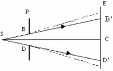
Experiment 1:Use a flashlight S to shine on a circular hole with diameter BD on a thick cardboard P (Figure 3.1). According to the law of rectilinear propagation of light, we can only observe light in the cone SB'D' created by the light rays passing through the edge of the circular hole. However, if we place our eyes
At point M outside and even quite far away this cone still receives light from S .
Figure 3.1
This proves that light propagates into the geometric shadow region, which means it does not obey the law of rectilinear propagation of light.
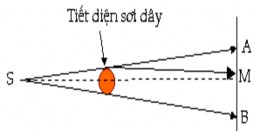
Experiment 2:Place a thick, circular piece of cardboard O parallel to a light slit. Behind the cardboard, place an observation screen E (Figure 3.2) parallel to O. According to the law of rectilinear propagation, the region AB is covered.
The region hidden by the string must be a geometric shadow region and the region outside must be uniformly illuminated. However, at point M on
Figure 3.2
The axis of symmetry of AB is in the geometric shadow region, we still see light.
and in the vicinity of points A and B we see dark and bright fringes.
This shows that in this case light also does not obey the law of rectilinear propagation.
In both experiments above, the perforated screen BD and the opaque cardboard O are the obstacles that play the role of redistributing the light intensity on the observation screen.
The phenomena observed in those two experiments are examples of light diffraction.
Definition
The phenomenon of light rays being deviated from rectilinear propagation when passing near objects
obstacle
small sized objects
call
is a present
how much
light radiation
Thank you now
how much
far from light
can be explained qualitatively
melon
on Huygens principle.
However, Huygens' principle
does not indicate how the light intensity on the screen placed behind the obstacle will be distributed. To solve this problem Fresnel
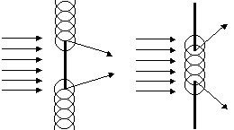
Figure 3.3
added the interference principle to Huygens' principle and established the Huygens-Fresnel principle. That is the basic principle of wave optics.
3.1.2. Huygens-Fresnel principle
a. Statement
Lip
point in space
light waves from real sources
send to
both become secondary light sources that emit light waves forward.
The amplitude and phase of the secondary source are the amplitude and phase given by the actual source.
cause ear
location of the source
According to the Huygens-Fresnel principle, when light shines on a circular hole, all points on the circular hole become secondary sources emitting secondary waves . The envelope of the secondary wavefronts is the wavefront. At the edge of the circular hole, the wavefront is bent and the wave rays
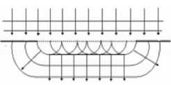
Figure 3.4. Qualitative explanation of light diffraction phenomenon
is always perpendicular to the wave front, so at the edge the wave rays are reversed relative to the direction of the incoming wave ( Figure 3.4 ) .
Each secondary light source on the circular hole BD has an amplitude and phase of oscillation exactly equal to the amplitude and phase of oscillation caused by light source S at that point. The light oscillation at each point on the screen E will be equal to the sum of the light oscillations caused by the secondary light sources on the circular hole BD at that point . From the expression
of the wave function, yes
thank you expression
By Huygens - Fresnel principle one can find
g of the light oscillation at a point M on the screen E ,
but the calculation is quite complicated because it requires integrals . Fresnel gave
an alternative method of calculation called the Fresnel sphere method which we
We will find out in the next section.
3.1.2.2. Wave expression Problem :
Let the light oscillation at source O have the form x a cos t , find the expression
Determine the light oscillation at M.

We apply the Huygens-Fresnel principle to write the expression for the light oscillation caused at M.
The point light source O can be replaced by a closed luminous surface S surrounding O. According to Huygens' principle, each point dS on surface S
both receive light sent by O so dS
are considered virtual sources broadcasting the secondary bridge.
Figure 3.5
level, they are coherent waves, so can interfere with each other.
Thus, to find the wave expression at M outside surface S, we do not need to pay attention to O but only need to use the secondary sources dS distributed on surface S.
According to Fresnel's principle, the light oscillation at dS sent by O has the form:
dx ( dS ) a ( dS ) cos ( t r 1 )
v
where a ( dS ) ~ a
r 1
is the amplitude of light oscillation caused by source O at dS .