Compressive strength (f' c ), MPa
Average shear stress (ν c ' ) , MPa
However, when the compressive strength of concrete is above 90MPa, the shear strength increases insignificantly. The graph shows that it would be incorrect to extrapolate according to current standards for concrete with compressive strength up to 100MPa.
Figure 2.14. Comparison of experimental and standard shear strength when increasing compressive strength to 100MPa [102]
d. Effect of steel fiber content
As the fiber content increases, the crack width decreases. In addition, the fiber content has a great influence on the shear strength because it improves the ductility and tensile strength of concrete [48]. With only a small amount of steel fiber content (0.75%), the shear strength of the beam increases significantly. Many studies have shown that as the fiber content increases, the shear strength of fiber-reinforced concrete increases, thereby significantly increasing the shear strength [48], [71], [92], [107]. When the fiber content increases from 0.8% to 1.6%, the shear strength increases from 275% to 485% [115]. When the fiber content increases, the shear strength increases significantly, however, the fiber content should only be taken less than 2% because according to the research of authors such as Guray Arslan, Riza Secer Orkun Keskin, Semih Ulusoy [66], the fiber content up to 3%, the shear strength does not increase with a/d ratio less than 3.5. When a/d is greater than 4.5, the beam failure model is due to bending instead of shear.
The steel fiber content is related to the post-cracking tensile stress as shown in formula (2-2). The post-cracking tensile stress is also related to the contribution of the concrete in the tensile zone of the reinforced concrete beam.
pc f D
f
AV AF(2-2) | |
In which: A is the coefficient analyzed by regression from experimental data. β - is the coefficient indicating the ability of diagonally cracked concrete to transmit tensile and shear forces τ- Adhesion force between steel fibers and concrete V f - Steel fiber content L f - Length of steel fiber D f - Fiber diameter | |
Maybe you are interested!
-

 Developing students' learning ability in teaching History at experimental high schools through grade 10 standard program - 18
 -
 Standard Teaching Hour Norms of Lecturers at Khxhnv University - Hanoi National University According to Each Position
 -
 Absolute growth rate of experimental chickens over weeks of age
 -
 Comparison of Geographical Conditions, Structure of Culture and Tourism Activities
 -
 Comparison of Distribution by Number of Cesarean Sections Between Studies
![Comparison of Experimental and Standard Shear Strengths When Increasing Compressive Strength to 100Mpa [102]](https://tailieuthamkhao.com/en/uploads/2025/03/28/comparison-of-experimental-and-standard-shear-strengths-when-increasing-compressive-strength-to-445x306.jpg)
e. Effect of longitudinal reinforcement content (ρ).
The influence of longitudinal reinforcement content on the shear capacity of beams is clearly shown in the formulas for calculating the average shear stress. In standards such as ACI 318-05 [35], RILEM TC162-TDF [104], the influence of longitudinal reinforcement content is also clearly shown through the formula for calculating the shear resistance on the inclined section. In the formula for calculating the shear stress of studies such as Narayanan and Darwish [95]; Mansur, Ong, and Paramasivam [87]; Hai H. Dinh; Gustavo J. Parra-Montesinos [71], M.ASCE; and James K. Wight [71], the parameter is longitudinal reinforcement content. The longitudinal reinforcement content affects the shear resistance through the pin effect.
f. Influence of fiber shape and size
The primary role of steel fibers is to bridge cracks caused by tensile stress. Depending on the adhesion, the steel fibers may break or pull away from the concrete as the crack widens. The development of different types of fibers stems from the desire to improve the adhesion between the steel fibers and concrete.
Regarding the shape of the fibers, many authors believe that the bent or wavy fibers have better load-bearing capacity than straight fibers. When the fibers are bent, they have good adhesion to the concrete, making them less likely to be pulled off. According to Hai H.Dinh [70], the larger the surface area of the fiber in contact with the concrete, the greater the adhesion force. Square-section fibers adhere better than round-section fibers, when they have the same length. Fiber shapes in general tend to have non-straight shapes, such as bent at both ends, wavy, and extended fiber ends, which have been used.
When subjected to tension, the open-end, hooked-end fibers typically bend significantly and yield before breaking. This process allows the hooked-end fiber reinforced concrete to absorb a large amount of energy before failure.
Mohammad S. Islam and Shahria Alam [92] confirmed that with wavy and double-crown yarns, the shear resistance increases. The shape and length of the yarn are related to the yarn factor F as shown in formula (2-3).
L f f D
f
FV(2-3) |

Models for predicting shear strength of CST concrete beams
2.2.1. Models in current standards
In the world, there have been many design standards that provide models for calculating the shear strength of reinforced concrete beams. Some standards have proposed calculating the shear strength of beams based on experimental models, while others are based on theoretical models combined with experiments. Models in standards such as: ACI 544-4R88 [32], RILEM TC 162 [104], fib MODEL CODE 2010, EHE-08 [57], DIN-1045-1 [54],
MC2010… proposed a formula for predicting the shear strength of steel fiber reinforced concrete beams with or without stirrups.
RILEM TC 162 TDF standard
RILEM TC 162 TDF standard [104] proposed the formula for calculating the shear strength of steel fiber reinforced concrete beams using stirrups as follows:
CD WDS FDS V = V+ V+V(2-4) |
In which: V cd - Shear strength of concrete in compression zone; V wd - Shear strength of stirrup and diagonal reinforcement; V fd - Shear strength of steel fiber reinforcement.
V 0.12 k 100 f 1 /3 0.15 bd
(N)
With:
cd 1 1 f ck cp w
k 1 : Size coefficient; ρ 1 : Longitudinal reinforcement content;
200
d
k 1 1 (mm)
1 As / b w d 2 %
f fck : Is the tensile strength of concrete when cracked V fd =0.7k f k 1 τ fd b w d
With: k f : Influence coefficient of the participation of the wing section in the T-section; k f = 1+ n (h f /b w ) (h f /d) and k f < 1.5
h f : Height of beam flange (mm); b f : Width of flange (mm);
b w : Width of beam rib (mm);
n= (b f -b w )/h f when n≤3 and n≤3b w /h f
τ fd : Adhesion force between steel fiber and concrete, MPa
V w d
A s w 0.9 df s
ywd
(1 cot ) sin
With: s is the distance between the belts, mm
α is the angle created by the stirrup, diagonal reinforcement and the longitudinal axis of the beam, degree
ACI 544-4R88 standard
According to ACI 544-4R 88 [32] standard, the shear strength of reinforced concrete beams includes: shear strength of concrete, shear strength of stirrups, shear strength of steel fiber reinforcement and longitudinal reinforcement. The ultimate shear strength, V rd , for steel fiber reinforced concrete flexural members with stirrups is calculated by the sum of the resistance due to concrete V rd,c ; due to stirrups in the beam rib, V rd,w , and due to the contribution of steel fiber reinforcement, V rd,F :
Vrd = Vrd,c ++Vrd,s + Vrd,F(2-5) |
V rd,F is the shear strength of the reinforced concrete, calculated according to the formula:
(2-6) | |
With: ( k ) f ( d ) 1/ 4 cr ct a |
f ct : Indirect tensile strength of BTCST (tested by splitting compression method)
k: Conversion factor from indirect tensile strength to direct tensile strength. d: Effective height of the section
b w : effective width of the cross section.
Standard EHE-08, Appendix 14:
According to appendix 14 of Spanish EHE-08 standard [57], the design shear strength of reinforced concrete beams is calculated as formula (2-7)
u2 cu fu su V= V+V+ V(2-7) |
In which: V cu is the design shear strength due to the contribution of concrete;
V su is the design shear resistance due to the contribution of stirrups. These two values are calculated as in a reinforced concrete beam without fiber reinforcement.
V fu is the design shear strength due to the contribution of the fiber reinforcement, calculated the same as in the RILEM standard. The only difference is the value of stress increase due to the steel fiber reinforcement ( τ fd ), applied in the standard as formula (2-8)
fd ctR,d τ=0.5f(2-8) |
The contribution of the fiber is as follows:
(2-9) |
In which: f ctR,d = 0.33· f R3,d ;
f R3,d is the residual bending tensile strength corresponding to the crack opening - Crack Mouth Opening Displacement (COMD) of 2.5mm.
(200 / d )
ξ: Is the size coefficient, 1 2
d: Effective height of the beam; b o : Effective width of the beam.
Standard fib Model Code 2010 [46]
According to this standard, the shear strength of a steel fiber reinforced concrete beam with stirrups includes two components: Shear strength due to the contribution of stirrups and shear strength due to the contribution of steel fiber reinforced concrete.
Vu = V us + V R (2-10)
In which: V us is the shear strength due to the contribution of the stirrup;
VR is the shear strength due to the contribution of concrete and steel fiber reinforcement.
V kbd e (100 f (1 7.5 f Ftu )) 1/3
(2-11)
R 1 cm
c ct
In there:
γ c is the safety factor of concrete, f cm - concrete grade (cubic specimen compressive strength); f Ftu Ultimate residual tensile strength of reinforced concrete, corresponding to the ultimate crack width w u =1.5mm.
To calculate according to the model in this standard, experimental data of values of c f cm and f Ftu are needed for each type of concrete with different fiber content and different concrete grades. The experiments are quite complicated and difficult to perform, especially when the equipment is not popular.
2.2.2. Experimental models
Since the late 20th century, many scientists have studied the shear behavior of steel fiber reinforced concrete beams and proposed experimental models to calculate the shear strength of steel fiber reinforced concrete beams [41], [94], [95], [99]. Experimental models often consider the contribution of steel fibers to the shear strength of beams separately. Experimental models have predicted the shear strength of steel fiber reinforced concrete beams in an approximate and simple way. Due to the limited number of research samples, it is difficult and expensive to fully consider all aspects of shear behavior. Experimental models often cannot comprehensively evaluate the factors affecting shear strength and often have to ignore some factors to reduce the number of test samples.
The experimental model of the authors Sharma [106] has proposed a formula for calculating the shear strength of the reinforced concrete beam as (2-12). The formula proposed by Sharma shows that the calculated shear force depends on the splitting compressive strength (f ct ) of the reinforced concrete cylinder , and also shows that the ratio a/d also affects the shear strength. However, this calculation formula only calculates for normal strength reinforced concrete without stirrups (2-12).
k f d 1/ 4cr ct a
() ( )(2-12) |
In which: k=2/3, it can be understood that kf ct is the direct tensile strength. Shamma relied on the experimental study of Wright (1955), according to Wright , the direct tensile strength will be equal to 2/3 of the indirect tensile strength ( f ct ); a is the distance from the point of concentrated force to the beam support; d is the effective height of the beam.
In 1986, Mansur, Ong, and Paramasivam [87] proposed a model for calculating shear strength as shown in Figure 2.15. Based on experimental research, the authors developed a formula for calculating shear strength of fiber-reinforced concrete beams without stirrups with compressive strength of concrete up to 100MPa.
0.9d
Figure 2.15 Calculation model of cutting reinforced concrete beams without stirrups [81]


First, the authors considered the formula for calculating the shear strength of conventional concrete beams without steel fiber reinforcement in ACI-ASCE Committee 426 (1973) and added the contribution of steel fiber reinforcement through the post-cracking tensile strength (σ pc ) of the reinforced concrete beam determined by direct tensile testing as in equation (2-13).
Example LV 0.167 f ' 1.72 V f bd 0.29 f ' bd bd
c cw M f D wcw pc w
f
(2-13) |
In equation (2-13) the critical index M/V is taken as follows:
M M max a
; With a/d <=2
VV 2
M M max d
; With a/d >2
VV
In there:
M: Calculated moment at the considered cross section. Nmm V : Calculated shear force at the considered cross section, N
b w : Effective width of beam section, mm d : Effective height of beam, mm
f c : Compressive strength of concrete, MPa
ρ w : Main longitudinal reinforcement content within the beam rib τ: Adhesion force between steel fiber and cement mortar
Equation (2-13) accurately predicted the shear strength of the beams. The direct tensile test also gave the most basic tensile strength of fiber reinforced concrete. The disadvantage of this test is that it is difficult to perform because the research on the post-cracking tensile strength of CST concrete is still incomplete.
The experimental model of Narayanan and Darwish [95] has proposed a formula to calculate the “ultimate shear stress” of the inclined section. According to this calculation model, the cylindrical specimen split compressive strength ( f ct ) and the post-cracking tensile strength of fiber reinforced concrete have been used to calculate the ultimate shear stress. In this calculation model, the fiber shape has also been considered through the coefficient F (the influence factor of fiber distribution and fiber shape as well as fiber content), the pin effect (as a function of the longitudinal reinforcement content ρ), the ratio of the shear span to the effective height (a/d) and the longitudinal fiber tensile force along the inclined crack expressed as a function of v b . However, it is only calculated for concrete with normal strength.
e A f e B d u ct a b
.' .'(2-14) |
In which: e is the coefficient considering the arch effect in the shear behavior of the beam. The coefficient e is approximately equal to 1 when the beam is thin (a/d > 2.8) and equal to 2.8d/a when the beam is short (a/d <=2.8). ρ is the longitudinal reinforcement content. Based on the analysis of the compression zone on the inclined section, the following formula is proposed to calculate the split compressive strength related to the cube compressive strength ( f cuf ) as follows:
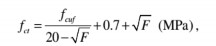
In which: F is the fiber coefficient,
L
f
F V f D
The adhesion coefficient β, suggested by the
f
The formula of Narayanan and Kareem-Palanjian (1984) is taken as 0.5; 0.75; 1 for round fibers, hooked fibers and edge-cut fibers, respectively. A' and B' are determined based on regression analysis of 91 test specimens and proposed: A'=0.24 and B'=80MPa; ν b is the contribution of steel fiber reinforcement due to tensile stress in the fiber reinforcement along the 45 0 inclined crack . ; ν b depends on the adhesion stress between the fiber and the matrix phase (τ) and the geometric ratio of the fiber as in equation (2-15)