generators, power transformers and auxiliary equipment in the factory, in the machine room often use bridge cranes. In addition to the main machine room, often use gate cranes or other types of cranes such as winches, hydraulic jacks... placed on site. The water intake and discharge pipes are also equipped with trash screens, valve gates and other hydromechanical equipment. The transformer station is placed in parallel upstream or downstream of the generator units to shorten the length of the generator busbars. In the condition that the factory is across the dam with a long discharge pipe, placing the transformer station downstream of the factory is very convenient and economical.
XVI. 1. 2. Classification of hydroelectric plants
Hydroelectric plants are classified in the following ways:
1. Classification by installed capacity
This classification is relative because it depends on the level of economic and technical development of each country and each country also depends on each period. In general, factories are usually classified relatively into the following types:
Maybe you are interested!
-

 Classification Table of Overdue Debt Ratio by Collateral of Seabank
 -
 Classification of the Convenience of 3 Types of Tourism
 -
 Classification of Wood Processing Enterprises by Economic Sector
 -
 Classification of Industrial Enterprises, Industrial Enterprises of Industrial Activities
 -
 Water Supply Methods and Valve Components on Turbine Pipes
Small hydroelectric power station, when: installed capacity N lm < 5,000 kW;
Average hydroelectric station, when:
N lm = 5,000 - 50,000 kW;
Large hydroelectric station, when:
N lm
> 50,000 - 1,000,000 kW.
According to TCVN 285 - 2002, the following levels of TTĐ are divided:
Level V hydroelectric station, when:
N lm
< 200 kW;
Level IV hydroelectric station, when:
N lm
< 5,000 - 200 kW;
Level III hydroelectric station, when:
N lm
< 50,000 - 5,000 kW;
Level II hydroelectric station, when:
N lm
< 300,000 - 50,000kW;
Level I hydroelectric station, when:
N lm
300,000 kW;
When the TTĐ has N lm
> 1,000,000 kW is usually considered a special class TTD.
2. Classification according to upstream water pressure plant conditions
Classified this way we have:
Hydroelectric power plant across the dam (the plant directly bears the upstream water pressure); Hydroelectric power plant behind the dam and the transmission line plant (not directly bears the upstream water pressure).
3. Classification by water column of Hydroelectric station
Classified this way we have:
Low water head hydroelectric station, when:
H max < 50 m;
Hydroelectric station with average water column, when: 50 m H max
400 m;
High water column hydroelectric station, when:
H max
> 400 m.
For water columns below 500 m, low-speed shaft turbines or bucket turbines can often be used. For water columns above 500 m, bucket turbines can be used.
4. Classification by factory structure
According to this classification, we have the following types of factories:
Hydroelectric power plant without flood discharge (flood discharge works located outside the plant); Hydroelectric power plant with flood discharge (flood discharge works located inside the plant);
Structurally combined hydroelectric power plants (plants in the dam body, plants in the piers, plants in the water discharge tower ....);
Underground and semi-underground plants; Pumped storage hydroelectric plants; Tidal hydroelectric plants ...
XVI. 2. CHARACTERISTICS AND STRUCTURE OF TYPES OF POWER PLANTS
In the Hydropower section we have learned that there are basic types of power stations and within them there are special types of stations, they follow general requirements but each type will also have its own special features.
1. Horizontal dam hydroelectric plant
The horizontal dam hydroelectric plant (Figure 16-2) is a part of the dam, so it is directly subject to the upstream water pressure, and is also a structure that takes water directly into the turbine. Therefore, this type of plant is often used with small water heads (H 30 - 40 m). Large and medium-sized plants often use vertical shaft turbines. Large units have a turbine diameter D 1 = (10 - 10.5) m (For example, Xaratop Hydroelectric Plant, in
Former Soviet Union has D 1 = 10.3m), N TB = (120 - 150) MW, Q TB = (650 - 700) m 3 /s. Lower part
The water of this type of plant is in a more unfavorable working condition than the ones after the dam and the conduit. The water pressure from one side requires the plant to be stable and not slide along the base, and when built on a non-rock foundation, the stability of the foundation and anti-settlement must also be considered, as a water barrier. Because of the need to ensure solidity and stability, as well as the large size and complex shape of the turbine chamber and the discharge pipe, the underwater part of the horizontal dam hydroelectric plant, the type located right on the construction line, is often the most expensive part of the project. The water intake is located right in front of the turbine chamber, with grooves for releasing trash screens, repair valve grooves, and working valve grooves. Use a mobile crane above to lift and lower the screens and valves. In case of large, dangerous floating objects, an additional breast wall 10 can be installed to block (Figure 16-2); groove 5 is arranged to release the working valve when it is necessary to prevent water from entering the spiral chamber. If there is a combined flood discharge in the plant, a repair valve groove 9 of the spillway with pressure 3 is installed; At the end of the discharge line, the spillway valve 4 is placed. The arrangement of the flood discharge structure in the factory will increase the water column of the station during the flood season and reduce the width of the spillway, leading to a reduction in the volume of the station structure. Above the diffusion section of the long discharge pipe, the auxiliary equipment is arranged, the power distribution room supplies the generator voltage, above it is the transformer station... To operate the downstream valve, the above picture also uses a gantry crane. Highway 6 and railway line 7 are also placed above the outlet of the discharge pipe. The high-voltage distribution station is located above the discharge pipe and above the factory.
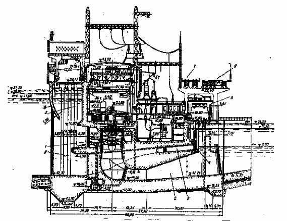
Figure 16-2. Horizontal dam hydroelectric plant with flood discharge.
2. Hydroelectric Plant after the dam:
The post-dam hydroelectric power plant is often used for stations with dry dams and spillways with medium and high water heads. For the post-dam plant, a circular metal vortex chamber is often used. Thanks to the structural changes of the plant, the underwater part is greatly reduced. The upper part can use other structures or the same as in the dam-crossing plant. Figure (16-3) shows a type of plant with a completely independent structure, located behind the dam without spillways. In this type of plant, the discharge pipe is not long enough to place the transformer, so it is appropriate to use the space between the dam and the plant to place the transformer station.
High voltage power poles can be placed on the concrete dam body. Hydroelectric power plants behind the dam are often used with water heads from (30 - 45) m H (250 - 300) m. Turbines used are usually axial turbines, high head rotary turbines or cross-oriented turbines. To reduce the effect of uneven settlement, a settlement joint is placed between the concrete dam and the plant.
Figure (16-4,a) is an example of a post-dam hydropower plant, the plant is located behind a concrete spillway. In this case, the electrical equipment is difficult to arrange, and the distribution room and the transformer station are usually arranged between the machine room and the dam. Figure (16-4,b) shows a dam-type hydropower plant with the plant located in a dry concrete dam body. Placing the machine room in the dam body will shorten the length of the penstock, thereby reducing the loss of water column.
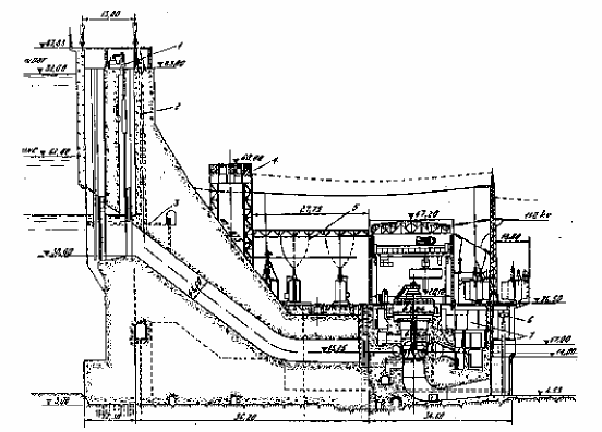
Figure 16-3. Hydroelectric plant after dam
Improve the operating conditions of the generator set working in a stable humidity and temperature environment, reduce the amount of concrete. However, ventilation, lighting, and moisture-proof conditions must be paid attention to. Communication with the outside and placing the transformer inside is cramped, a tunnel must be arranged to communicate outside and place the transformer outside downstream of the plant.
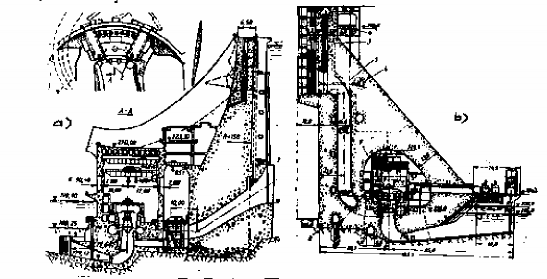
Figure 16-4. Hydroelectric power plant behind the spillway and inside the dam body.
3. Conduit type hydroelectric plant:
The run-off type hydropower plant is basically the same as the post-dam hydropower plant, but the only difference is that the underwater part of the plant is smaller due to the small diameter of the turbine, especially when installing a bucket turbine. At high head run-off stations, using a centrifugal turbine, in some cases, a straight cone-shaped discharge pipe or a trumpet discharge pipe is used, so the structure of the lower part is also simpler, and the water after leaving the discharge pipe flows to the downstream discharge channel. Figure (16-5) describes the structure of the station area of an open-air run-off power plant.
Figure 16-5. Conduit hydroelectric plant.
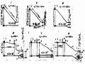
1- anchorage steel of anchorage; 2- upper open anchorage; 3- temperature joint; 4- support abutment; 5- lower anchorage; 6- steel sheet pile; 7- pressure wall of BAL
This diagram includes the pressure wall 7 of the pressure tank, connecting from the pressure tank to the factory is a steel pressure pipe with a belt, the factory uses a low-head water column turbine. The upper anchor 2 of the pipe is combined in the pressure wall component of the pressure tank, the anchor is open type. The lower anchor 5 is a component of the underwater part of the factory, using a closed type anchor. The temperature joint 3 is placed right after the upper anchor. Here, a separate water supply method is used, the pipe length is short. The transformer station and the high-voltage distribution station are located in a separate area, one end of the factory. In general, the pipeline-type factory has a structure that is not special compared to the hydroelectric plant after the dam.
4. Underground hydroelectric plant:
The difference between underground factories and other types of factories is that the entire factory is located underground in the rock, connecting the factory to the outside by tunnels and private wells. Depending on the hardness of the geology surrounding the factory, the structure is different: if the factory is located in a solid rock block, there is no need for a bearing layer, if the rock block is weak, there must be a bearing layer surrounding it (Figure 16-6).
To protect the machine room from water seepage and condensation appearing on the stone surface or the layer on the concrete coat, the arch wall ... usually builds a coat, between the coat and the stone layer is no
air. Use ventilation equipment to blow through the space to remove moisture. In low and medium head hydroelectric stations, the turbine size is large, and the plant is located in weak and cracked rock, so the plant only has turbines, generators and bridge cranes.
Figure 16-6. Ground plan of underground hydroelectric plant.
1- Mechanical workshop. 2- Oil tank. 3- Assembly floor. 4- Ventilation well. 5- Rail for transporting pipe sections. 6- Self-closing door. 7- Self-use transformer. 8- TT control room. 9- Circuit breaker. 10- Tuy
cable guide; 11- MBA tunnel. 12-Reserve MBA. I- First MBA group. II- Second MBA group.
The emergency valve at the end of the pipeline and the exhaust pipe repair can be arranged in a separate tunnel along the factory. When the factory is not located deep from the ground, the transformer can be placed on the ground. The tunnel is used to conduct the power line from the generator to the transformer. The transformer repair can be carried out at the high-voltage distribution station, or the tunnel can be used to bring the transformer to the assembly floor in the factory for repair.
For plants located quite deep underground, the transformer is arranged in a separate tunnel running parallel to the plant (see Figure 16-6).
For factories with high water heads using large-speed centrifugal turbines, due to the reduced size of the machine unit, the transformer can be placed directly near the machine room in the same compartment and has a separate wall for protection. This reduces the power loss from the generator busbar to the transformer, simplifies the wiring diagram and the working conditions of the rock mass around the factory are stable because the number of tunnels dug in the rock is small.
To ensure suitable temperature and humidity for operating personnel and normal working conditions of equipment, underground factories need to have air conditioning, ventilation and dust extraction systems, and can use heat from generators and transformers to heat the machine room in cold weather.
5. Pumped storage hydropower plant:
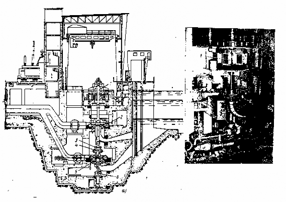
Figure 16-7. Pumped storage hydroelectric plant with "three-machine unit".
1- engine - generator; 2- shaft turbine; 3- clutch; 4- synchronous bucket turbine; 5- multi-stage pump; 6- support base.
The structure of a pumped-storage power plant is generally similar to other plants, only the underwater part is different. To ensure the working cycle, both a turbine and a generator are placed in the plant. In all cases, the working water column of the turbine is slightly smaller than the water column created by the pump. It is possible to use centrifugal turbines, rotary blades, and cross-blade turbines as pumps. To do that, it is necessary to change the direction of rotation, and the generator is converted into an electric motor. Such units are reversible units, allowing to simplify the plant layout, reduce the size and construction cost. When the water column H = (12÷15) m, the horizontal shaft reversible cable turbine is the most efficient. Using a unit with a reversible turbine and a generator - motor is called a " two-machine unit ".
When the water column is higher than 100 - 150 m, the " three-machine set " consisting of turbine, pump, generator - motor is widely used (see figure 16-7). The pump is placed deeper than the turbine. Between the connecting shaft of the turbine and the pump shaft, a clutch is used to disconnect the turbine or pump when operating in the corresponding mode. Under the clutch, an auxiliary synchronous bucket turbine is arranged.
used when putting the pump unit into operation without having to temporarily stop the engine. This diagram allows to improve the efficiency of the unit. To reduce the axial force acting on the bearing of the generator - engine, a support base is arranged under the pump to support the weight of the pump.
In addition to the above types of factories, in reality, hydroelectric construction also has many other types of factories (such as open-air factories, semi-underground factories, factories in pillars, ...) which are very diverse.
XVI. 3. EQUIPMENT IN HYDROELECTRIC PLANT
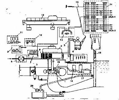
Figure 16-8. Technological diagram of hydroelectric equipment arrangement
1-turbine; 2- generator; 3- turbine front valve; 4- transformer; 5- power cable; 6- generator cooling device;
7- Measuring and control system; 8- Technical water supply system; 9- Compressed air system; 10- Excitation system; 11- Oil system; 12- Crane; 13- TT control room; 14- Distribution station; 15- Transmission line of the station; 16- Discharge valve; 17- Pressure oil tank; 18- Speed control cabinet; 19- DCTL; 20- Drainage system.
The equipment of a hydroelectric station can be divided into the following types: dynamic equipment (including turbines and generators), mechanical equipment, auxiliary equipment, and electrical equipment. To understand the general relationship between them, you can see the general diagram (Figure 16-8) on the above page. The following will review the related equipment learned in the subjects and supplement it if necessary. As for the hydraulic turbine and the mechanical-hydraulic auxiliary equipment systems mentioned in Part I of this textbook, they will not be presented again.
XVI. 3. 1. Generator of TTD
Generator is a device that converts the mechanical energy of the turbine into electrical energy to supply the electrical system. It is a three-phase synchronous generator with low rotation speed and salient poles. The main parts of the generator are: rotor rotating part, stator static part, excitation system, generator cooling system, fire protection system, water compression...
The working principle of the generator has been presented in the subject of Electrical Engineering, the generator can be mounted on a horizontal axis, vertical axis, or oblique axis. In this section, we only present the vertical axis generator, which is often found in the construction of medium and large hydropower plants.